九州大学学術情報リポジトリ
Kyushu University Institutional Repository
住宅の分散型エネルギー機器組み合わせにおける設 備容量の最適化
高, 翔翔
https://doi.org/10.15017/1398304
出版情報:Kyushu University, 2013, 博士(工学), 課程博士 バージョン:
権利関係:Fulltext available.
submitted to Kyushu University
in fulfillment of the requirements for the degree of
Department of Architecture in
Graduate School of Human-Environment Studies
by
大学院人間環境学府 Graduate School of Human-Environment Studies
My beloved parents,
Only parents, but you give your all.
Your love & emotional support of my education Have been a constant
For as long as I can remember.
Only parents, but the best of all.
Abstract... V Acknowledgements ... VII Publications Arising ... XI Nomenclature ... XIII I. Nomenclature for Chapter 2 ... XIII II. Nomenclature for Chapters 3-5 ...XVI List of Figures ... XXI List of Tables ... XXV
1. Introduction ...1
1.1 Background ... 2
1.2 Objectives ... 4
1.3 Organization ... 5
2. Chinese Kang ...7
2.1 Background ... 8
2.2 Outline of thermal process ... 9
2.2.1 Outdoor interferences ...11
2.2.2 Heat transfer of kang ...11
2.2.3 Indoor interferences ...12
2.2.4 Ventilation ...13
2.3 Mathematical modeling ...13
2.3.1 Kang-heating room ...13
II Contents
2.3.2 Chinese kang... 19
2.3.3 Programs of modeling ... 22
2.4 Field measurement ... 23
2.4.1 Conditions and scheme ... 23
2.4.2 Results and discussions ... 25
2.5 Model verifying ... 28
Conclusion ... 32
3. Modeling of DER Devices ... 33
3.1 Photovoltaic device ... 34
3.1.1 Mathematical modeling ... 34
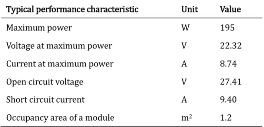
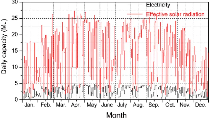
3.1.2 Generation capacity & efficiency analysis ... 40
3.2 Solar water heating device ... 41
3.2.1 Mathematical modeling ... 42
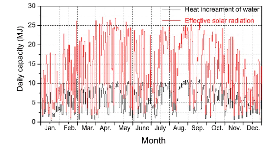
3.2.2 Generation capacity & efficiency analysis ... 47
3.3 Fuel cell device... 49
3.3.1 Mathematical modeling ... 50
3.3.2 Generation capacity & efficiency analysis ... 53
Conclusion ... 55
4. Integration of DER devices ... 57
4.1 Data collection and calculation ... 58
4.1.1 Introduction of objective building... 58
4.1.2 Data collection ... 59
4.1.3 Electric power load calculation ... 60
4.1.4 Hot water thermal load calculation ... 61
4.2 Operation strategy design ... 62
4.2.1 Electric power operation modes... 62
4.2.2 How water operation modes ... 63
4.3 Case study ... 67
4.3.1 Only photovoltaic device ... 67
4.3.2 Integrated PV+SWH system ... 70
4.3.3 Integrated PV+SOFC system ... 73
4.3.4 Integrated PV+SWH+SOFC system...76
4.3.5 Summary of the results ...79
Conclusion ...80
5. Installed Capacity Optimization ... 83
5.1 Global optimization strategies ...84
5.1.1 Introduction ...84
5.1.2 Genetic algorithm ...85
5.2 Installed capacity optimization ...86
5.2.1 Objective function ...86
5.2.2 Decision variables ...90
5.2.3 Constraint conditions ...91
5.3 Simulation results and discussions ...92
5.3.1 Effect analysis of energy conservation ...93
5.3.2 Effect analysis of cost economization ...96
Conclusion ...99
6. Conclusion ... 101
6.1 Synopsis ... 102
6.2 Prospects ... 104
References ... 105
Appendix ... 111
I. Programs for Chapter 2 ... 111
1 Main program ... 111
2 Subroutine: Reaction coefficient ... 113
II. Programs for Chapters 3, 4 & 5 ... 116
1 Subroutine 1: Effective solar radiation ... 116
2 Subroutine 2: Power output from PV module ... 117
3 Subroutine 3: Heat loss coefficient ... 120
4 Subroutine 4: Operation strategies for energy supply ... 121
apid depletion of fossil fuels will surely lead to shortage of end-use energy supply if no actions are taken. Energy consumption level of commercial and residential sector is growing larger and larger and increasing at a much faster rate than that of the other sectors. Thus, taking effective actions focusing on the commercial and residential sector brooks no delay.
Accordingly, this research aims for proposing a method to integrate the distributed energy resource (DER) devices and determine the optimal combination with installed capacities of them, and for clarifying the reduction effects of energy consumption and expenses in residential buildings through case studies by numerical simulations.
The dynamic models of photovoltaic (PV) device, solar water heating (SWH) device and solid oxide fuel cell (SOFC) device as three kinds of DER devices are built on the basis of their working principles. And then, the models are integrated as an overall system with the operation strategies for the generation of electric power and hot water.
Finally, a genetic algorithm is applied to optimize the installed capacities of these DER devices.
As a result, for the cases selected in this research, the optimum combination of the DER devices for maximum energy reduction includes 30 modules of photovoltaic panel,
R
VI Abstract
a fuel cell with the capacity of 740 W and the hot water tank volume of 200 L. In this case, for one year, about 57% of conventional energy consumption can be directly reduced and 7,714 kWh of surplus amount of electric power can be obtained. The optimum combination for maximum cost economization changes to 28 modules of the photovoltaic panel and a solar thermal collector with 8 tubes with the hot water tank volume of 150 L for the initial ten years. In the subsequent ten years, a fuel cell with the capacity of 630 W and the hot water tank volume of 170 L will be additionally installed to the integrated system because the unit price of it would be highly decreased at that time. In this case, as the life time is assumed as 20 years, about 16% of the life cycle cost can be saved.
The methodology proposed in this dissertation is validated to reduce considerable quantity of residential energy consumption and expenses. The results of this research can help residents reform their existing DER devices, assist developers to equip the newly completed buildings with optimal DER devices, and also support designers in designing the hardware of newer types of DER devices.
would like to express my gratitude to all whose help and support have contributed to this dissertation. There are a number of people who deserve special mentions.
For the three years of doctoral study in Graduate School of Human-environment Studies in Kyushu University, I have ever been belonging to two laboratories, and researching under the guidance of two supervisors. Thus, my deepest thanks go first and foremost to the two supervisors.
To my first supervisor, one of the members of my committee, Prof. Yasunori Akashi, who has given me the guidance for the first two and a half years of my research, I wish to express my sincere thanks. During the period that I studied in his laboratory, he has walked me through all the stages of the writing for this dissertation and made it a very rewarding and enjoyable experience. Although he has been in the University of Tokyo, he still contacted me very often by e-mails to discuss the writing for this dissertation and came back frequently for the various affairs on this dissertation. His constant guidance, expertise and support were of tremendous help to me. Especially, the trust from him was the best incentive to me.
To my second supervisor, my committee chairman, Prof. Kazutoshi Fujimoto, who has given me the guidance for the last half a year of my research, I would like to
I
VIII Acknowledgements
express my sincere gratitude. I can never forget his acceptance of me as a member in his laboratory for my last half a year in Kyushu University, after the transfer of Prof.
Yasunori Akashi. His academic rigor was of great help to this dissertation, and his approachable attitude made me always feel comfortable in his laboratory.
In addition, I am especially thankful for the other members of my committee, Associate Profs. Yasuko Koga and Shichen Zhao who has taken much time to review my dissertation and advised me a lot in writing dissertation in a scientific way.
During the three years of my doctoral study, Assistant Prof. Daisuke Sumiyoshi has been always giving me useful suggestions for my research, to whom I also wish to express my sincere thanks. His devotion to the science encouraged me a lot, which has indeed facilitated me to work harder and harder so as to graduate on time in three years.
I would like to express my heartfelt gratitude to Prof. Jiaping Liu of Xi’an University of Architecture and Technology, who has ever been the supervisor of me for my master’s thesis. It is he that introduced me to Prof. Yasunori Akashi, and facilitated my studying abroad in Kyushu University. The personal charisma of him has always been the inspiration for me to do research constantly with a scientific attitude.
I am also greatly indebted to my uncle, Senior Engineer Jun Ren of Shenzhen Institute of Building Research. He led me into the academic world of building science and technology. Without his introduction and encouragement, I might not enter this field.
To all the members of formal Akashi Laboratory, with whom I shared my first two
and a half years, I have to express my thanks. And also, I would like to thank the
members in Fujimoto Laboratory, with whom I shared my last half a year. It is a
fortune for me to get to know and share my time with all the people here.
I would also like to acknowledge Fukuoka International Association (FIA) and Japan Student Services Organization (JASSO) as the scholarship sponsors for me.
To my dearest friends, I also wish to express my sincere thanks. Without the support and companionship of them, I would not complete this dissertation in such a short time.
In particular, I would like to thank my girlfriend Xinyu Zhuang for making the periods of my staying in Japan an enjoyable and interesting time, whose endless encouragement was of immense help to me.
Lastly, enormous thanks go to my beloved parents whose emotional support of my education and endeavors has been a constant for as long as I can remember.
Xiangxiang Gao
May 30, 2013
Fukuoka, Japan
Journal Publications:
1. Gao, X., Liu, J., Hu, R., Akashi, Y. & Sumiyoshi, D. (2011). Numerical calculation method for indoor thermal environment of the Kang-heating room in north China.
Journal of Habitat Engineering, 3(2),
163-176.2. Gao, X., Akashi, Y. & Sumiyoshi, D. (2013). Energy conservation effect analysis on combination of household energy supplying systems.
Journal of Habitat Engineering and Design, Selected papers from ISHED conference 2012, Shanghai,
57-64.3. Gao, X., Akashi, Y. & Sumiyoshi, D. Installed capacity optimization of distributed energy resource systems for residential buildings.
Energy and Buildings
. (Under review)Conference Publications:
1. Gao, X., Akashi, Y. & Sumiyoshi, D. (2012). Energy conservation effect of energy supplying systems used in residential houses: A case study of Fukuoka city.
First International Conference on Habitat Engineering and Design,
Shanghai.I. Nomenclature for Chapter 2
F area, m2
K heat transfer coefficient of the lightweight building envelope, J/(m2·K·h) QF heat gain from indoor anthropogenic sensible heat and the lighting, J/h QG heat exchange by natural convection between the indoor and outdoor air, J/h QV heat exchange by infiltration between the indoor and outdoor air, J/h
Qc convective heat exchange between the interior surfaces of the building envelope and the indoor air, J/h
Qkc convective heat exchange between the interior surfaces of the kang and the air inside the kang, J/h
QkG instantaneous heat gain from the heat medium inside the kang, J/h
Qkr radiative heat exchange between the interior surfaces of the kang and other interior surfaces, J/h
Qk heat exchange between the interior surfaces of the kang and the indoor air through envelopes of the kang, J/h
XIV Nomenclature
Qr radiative heat exchange between the interior surfaces of the building envelope and the other interior surfaces, J/h
Qs heat gain from the interior surfaces of the building envelopes by solar radiation, J/h
Q heat exchange between the exterior surfaces of the building envelope and the outdoor ambient through building envelopes, J/h
V volume, m3
Y reaction coefficient of heat transfer, J/(m2·K·h)
Z reaction coefficient of heat absorption of the interior surface, J/(m2·K·h) c constant pressure specific heat, J/(kg·K)
cp specific heat of the air, J/(kg·K) t instantaneous temperature, °C
ta temperature of the air inside the kang, °C te outdoor aimbient temperature, °C
tej temperature of the exterior surface of the jth envelope, °C ti indoor air temperature, °C
tj temperature of the interior surface of the jth envelope, °C tn temperature of the nth exterior surface of the kang’s plate, °C tz outdoor sol-air temperature, °C
t temperature of infinite depth in the shallow ground, °C u a period of time, h
x distance, m
ec convective heat transfer coefficient of the exterior surface of the envelope, J/(m2·K·h)
thermal conductivity coefficient, J/(m·K·h)
density, kg/m3
instant time, hSubscripts
a
air inside the kangi
indoor airj
jth building envelopen
nth plate of the kangk
kangw
building envelopeOrganization Acronyms
BERC Building Energy Research Center, Tsinghua University, China
EEGNRA Energy and Environment Group of Northern Rural Areas, Tsinghua University, China
GAQSIQ General Administration of Quality Supervision, Inspection and Quarantine of the People's Republic of China
MEP Ministry of Environmental Protection of the People's Republic of China MOH Ministry of Health of the People's Republic of China
XVI Nomenclature
II. Nomenclature for Chapters 3-5
A area, m2
Ain total area for installing PV modules and SWH tubes, m2 CT temperature coefficient
Cm monthly costs of electric power and gas, JPY
Cp water specific heat at a constant pressure, 4.2×10³ J/(kg·K) Cr replacement cost, JPY
Ci initial capital cost, JPY FR collector heat removal factor F' collector efficiency factor
G incident solar radiation, J/(s·m2) I current, A
Iph photogenerated current, A
I0 diode p-n junction reverse saturation current, A Ls removal rates of energy to the load, J/s
N number
P electric power, W
Pr rated electric power of fuel cell, W
Pm monthly profit by selling excess electricity, JPY Qgas gas consumption of fuel cell evaluated in heat, J/s;
Qr rates of addition of recovered exhausted heat from generation unit, J/s Qu rates of addition of energy from solar collector, J/s
R resistance,
T temperature, K
Ta ambient temperature for the outside, K
'
Ta ambient temperature for the water tank, K
Ti water inlet temperature of fluid circulating tube, K Tm municipal water temperature, K
Ts hot water temperature in water tank, K U collector heat loss coefficient, W/(m2·K) V voltage, V
Vt diode emission factor Vtank volume of water tank, L
X matrix enumerating the decision variables for energy conservation analysis X' matrix enumerating the decision variables for cost economization analysis k Boltzmann constant, 1.38×10⁻²³ J/K
m mass flow rate of hot water to the load, kg/s n diode emission factor
q charge of electron, 1.602×10⁻¹⁹ C t time instant, s
absorptance ε emissivity
thermal efficiency
e electric power generating efficiency of generation unit of the fuel cell
h exhausted heat recovery ratio of generation unit of the fuel cell
mppt maximum power point tracking efficiency
density of water, 1 kg/L
Stefan-Boltzmann constant, 5.6697×10⁻⁸ W/(m2·K4)
XVIII Nomenclature
transmittance LCC life cycle cost, JPY
ACEC annual conventional energy consumption, J
Subscripts
L
loadP
parallelS
seriesb
insulation boxd
diodedu
directly used within the buildingsex
export to the gridfc
fuel cell deviceg
glass pipem
monthmin
minutemo
photovoltaic modulemp
maximum poweroc
open circuitp
absorbed platepp
power plantpv
photovoltaic deviceref
reference conditionrep
replacements
surfacesb
sub-boilersc
short currentsky
background skysw
solar water heating devicet/tu
evacuated tubetank
tankub
upper boundTechnical Acronyms
DER Distributed Energy Resource PV Photovoltaic device
S.
SwitchSOFC Solid Oxide Fuel Cell device SWH Solar Water Heating device
V.
ValveOrganization Acronyms
AIJ Architectural Institute of Japan
ANRE Agency for Natural Resources and Energy, Japan
SHASC.CESR Committee of Energy Simulation for Residence, Society of Heating, Air-conditioning and Sanitary Corporation, Japan.
DECEE Department of Electrical, Computer, & Energy Engineering, University of Colorado, US
DOE Department of Energy, US
XX Nomenclature
EIA Energy Information Administration, US
IBEC Institute of Building Environment & Energy Conservation, Japan.
KEP Kyushu Electric Power Co. Ltd., Japan
NHK NHK Broadcasting Culture Research Institute, Japan NI National Instruments Corporation, US
SG Saibu Gas Co. Ltd., Japan
FCWB.WPD Water Purification Department, Fukuoka City Waterworks Bureau, Japan
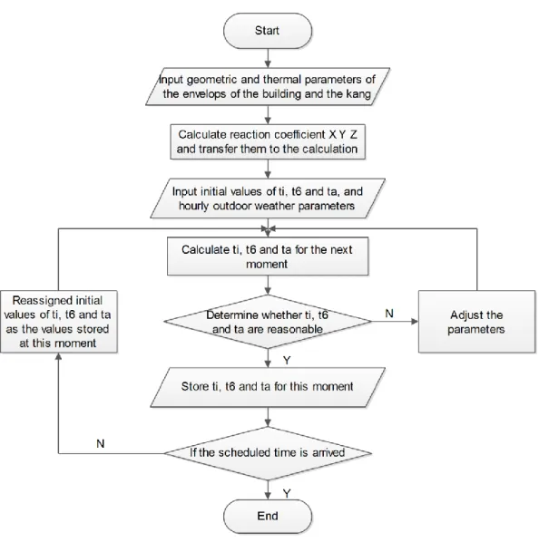
Figure 1-1 Organization of this dissertation ... 5 Figure 2-1 Thermal process diagram of the room with the kang ...10 Figure 2-2 Diagram of the program for calculating temperatures regarding the kang ...
23
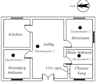
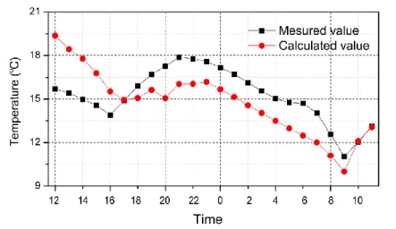
Figure 2-3 Floor plan of the objective building and distribution of thermometers ....25 Figure 2-4 Regression curves of the measured temperatures in 48 hours ...26 Figure 2-5 Calculated value of the temperatures ...29 Figure 2-6 Measured and calculated values of indoor air temperature ...29 Figure 2-7 Measured and calculated values of exterior temperature of the kang’s
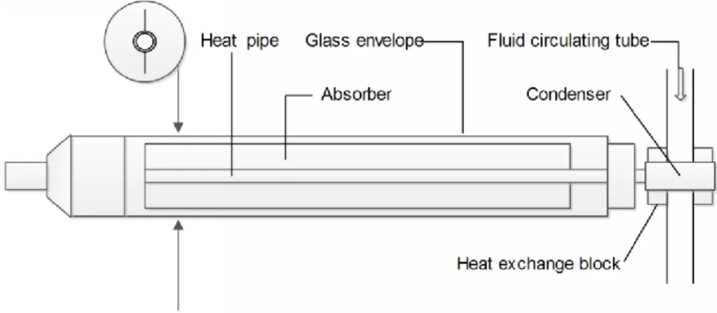
faceplate ...30 Figure 3-1 Equivalent circuit diagram of the photovoltaic module ...35 Figure 3-2 Illuminated I-V sweep curve ...37 Figure 3-3 I-V curve for arrays ...39 Figure 3-4 Daily electricity generation capacity of the selected PV module ...41 Figure 3-5 Daily average efficiency of the selected PV module ...41 Figure 3-6 Detailed arrangement of heat pipe evacuated tubular collector ...42 Figure 3-7 Equivalent thermal network of heat pipe evacuated tubular collector ...44 Figure 3-8 Water and heat flow path of a typical solar thermal collector with an
unstratified water tank ...47 Figure 3-9 Daily heat generation capacity of the selected SWH device ...49 Figure 3-10 Daily average efficiency of the selected SWH device ...49 Figure 3-11 Block diagram of the SOFC device ...50 Figure 3-12 Water and heat flow path of a typical fuel cell device with an unstratified
XXII List of Figures
water tank ... 51 Figure 3-13 Daily average generation capacities of the selected SOFC device ... 54 Figure 3-14 Daily average efficiency of the selected SOFC device ... 55 Figure 4-1 Plan view of the standard building ... 58 Figure 4-2 Elevational and cross-sectional view of the standard building ... 58 Figure 4-3 Hourly average solar radiation in the normal vector of the roof plot by the
data collected from the database (AIJ, 2005) ... 59 Figure 4-4 Hourly average outdoor air temperatures plot by the data collected from
the database (AIJ, 2005) ... 60 Figure 4-5 Hourly temperatures of the municipal water plot by the data collected
from the database (FCWB.WPD, 2004) ... 60 Figure 4-6 Hourly electric power load distribution ... 61 Figure 4-7 Hourly hot water load distribution ... 61 Figure 4-8 Block diagram of the integrated DER device ... 65 Figure 4-9 Process chart indicating the operation modes of electric power and hot
water ... 66 Figure 4-10 Monthly distribution of energy consumption in Case 1... 69 Figure 4-11 Monthly reduction of conventional energy consumption in Case 1 ... 70 Figure 4-12 Monthly distribution of energy consumption in Case 2... 72 Figure 4-13 Monthly reduction of conventional energy consumption in Case 2 ... 73 Figure 4-14 Monthly distribution of energy consumption in Case 3... 75 Figure 4-15 Monthly reduction of conventional energy consumption in Case 3 ... 76 Figure 4-16 Monthly distribution of energy consumption in Case 4... 78 Figure 4-17 Monthly reduction of conventional energy consumption in Case 4 ... 79 Figure 4-18 Comparison of reduction of conventional energy consumption between
cases ... 80 Figure 5-1 Energy transformed and flowing from solar via the DER devices to the load
87
Figure 5-2 Price curves of electric power and natural gas ... 89 Figure 5-3 Convergence curve of the genetic algorithm ... 92 Figure 5-4 Annual quantity of energy distribution aimed at energy conservation using
the optimized integrated system compared with not using ...95 Figure 5-5 Life cycle costs and profits aimed at cost economization using the
optimized integrated system ...97 Figure 5-6 Annual quantity of energy distribution aimed at cost economization using
the optimized integrated system ...99 Figure I Simulation model of the PV module ('pv_array.mdl')...73 Figure II Look under mask of the simulation model of the PV module ...75
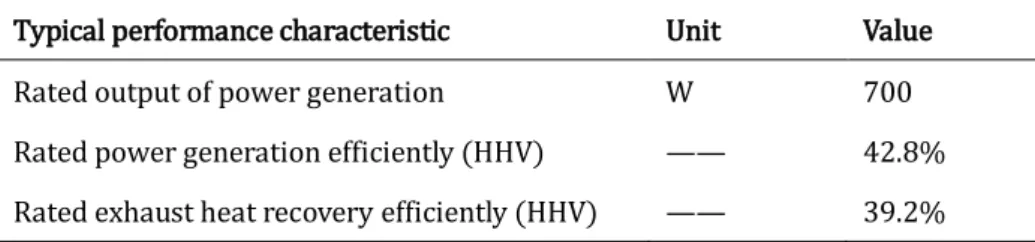
Table 2-1 Independent samples test of measured and calculated values ...31 Table 3-1 Typical performance characteristics of a photovoltaic module ...40 Table 3-2 Typical performance characteristics of a solar thermal collector ...48 Table 3-3 Typical performance characteristics of a generation unit of SOFC device ...
...53 Table 4-1 Expressive equations of electric power distribution to the load and the grid ..
63
Table 4-2 Expressive equations of removing rates of energy distribution to the load ...
...65 Table 5-1 Costs and lifetimes of the system components ...89 Table 5-2 Optimum values of the decision variables aiming at energy conservation ...
...93 Table 5-3 Annual quantity of energy distribution aimed at energy conservation using
the optimized integrated system compared with not using ...95 Table 5-4 Optimum values of the decision variables aiming at cost economization...
...96 Table 5-5 Life cycle cost and profits aimed at cost economization using the optimized
integrated system ...97 Table 5-6 Annual quantity of energy distribution aimed at cost economization using
the optimized integrated system ...98
C HAPTER 1
1. Introduction
ith today’s rapid economic development, increases in the pursuit of comfort have caused the energy demands of humans to grow higher and higher. However, we are fast approaching the peak of our consumption of fossil fuel and are faced with dwindling fossil fuel resources, particularly oil and gas (EIA, 2011). The rapid depletion of fossil fuels and the growing criticisms of nuclear energy will surely lead to shortages of end-use energy supplies if no actions are taken.
Among three main energy consumption sectors in Japan, energy consumption level of commercial and residential sector is growing larger and larger, increasing at a much faster rate than that of the other sectors, which are also increasing very quickly (ANRE, 2010). In order to meet these continuously increasing energy demands of humans, effective actions should be taken. Thus, taking effective actions focusing on the commercial and residential sector brooks no delay, which can be operated by two manners as
W
2 Installed Capacity Optimization in Combination of DER Devices for Residential Buildings
using alternative sources of energy;
increasing efficiency in both the conversion and transport of energy.
1.1 Background
Regarding the use of alternative sources of energy, instead of additional conventional power plants, increasing numbers of central power plants utilizing renewable energy should be established, including solar energy, wind energy, geothermal energy, etc. As for using conventional energy more efficiently, growing numbers of polygeneration plants should be built, since they can attain higher overall efficiencies than traditional plants.
As the above mentioned types of technologies are very diverse, it is important to be able to accurately determine their capacities, in order to efficiently integrate them. In this pursuit, many researchers have targeted the determination of the optimum capacity, according to the energy demands of consumers, to facilitate more economical and efficient power plant operations (Ashok, 2007; Carvalho, Lozano, & Serra, 2012; H. C.
Chen, 2013; Ekren & Ekren, 2010; Groscurth, Bruckner, & Kümmel, 1993; Rubio-Maya, Uche-Marcuello, Martínez-Gracia, & Bayod-Rújula, 2011; H. Yang, Zhou, Lu, & Fang, 2008).
However, construction of these plants usually takes many years, and also improvements of energy efficiency in both the conversion and transportation are considered, thus distributed energy resource (DER) devices for residential use, that can be easily installed and quickly implemented merit promotion. DER devices are defined as small-scale electric power and hot water generation devices used to provide alternative to or enhancement of the traditional power station and hot water boiler in this research.
Therefore, a number of research tasks had been done in dealing with DER devices (Andreadis, Roaf, & Mallick, 2012; Ganguly, Misra, & Ghosh, 2010; Ren & Gao, 2010a, 2010b; Yamaguchi et al., 2012). Since a single DER device is very unlikely to provide
enough electric power and heat in a highly-efficient manner, many researchers have done the tasks in determining the optimum installed capacities of DER devices (Khatib, Mohamed, & Sopian, 2012; Khatib, Mohamed, Sopian, & Mahmoud, 2011; C.-H. Li, Zhu, Cao, Sui, & Hu, 2009; Ren, Gao, & Ruan, 2008; Taghipour Rezvan, Shams Gharneh, &
Gharenpetian, 2013), and furthermore, finding solutions for the operations of them (Y.-H.
Chen, Lu, Chang, Lee, & Hu, 2012; Hamdy, Hasan, & Siren, 2012; Kayo & Ooka, 2010; H. Li, Nalim, & Haldi, 2006; Lozano, Ramos, Carvalho, & Serra, 2009; Ren, Zhou, Nakagami, Gao,
& Wu, 2010).
It can be seen that existing papers have mainly referred to the analysis and optimization of electric power and heat generation, rarely any directly involves hot water demand. However, at the present time, the small-scale photovoltaic (PV) and solar water heating (SWH) devices, which use solar as their energy source, have received plenty of attention in residential use. Additionally, the small-scale solid oxide fuel cell (SOFC) device turns out to be a good choice for residential energy conservation, since it can generate electric power in a highly-efficient manner, and meanwhile supply hot water for residential use. It is well known that a single PV or SWH device is very unlikely to provide a stable electrical or hot water supply, due to the low energy density and high randomness of solar energy. A single SOFC device is unlikely to provide enough end-use energy in a highly-efficient manner, due to its working principles that the generation efficiency diminishes as the load drops, and in this situation the electrical load fluctuates considerably. Thus, there remains significant work to be done, in order to make optimal use of DER devices that would supply not only electric power, but also hot water directly, while additionally reducing conventional energy and life cycle costs. We believe it will be a great benefit for the residents and the society to find an effective way to reduce conventional energy consumption levels, which will result in greater cost efficiencies.
4 Installed Capacity Optimization in Combination of DER Devices for Residential Buildings
1.2 Objectives
Accordingly, this study aims to present an integration and optimization methodology for the optimum capacities determination of DER devices, which include a PV device, an SWH device and an SOFC device.
Initially, the dynamic models of the DER devices are aimed to be built in this research. Appropriate operation strategies for the integration of the electric power and hot water are determined based on the dynamic mathematical models. With the operation strategies determined, combinations of the devices are selected. Energy conservation effect of each combination of the DER devices is analyzed and evaluated.
Followed, a genetic algorithm is tend to be used to determine the optimum capacities of the devices with consideration for their multi-period operations for an entire year, as the optimization in this research is highly complicated due to the uncertainty of solar radiation together with the load demand variability and the nonlinearity of heat loss from the exhausted hot water. The decision variables that need to be optimized include the quantities of the PV module and the SWH collector, the volumes of the SWH tank and SOFC tank, as well as the capacity of the generation unit of the SOFC. The conventional energy consumption and life cycle costs are treated as the optimization objectives in this research, while limitations of decision variables are chosen as constrained conditions.
At last, a case study of a typical residential building located in Fukuoka City in Japan is aimed to be carried out to clarify the simulation process by utilizing specifications of the systems provided by the manufacturers, as well as available weather data, municipal water data, and energy load data calculated by a life style calculation program, and a thermal environment simulation program.
1.3 Organization
As Figure 1-1 shows, overall, this dissertation consists of six chapters, excluding Chapter 1 presents the background and the objectives of this research, and Chapter 6 proposes the synopsis and the prospects, the remaining chapters are mainly written in two main parts. Chapter 2 focuses on the traditional Chinese kang, which takes efficient utilization of energy resource, is the prelude of the subsequent part, and is an inspiration for us to make optimal use of energy in researching on modern energy devices. Chapters 3 to 5 constitute the core of the dissertation, which focus on the DER devices used in residential buildings, and they are progressively related:
Modeling of three selected DER devices, including PV, SWH, and SOFC;
Integration of the models of the selected DER devices using proper operation strategies of electrical and hot water;
Installed capacity optimization of the DER system integrated by the selected DER devices.
Figure 1-1 Organization of this dissertation
C HAPTER 2
2. Chinese Kang
hinese kang use energy in an efficient way and meanwhile improve indoor thermal environment, so that it is an excellent example of energy use filled with the wisdom of ancient Chinese people. Researching on the energy use of Chinese kang can surely help us to make efficient use of energy with modern energy devices.
As a result of the above reasons, this chapter aims to describe the thermal processes of the buildings with Chinese kang and the kang itself, build mathematical models of them, and analyze the calculation results of the field measurements and simulations. By carefully research on the Chinese kang, the energy conservation effect is surely presented and the good experience from Chinese kang can be furthermore used into other kinds of energy devices.
C
8 Installed Capacity Optimization in Combination of DER Devices for Residential Buildings
2.1 Background
At present, rural energy uses in northern China are mainly for cooking and heating, of which heating energy use is the most prominent in winter. According to the survey statistics, the energy consumption in northern rural areas takes up to 56% of the country's total energy consumption, of which more than 80% of rural energy is consumed for heating (X. Yang & Jiang, 2008). If the residential heating in rural areas goes through the same way as that the central heating runs in urban areas, it is neither economic nor realistic. There are many kinds of conventional bioenergy in northern rural areas which is easy to be obtained, especially those remainders for harvesting, i.e.
the straws and other crop residues, which no doubt play a role for the use of waste. And also, according to statistics, the total bioenergy produced every year in rural areas of China, i.e. the straw, firewood, etc., is approximately 6 million tons, of which about 60%
is used as fuel for heating and cooking (J. Li, Bai, & Ralph, 1998). Therefore, the heating methods including the kang which can use the bioenergy for heating are more in line with the rural lifestyle. Meanwhile, it is no doubt a more scientific and rational way to ensure energy heating requirements. Among the various heating methods, the kang is the most widely used form of heating. According to the statistics from Ministry of Agriculture, PRC, there are about 66.85 million kangs existed in China by 2004, which are used by nearly 43.64 million rural households (approximately 175 million people), i.e. every two families have 3 kangs (BERC, 2008). In 2006, according to the research on energy and environment of rural households in northern China by Tsinghua University, the utilization rate of the kang in the north of China is 73.3%, in the northwest, it is 86.3%, and in the northeast, it is up to 96.2%(EEGNRA, 2007).
According to the survey, rural residential areas in the northern China have many problems with indoor air temperature, energy consumption in winter and pollution. The consumption in rural residential areas is up to 30-40 kg/m2 of standard coal, but it can only maintain the indoor air temperature at about 10 °C, which is about twice of that used for urban heating (BERC, 2008). With the improving living standards and urbanization, the prospects of the traditional heating method are not so optimistic in
rural areas. From the 1980s, the commercial energy resources used in the rural areas, i.e.
commercial coal, electricity and natural gas, gradually increase. At present, the consumption of commercial coal, electricity and natural gas have taken up to 60% of the total energy consumption in rural areas in China (X. Yang & Jiang, 2008). In 2006, Li Y.
found that there is a trend that the northern rural areas have a commercial energy based heating mode and is adopting non-commercial energy for heating according to their research on the comprehensive utilization of energy in northern rural areas, i.e.
Heilongjiang, Liaoning and Gansu provinces (Y. Li, Sun, & Yang, 2006). In accordance with this situation, there bound to be heavy pressure on economic and social sustainable development of China. Thus, on basis of the unique characteristics of the rural areas in the north of China, seeking a proper heating method to improve the indoor thermal environment without heavy energy consumption will be an important issue for building energy conservation.
2.2 Outline of thermal process
Kang is not only a heating facility, but also a part of the building. The ultimate goal of this chapter is to analyze its impact for indoor thermal environment. The rooms with kang as the heating method generally do not need active control to adjust the indoor air temperature, and its thermal environment is determined by its dynamic thermal process, thus, according to the systematic research on dynamic thermal process of the room and the kang, the effect that the kang effects on the indoor thermal environment can be quantitatively analyzed in practice.
The indoor thermal environment depends on the equilibrium state of heat transfer, which includes the convection between each interior surface and the indoor air, the radiation between the surfaces, and the conduction from the building envelopes. For kang, the exterior surface temperature of the kang’s faceplate is much higher than the indoor air temperature and the interior surface temperatures of the building envelopes.
The calculation of heat dissipation on the exterior surface of kang’s faceplate should
10 Installed Capacity Optimization in Combination of DER Devices for Residential Buildings
include convection with the indoor air, and radiation with interior surfaces of the building envelopes.
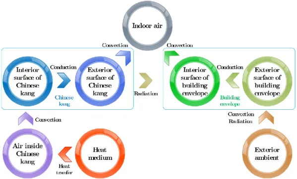
As radiation involves all the interior surfaces, thermal balance equations of every surface need to be established. Thus, the research of indoor thermal environment of kang-heating room is more complex than that of the normal convective heating room. As it is shown in Figure 2-1, the core of the mathematical model of indoor thermal environment of the kang-heating room is the thermal balance equations, composed by the indoor air, interior surface of the building envelopes and exterior surfaces of the kang. The completed model should also include control equations established by the control channel and the interference channel. The control channel is composed of heat medium, air inside the kang, interior surfaces and exterior surfaces of the kang. And the interference channel is composed of exterior ambient, exterior surfaces and interior surfaces of the building envelopes.
Figure 2-1 Thermal process diagram of the room with the kang
2.2.1 Outdoor interferences
Outdoor interferences include outdoor weather conditions (i.e. outdoor ambient temperature, solar radiation, wind speed and direction, etc.) and outdoor thermal environment (i.e. surface temperature of the surrounding ambient, etc.). Notably, the neighboring room's thermal environment can be regarded as an exterior interference for the kang-heating room. The interferences affect the temperatures of the interior surfaces of the room through the building envelopes in the way of conduction, and then affect the indoor air temperature in the way of convection. In addition, as materials of most building envelopes have attenuation and lag effects on the impact from outdoor interferences due to their large thermal resistances and heat capacities, walls, roofing, and flooring should be calculated by the way of unsteady-state heat transfer. However, the windows and doors are thin and have small heat capacities, so that they can be calculated in steady-state way.
2.2.2 Heat transfer of kang
Basically, the kang is the only indoor heating equipment in kang-heating rooms, which can make full use of waste heat of the smoke exported from the stove in order to improve the indoor thermal environment. During the cooking time, air in the kitchen goes into the stove by thermal pressure, the temperature of which become higher heated in the stove, and then it flows through the inside of the kang while heating the plates, subsequently transfers the heat into the room in the way of convection and radiation, and finally flows the whole way to the outdoor from the chimney leaving most of its heat inside the kang. Although there is no high-temperature airflow comes into the kang while we are not cooking, the remaining high-temperature airflow inside the kang constantly transfers heat in a convective and radiative way into the room through the kang’s faceplate. As to prevent the airflow flowing out, maintain the heat inside the kang and slow down the heat loss, the kang is used to be sealed strictly with a smoke flapper when heating is stopped. In a summary, the kang plays the role as a heat transfer staff that the interior surfaces of the kang gain heat by exchanging with the high-temperature
12 Installed Capacity Optimization in Combination of DER Devices for Residential Buildings
airflow inside the kang, and then the heat is transferred into the interior of the room through the exterior surfaces of the kang.
The exterior surface of the kang’s faceplate mainly affects the indoor thermal environment through the convection with the indoor air, as well as the radiation with the interior surfaces of the building envelopes. The convection and radiation performances of the exterior surface of the kang’s faceplate reflect the heating capacity of the kang.
Considering the size and heat transfer characteristics of the kang’s faceplate, convection on the surface of the kang’s faceplate can be dealt with following the way of natural convection of an infinite horizontal plate. In addition, convection on the interior vertical surfaces of the room can be calculated as natural convection of an infinite vertical plate, and radiation on exterior surface of the kang’s faceplate can be calculated by angular coefficient method.
Considering the coupling heat transfer effecting between the interior surfaces of the kang and the airflow flowing through the stove, the kang and the chimney, and the coupling heat transfer effecting among the kang, the indoor air and the interior surfaces of the building envelopes, a macroscopic model is applicable and feasible to be used to analyze the thermal process of the kang.
2.2.3 Indoor interferences
Indoor interferences in the kang-heating room can be divided into two parts as latent heat interference and sensible heat interference. The humidity loss from the human bodies and the equipment is accompanied with the latent heat loss, which directly impact on the enthalpy of the indoor air immediately. The sensible heat from the lighting, the human bodies and the equipment can be separated into two forms. One of the forms is heat transfer with indoor air by convection directly, and the other one is heat transfer by radiation with each surrounding surface, through which the sensible heat will be transferred to the indoor air by convection.
2.2.4 Ventilation
Outdoor air flows into the room and directly intermixes with the indoor air, mainly in the way of natural ventilation or infiltration. The heat and moisture of the outdoor air effect on the indoor air immediately, so that the temperature and humidity of indoor air changes.
Notably, as the main topic in this chapter is the thermal process of the kang, only the air temperature changes affected by the ventilation or infiltration are focused on, and the coupling effect of heat and moisture transfer are not considered.
2.3 Mathematical modeling 2.3.1 Kang-heating room
The dynamic thermal process can be divided into the following sections for creating the equations:
Thermal balance equation of indoor air
Thermal balance equations of interior surfaces of envelopes
Thermal balance equations of exterior surfaces of envelopes
Control equations of heat transfer through envelopes
Among these four sections, only three of which are needed to form the final equations, as they are repeated for some extent. Thermal balance equation of indoor air, thermal balance equations of interior surfaces of envelopes, and control equations of heat transfer through envelops are selected for building the equations
14 Installed Capacity Optimization in Combination of DER Devices for Residential Buildings
1) Thermal balance equation of indoor air
The indoor air temperature of kang-heating room is a function of the spatial and time coordinates, which is usually calculated by the
Lumped Heat Capacity Method
for simplicity. With latent heat of human-beings and heat transfer from the phase transition of the indoor air ignored, the thermal balance equation is made as( ) ( ) ( ) ( ) ( )
i
i p i c V G F
V c dt Q Q Q Q
d
(2.1) whereVi is the volume of the indoor air, m3;
cp is the specific heat of the indoor air, J/(kg·K);
i is the density of the indoor air, kg/m3;
c( )
Q is the convective heat exchange between the interior surfaces of the building envelopes and the indoor air at the time of
, J/h;V( )
Q is the heat exchange by infiltration between the indoor and outdoor air at the time of
, J/h;G( )
Q is the heat exchange by natural convection between the indoor and outdoor air at the time of
, J/h;F( )
Q is the heat gain from indoor anthropogenic sensible heat and the lighting (constant value, changing by the actual conditions) at the time of
, J/h.2) Thermal balance equations of interior surfaces of envelopes
It is assumed that there is no phase changes existing in the envelope structure, thermal parameters are constant, heat exchange by the permeability of the water vapor inside the envelope structure is not considered, the indoor air flows sufficiently, and it can be thought as a lumped heat capacity system, with the heat gain direction of the interior surface of the building envelope acts as the positive direction, thus, the thermal balance equation explaining the interior surfaces of the building envelopes can be built as
( ) ( ) ( ) ( ) 0
cj rj sj j
Q Q Q Q (2.2) where
cj( )
Q is the convective heat exchange between the jth interior surface of the building envelope and the indoor air at the time of
, J/h;rj( )
Q is the radiative heat exchange between the jth interior surface of the building envelope and the other interior surfaces at the time of
, J/h;sj( )
Q is the heat gain from the interior surfaces of the building envelopes by solar radiation (appears only when solar radiation) at the time of
, J/h;j( )
Q is the heat exchange between the jth exterior surface of the building envelope and the outdoor ambient through building envelopes at the time of
, J/h.3) Control equations of heat transfer through envelopes
Heat transfer control equations should be led into the calculation of mathematical model of the kang-heating room. It can be divided into 3 categories according to the heat transfer characteristics of the building envelopes, which are respectively discussed below.
Finite thickness plates (Roofing and walls)
The types of the exterior building envelopes are various, as well as a large amount of boundary conditions, so that it cannot be calculated easily. As a result of the homogeneity in the direction of thickness, and that the value of thickness is much smaller than that of length and width, heat transfer control equation is usually simplified as one-dimensional unsteady-state heat transfer equation as
2 2
( , ) ( , )
w w
w w w
t x t x
c x
(2.3) wherew is the density of the building envelope, kg/m3; cw is the specific heat of the building envelope, J/(kg·K);
16 Installed Capacity Optimization in Combination of DER Devices for Residential Buildings
w is the thermal conductivity coefficient of the building envelope, J/(m·K·h);
( , )
t xw is the instantaneous temperature along the thickness of the envelope at the time of , oC.
The boundary condition of the interior surface of the building envelope is actually the heat transfer with the outdoor ambient at the instant time. Based on
Fourier’s Law
, there is equation as( , ) j( )
w w
in j
t x Q
x F
(2.4) where, Fj is the area of the jth building envelope, m2.
The boundary condition of the exterior surface of the building envelope is actually determined by the thermal balance of itself. Based on
Fourier’s Law
, there is equation as( , )
[ ( ) ( )]
w
w ecj z ej
out
t x t t
x
(2.5) where
ecj is the convective heat transfer coefficient of the exterior surface of the jth envelope, J/(m2·K·h);
z( )
t is the outdoor sol-air temperature at the time of
, °C;ej( )
t is the temperature of the exterior surface of the jth envelope at the time of
, °C.There are so many kinds of methods for solving these equations, including C.O.
Mackey and L.T. Wright's equivalent temperature method (US), A.M. Шкловер’s harmonic reaction coefficient method (former Soviet Union), Carrier company's thermal storage coefficient method (US), D.G. Stephenson and G.P. Mitalas's thermal reaction coefficient method (Canada), and the derived thermal reaction coefficient method of room and Z transfer function method, etc.
The thermal reaction coefficient method is adopted in this study, by which the exchanging heat power between interior surfaces of the building envelopes and the outdoor ambient at the instant time can be calculated as (Yan & Zhao, 1986)
0 0
( ) ( ) ( ) ( ) ( )
j j j z j j j
u u
Q
F Y u t
u F Z u t
u
(2.6)where
j( )
Y u is the reaction coefficient of heat transfer of the jth envelope, J/(m2·K·h);
( )
tz u is the outdoor sol-air temperature at the time of u, °C;
j( )
Z u is the reaction coefficient of heat absorption of the interior surface of the jth envelope, J/(m2·K·h);
( )
tj u is the temperature of the interior surface of the jth envelope at the time of
u, °C.
Liu J. separates and derives the thermal reaction coefficient into two categories, according to whether the thermal reaction of the air boundary layer of the interior surface is considered or not (Liu, 1998). In this study, not only the indoor air temperature should be calculated, but also the temperature of each interior surface of the envelope should be calculated, thus, the above selected thermal reaction coefficients are all belonging to the second class without considering the thermal reaction of the air boundary layer of the interior surfaces.
Semi-infinite thickness plate (Flooring)
Heat transfer of flooring is more complex than that of walls, roofing, windows and doors, because the heat transfer of flooring involves heat transfer in soil, rather than in air, which has relationships with soil properties and other factors. The flooring is semi-infinite, if the accuracy is required, one-dimensional unsteady heat transfer method as used in the exterior walls cannot be used. Chen Q. proposed a method of adding heat flow into the calculation of the heat transfer of flooring (Q. Chen, 1988). Although it is an approximate algorithm and only used for steady-state heat transfer calculation, this
18 Installed Capacity Optimization in Combination of DER Devices for Residential Buildings
method can basically reflect the heat transfer principle of flooring. Considering the condition of the climates, elevation difference of indoor and outdoor flooring and the construction of the flooring, this method is a relatively more accurate algorithm compared with the others.
Taking into account the complexity and difficulty on simplifying the calculation of two-dimensional calculation, the heat transfer of flooring is simplified as semi-infinite one-dimensional non-steady state heat transfer in this study. As simplified like this, heat transfer equation of the flooring will be the same as that of the roofing and the walls, but only with the boundary condition changed, and the boundary condition in the infinite distance can be calculated as
( , )
t t (2.7) where, t is the temperature of infinite depth of the shallow ground, °C.
When the shallow ground reaches a certain depth, its temperature is closed to the constant temperature, which is approximately equal to the long year annual mean temperature. As the heat transfers to the room from infinite distance, there is hardly any heat exchange with interior surfaces of the ground. Therefore, heat transfer between the interior surface of the flooring and the infinite depth of shallow ground at an instant time also can be calculated by using thermal reaction coefficient method. The equation of which is made as
0
( ) U ( ) ( )
j j j j
u
Q
F Z u t
u
(2.8)
Lightweight building envelope (Door and window)
For doors, windows and other lightweight building envelopes, the thermal storage effect can be ignored due to their small heat capacities, so that the steady-state calculation method is adopted. There is control equation as
( ) [ ( ) ( )]
j j e i j
Q
K t
t
F (2.9) whereKj is the heat transfer coefficient of the jth lightweight building envelope (considered heat transfer coefficient of the surface), J/(m2·K·h);
e( )
t is the outdoor air temperature at the time of
, °C;i( )
t is the indoor air temperature at the time of
, °C.2.3.2 Chinese kang
The traditional ground kang is adopted as the target for calculation. As for simplify, the sidewalls of the kang are considered as two kinds, one kind of which towards the inside, the other kind of which faces outside of the room. Good insulation measures are adopted between the kang and building envelopes, so that the process of the heat exchange of the sidewall facing outside can be thought as steady-state heat transfer. Considering the consistency of the calculation, the heat transfer happens in the sidewall facing inside are thought as unstable heat transfer.
1) Thermal balance equation of the air inside the kang
As the heat produced by the air phase change ignored, the thermal balance equation is made as
( ) ( ) ( )
a
a p a kc kG
V c dt Q Q
d
(2.10) whereVa is the volume of air inside the kang, m3;
cp is the specific heat of the air inside the kang, J/(kg·K);
a is the density of the air inside the kang, kg/m3;
kc( )
Q is the heat exchange between the interior surfaces of the kang and the air inside the kang at the time of
, J/h;20 Installed Capacity Optimization in Combination of DER Devices for Residential Buildings
kG( )
Q is the difference of the convective heat gain from inlet port of the kang and heat loss from outlet port of the kang, i.e. instantaneous heat gain from the heat medium inside the kang (ignoring heat loss by building envelopes in the process of exhausting) at the time of
, J/h.2) Thermal balance equation of the interior surfaces of the kang
It is assumed that there is no phase changes existing in the kang structure, thermal parameters are constant, heat exchange by the permeability of the water vapor inside the kang structure is not considered, the air flows sufficiently inside the kang, and it can be thought as a lumped heat capacity system, with the heat gain direction of the interior surface of the kang acts as the positive direction, thus, the thermal balance equation explaining the interior surfaces of the kang can be built as
( ) ( ) ( ) 0
kcn krn k n
Q Q Q (2.11) where
kcn( )
Q is the convective heat exchange between the nth interior surface of the kang and the air inside the kang at the time of
, J/h;krn( )
Q is the radiative heat exchange between the nth interior surface of the kang and other interior surfaces at the time of
, J/h;k n( )
Q is the heat exchange between the nth interior surface of the kang and the indoor air through envelopes of the kang at the time of
, J/h.3) Control equations of heat transfer through kang’s envelopes
The kang transfers heat through the faceplate, the exterior heat transfer of which includes convection with the indoor air and radiation with other surfaces of the interior building envelopes, the interior heat transfer of which includes the convection with the airflow in the kang and radiation with other interior surfaces of the kang. Since the thickness of the faceplate is much smaller than its length and width, heat transfer of the kang can be considered as one-dimensional non-steady state heat transfer, thus the
complete mathematical description is as
2 2
( , ) ( , )
k k
k k k
t x t x
c x
(2.12) where
k is the density of the kang’s structure, kg/m3;
ck is the constant pressure specific heat of the kang’s structure, J/(kg·K);
k is the thermal conductive coefficient of the kang’s structure, J/(m2·K·h);
( , )
t xk is the instantaneous temperature along the kang’s thickness at the distance of x, at the time of
, °C.The boundary condition of the interior surface of the kang is actually the heat transfer with the indoor air at the instant time. Based on
Fourier’s Law
, there is an equation as( , ) ( )
k k n
k
in n
t x Q
x F
(2.13) where,Fn is the area of the nth surface of the kang, m2.
The boundary condition of the exterior surface of the kang is actually determined by the thermal balance of itself. Based on
Fourier’s Law
, there is equation as( , ) ( ) ( ) ( )
k cn rn sn
k
out n
t x Q Q Q
x F
(2.14) where
cn( )
Q is the convective heat exchange between the nth exterior surface of the kang and the indoor air at the time of
, J/h;rn( )
Q is the radiative heat exchange between the nth exterior surface of the kang and other interior surfaces of the kang at the time of
, J/h;sn( )
Q is the heat gain of the nth exterior surface of the kang by solar radiation at the time of