Doctoral Thesis
Shibaura Institute of Technology
Dynamic Analysis of Transfemoral Prosthesis
Function using Finite Element Method
March 2020
A DISSERTATION SUBMITTED TO THE GRADUATE SCHOOL OF ENGINEERING AND SCIENCE OF
SHIBAURA INSTITUTE OF TECHNOLOGY
by
MOHD SYAHMI BIN JAMALUDIN
IN PARTIAL FULFILLMENT OF THE REQUIREMENTS FOR THE DEGREE OF
DOCTOR OF ENGINEERING
iv
To my mother, for everything she has given to me.
To my wife and my two-little daughters, for their love and
expectation.
v I owe a deep sense of gratitude to all kindnesses and supports for my studies. Like once said that no one succeeds all by themselves, the work would not have been completed without the help of many individuals.
Firstly, I would like to express my sincere gratitude to my advisor Prof. Akihiko Hanafusa for the continuous support of my Ph.D study and related research, for his patience, motivation, and immense knowledge. His guidance helped me in all the time of research and writing of this thesis. I could not have imagined having a better advisor and mentor for my Ph.D study.
Besides my advisor, I would like to thank the rest of my prosthetic and orthotics committee: Prof. Yamamoto Shinichirou, Prof. Yukio Agarie, Prof. Hiroshi Otsuka, and Prof. Kengo Ohnishi for their insightful comments and encouragement, but also for the hard question which incented me to widen my research from various perspectives.
I thank my fellow lab mates in for the stimulating discussions, for the sleepless nights we were working together before deadlines, and for all the fun we have had in the last three years. Also, I thank my friends in the Malaysian Community in Shibaura Institute of Technology (SIT) for their support and encouragement during my time in the university
I would like to thank to SIT for granted myself a scholarship through these 3 years of the study. With the financial support, I can complete this study with flying colour and able to focus during performing the whole research.
Last but not the least, I would like to thank my family: my mother and to my brothers and sister for supporting me spiritually throughout writing this thesis and my life in general. Moreover, those achievements of mine could not be attained without the presence of my wife, who has always been by my side and has given me strength to overcome the difficulties during these three years of hard working.
vi activity. It is also used to help an amputee to overcome their lack of confident because of the disability and help to improve their quality of life (QoL) from post-traumatic accident. The demand of prosthetic device in recent years has increased and it was driven by increasing the number of amputees in around the world. The high demand of the device gives an opportunity to the fabricator to increase their prosthetic device fabrication. However, due to extensive time used during fabricating the socket and lack of expertise in the prosthesis and orthotic (PO) field, fabricator cannot achieve the demand. In conjunction of the matter, engineer and prosthesis has provide an assistive method to reduce the time consume during the socket fabrication. A pre-fabrication analysis by quantitative measurement was proposed to develop an evaluation system for improving the existing prosthetic device fabrication. In the study, utilization of finite element method (FEM) to conduct the quantitative evaluation of transfemoral prosthetic socket has been proposed. The study consists of analysis the accuracy of the Magnetic Resonant Imaging (MRI) based three-dimensional (3D) model used in the simulation, analysis of the geometrical deformation of the residuum during interaction with socket and analysis of the pressure distribution occurred inside the socket during various situation. The finding of the study suggests FEM can be classified as an alternative method to evaluate the pre-fabrication prosthetic device. FEM can help the engineer and prosthesis to design the prosthetic device according to subject comfortability without undergone the preliminary socket fitting session. Furthermore, with the pre-fabrication evaluation system, the intervention of prosthesis can be reduced together with the fabricating time. The study includes with seven chapter structured as follow:
Chapter 1: Introduction
This chapter provides an outline of the whole work. The background study will be elaborate in this chapter. The introduction of transfemoral prosthesis, finite element method and the relationship between proposed study with the real-world activity will be elaborated. The objective, scope of study, limitation of the study also will be clarified in this chapter.
Chapter 2: Literature and Technical Review
vii Residuum Model
This chapter present an evaluation towards 3D reconstructed model of residuum. This chapter explain the important of the model accuracy towards providing an alternative method replacing the actual human experiment. The accuracy of the model will be evaluated based on the relationship between number of intersections point during constructing the model and the volumetric value of the model.
Chapter 4: Evaluation on Effect of Geometrical Changes of Prosthetic Socket Towards Transfemoral Residuum Model
This chapter present the evaluation on the effect of prosthetic socket changes towards residuum. The study focusing on evaluating two type of prosthetic socket. The geometrical shape of residuum and the socket consider to be differed to enhance the contact surface between both of it. The geometrical changes were observed during complete stage of donning simulation. The evaluation result is an important key toward improving an accuracy of the model design.
Chapter 5: Analysis of The Pressure Distribution Inside Prosthetic Socket in Various Situation.
This chapter presents a pressure distribution analysis occurred in prosthetic socket. The pressure measured in donning process simulation and gait cycle simulation. The 3D model created in the simulation were MRI based. The models were pre-determined with dynamic parameter that based on previous study. The result then compared with actual experiment data conducted from previous study. The result showed high correlation between simulation and experiment measurement.
Chapter 6: Evaluation System for Magnetic Resonance Imaging (MRI) Based Three-Dimensional (3D) Modelling of a Transfemoral Prosthetic Socket Using Finite Elements Method
ix
Nomenclature
Roman Symbols
3D→Three Dimension
AD→Anterior Distal
AKA→Above Knee Amputation
AP→Anterior Proximal
CAD→ Computer Aid Design
CAT-CAM→ Contour Adducted Trochanteric Controlled Alignment
Method
COP→ Centre of Pressure
FE→ Finite Element
FEA→ Finite Element Analysis
FEM→ Finite Element Method
GRF→ Ground Reaction Force
HFE→ High Frequency Events
x
MD→ Medial Distal
MP→ Medial Proximal
MRI→ magnetic resonance image
NRCD→ National Disabled Persons Rehabilitation Centre
PD→Posterior Distal
PP→ Posterior Proximal
UCLA→ University of California Los Angeles
UK→ United of Kingdom
Dedication………... ii
Acknowledgement………. iii
Abstract………... iv
Nomenclature………... vii
List of figures……….. x
List of tables……… xii
1 Introduction………. 1
1.1 Background Study……….. 1
1.1.1 Overview of Amputation Issues……….. 1
1.1.2 Solution of The Amputation………. 3
1.2 Introduction to Transfemoral Prosthesis Device……… 5
1.2.1 Prosthetic Device Management for Transfemoral Amputation……….. 6
1.2.2 Prosthetic Socket………. 7
1.2.3 Transfemoral Suspension System………. 9
1.2.4 Prosthetic Knee Units………. 10
1.2.5 Prosthetic Foot………. 11
1.3 Common issue in transfemoral prosthesis industry 1.3.1 Increment of transfemoral amputation number……. 12
1.3.2 Evaluation of prosthetic socket in pre and post fabrication………. 13
1.3.3 Transfemoral Prosthesis Research Difficulty 15 1.4 Research Objectives………. 16
1.5 Structure of the dissertation………... 18
1.6 Scope of Study 19 2 Literature and Technical Review……….. 20
2.1 Technical Review 2.1.1 B-spline Interpolation………. 20
2.1.1.1 Bezier Curve Interpolation……… 20
2.1.2 Finite Element Method………... 24
2.1.2.1 Finite Element Solution of Mathematical Model Theory………. 24
2.1.2.2 Nonlinear Analysis in Finite Element Method……….. 25
2.1.4.2 Constraint……….. 32
2.1.4.3 Contact Definition……… 32
2.1.4.4 Loading Definition……….. 33
2.2 Literature Review 33 2.2.1 Accuracy of 3D Modelling……….. 33
2.2.2 Transfemoral Prostheses Socket Function……… 34
2.2.3 Pressure Distribution in Prostheses Socket………….. 35
2.3 Conclusion………. 36
3 Accuracy Evaluation on 3D Reconstruction of Transfemoral Residuum Model……….. 37
3.1 Introduction……….. 38
3.2 Three-Dimensional Model Construction Methodology………. 40
3.2.1 Magnetic Resonant Imaging (MRI) Data Collection... 40
3.2.2 Pre-segmentation……….. 41
3.2.3 Segmentation………. 42
3.2.4 3D Model Construction………... 43
3.3 Evaluation of the Residual Limb Model………... 44
3.4 Accuracy Evaluation Result……… 45
3.5 Discussion……….. 46
3.6 Conclusion………. 47
3.7 Future Reference………... 48
4 Evaluation on Effect of Geometrical Changes of Prosthetic Socket Towards Transfemoral Residuum Model……… 49
4.1 Introduction………... 50
4.2 Finite Element Simulation and Method of Evaluation………... 53
4.2.1 Three Dimension (3D) Model Construction…………. 53
4.2.2 Simulation Environment………. 54
4.2.3 Clinical Experiment………. 55
4.3 Finite Element Simulation Outcome………. 57
4.4 Discussion………. 60
4.5 Conclusion………. 62
4.6 Future Work……….. 63
5 Analysis of The Pressure Distribution Inside Transfemoral Prosthetic Socket in Various Environment………... 64
5.1 Introduction………... 65
Simulation………. 70
5.2.3 Experimental Analysis……… 71
5.3 Quantitative Evaluation of Finite Element Donning Simulation………. 73
5.4 Analysis of the Simulation……….. 79
5.5 Pressure Analysis Summary……….. 81
6 Evaluation System for Magnetic Resonance Imaging (MRI) Based Three-Dimensional (3D) Modelling of a Transfemoral Prosthetic Socket Using Finite Elements Method……….. 82
6.1 Introduction……….. 83
6.2 System Evaluating Method……… 86
6.2.1 Finite Element Model Construction………. 87
6.2.2 Simulation Environment……… 88
6.2.3 Mechanical Properties of Material for Residuum and Socket………. 89
6.2.4 Simulation and Acquisition Outcomes……… 89
6.3 Simulation Result and Comparative Evaluation of the System 90 6.4 Discussion………. 96
6.4.1 Geometrical Changes………. 96
6.4.2 Error Analysis………. 100
6.5 Summary of the Evaluation System……….. 102
7 Conclusions and Future Works………. 103
7.1 Conclusion………. 104
7.2 Future Work……….. 105
7.2.1 Walking Gait Simulation Proposal 106 7.3 Contribution of The Research 119 References………. 120
x
Figure Title Page
1.1 Level of Amputation (NRCD - Japan) 4
1.2 Athletes with transfemoral amputation run in natural
pattern (Ottobock Ltd.) 5
1.3 Main components of the lower limb prosthesis (NRCD
Japan) 6
1.4 Comparison of the design of the transfemoral socket 7
1.5 A cross section for a transfemoral socket 8
1.6 The IRC socket created by Professor Yukio Agarie 9
1.7 Subject donning a suction socket using a pull sock 10
1.8 The hydraulic prosthetic knee 11
1.9 Conventional prosthetic socket fabrication 13
2.1 Computing a point on a cubic spline curve 19
2.2 Illustration of nonlinear analysis types 24
2.3 FEA Pre-processing 26
2.4 FEA Post-processing 26
2.5 Creo Parametric environment and GUI 27
2.6 GUI of LS-Prepost 29
3.1 Residual Limb model created by LifeMODTM 35
3.2 Geometry Model of residual limb [44] 36
3.3 Completed Residual surface by Arun Dayal [30] 36
3.4 Process of stacking MRI data in z-axis 39
3.5 Process of segmentation 40
3.6 3D model constructed base on MRI data 41
3.7 Comparison of total volume of each model for every
amputee 42
3.8 Average error of volume for each amputee with different
spline point models 43
3.9 Error percentage of volume against height for amputee B 44
4.1 The actual transfemoral prosthesis socket 48
4.2 3D model of MCCT and UCLA socket 49
4.3 Simulation environment with parameter description 52
4.4 Experiment Diagram 53
4.5 Location of triaxial force sensor in the socket 54
xi
5.1 Zone of injury in lower limb injury 62
5.2 Process of creating the MRI image 65
5.3 Multi material 3D model of residuum 66
5.4 An overview of simulation environment 68
5.5 Bi-pedal stance experiment 69
5.6 Comparison of pressure distribution in simulation and
experiment 71
5.7 Correlation coefficient result 72
5.8 Pressure mapping of residuum during complete donning 73 5.9 Illustration of contact surface between tri-axial force sensor
and residuum skin 75
6.1 Conventional method of socket manufacturing 78
6.2 3D printed finger prostheses [86] 79
6.3 3D printed arm forged (PrinterPrezz) 80
6.4 Profile at the cross section from distal end 82
6.5 Simulation boundary condition 83
6.6 Initial position of FEA simulation 86
6.7 Sample of binary image created from subject A 87
6.8 Volumetric value of all parts in every layer for each
subject. 88
6.9 Heat map of a residuum deformation 90
6.10 Variations of the volumes of deformed soft tissue 91
6.11 Error distribution of soft tissue volume 94
6.12 Comparison of average error for every tested model 95
6.13 Graphical comparison of FEA model and MRI data 96
7.1 Subject with a marker in the Mac3D motion capture system 107
7.2 video analysis in the Kinovea software 108
7.3 coordinate system based on the video analysis 109
7.4 Joint angle of a hip during walking gait 109
7.5 Joint angle of a knee during walking gait 110
7.6 Joint angle of an ankle during walking gait 110
7.7 Angular displacement of the hip-knee link 111
7.8 Angular displacement of the knee-ankle link 111
7.9 right amputee knee model for gait simulation in
LS-Prepost environment. 112
xii
7.13 Pressure Distribution in anterior view 115
7.14 Pressure Distribution in posterior view 115
7.15 Pressure Distribution in medial view 115
xiii
Table Title Page
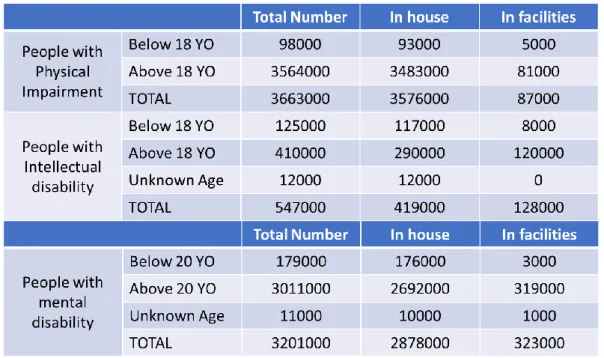
1.1 Data of people with disability in japan recorded at 2014 2
2.1 Classification of nonlinear analysis [26] 23
3.1 Profile of amputees 37
3.2 MRI image specifications 38
3.3 Creo 3.0 features 39
4.1 Mechanical properties of viscoelastic material (one part) 51 5.1 Mechanical properties of viscoelastic material (skin, fat,
muscle parts) 66
6.1 List of element and nodes unit 86
6.2 Subject profiles 86
6.3 Correlation coefficient value of residuum volume 89
7.1 Material Properties 113
1
Chapter 1
Introduction
In this chapter, the introduction of transfemoral prosthetic device will be explained. The introduction involves a briefing of related component in the device, history of transfemoral prosthetic device, briefing of current situation of prosthetic device inside and outside Japan and Malaysia and statistical analysis of amputees in Japan in recent years. The issues or problem related to the prosthetic device will be explained briefly. In other section, the objective of the study will be explained together with the scope of the study.
1.1 Background Study
1.1.1 Overview of Amputation Issue
Amputation is not a new thing in this era. In fact, the amputation has been discovered for a long time ago. For instant, artificial limbs of some type, such as a forked stick, have been used since the beginning of mankind, but the earliest recorded use of a limb prosthesis is that of a Persian soldier who was reported by Herodotus to have escaped about 484 B.C. from stocks by cutting off one of his feet and replacing it with a wooden one [1]. The Amputee Coalition of America estimates that there are 185,000 new lower extremity amputations each year just within the United States [2] and an estimated population of 2 million American amputees [3]. It is projected that the amputee population will more than double by the year 2050 to 3.6 million.
2 is for physical impairment. Internal disorders are said to be 30.5% (1.01 million). Physical disabled people were recorded has more than half of the total disabilities shown in Table 1.1. The data collected from a survey done by Ministry of Health, Labor and Welfare of Japan.
Table 1.1 Data of people with disability in Japan recorded at 2014.
3 According to World Health Organization (WHO) [10], 0.5% of the population of a developing country have a disability that will require a prosthesis or orthosis and related rehabilitation services. This prediction suggests that around 160,000 of Malaysia’s current population of 32 million [11] need prosthetic or orthotic devices. The population is projected to reach 38.5 million by 2040 [11], including approximately 200,000 individuals with a physical disability. The main causes of the amputation are due to diabetes mellitus disease where 17.5% increment of diabetes patient recorded in 2006 [12]. According to scientific study [13], diabetes mellitus is a key risk factor leading to lower limb amputation such that in 2005, the loss of a lower limb due to diabetes was estimated to occur every 30 seconds somewhere in the world [14]. In Malaysia, the National Limb Fitting Centre was created to provide a service regarding the prosthetic and orthotic throughout the nation. However, the centre acting as one centre stand alone and it its suggested to provide optimum access to prosthetic service by developing the centre at national, state and district level [10].
Even though the amputation in Malaysia is not critical compared with other ASEAN country, the government take a proactive action to emphasising the issue. It is estimated around Malaysian Ringgit (RM) 4000 to RM 15000 of price to own a prosthetic socket and it is expensive considering minimum average salary of Malaysian is RM 1100 [15]. The cost of prostheses is a major issue in Malaysia and Malaysia Ministry of Health with collaboration with welfare department and social security organisation has initiate `Tabung Bantuan Perubatan’ (Medical Aid Fund) to help amputee owning the prosthetic device. The lack of structured prosthetic service management system leads to reimbursement issues which increase the waiting period for amputees to be fitted with a prosthesis. These constraints are likely to remain as major obstacles to improving the nation’s prosthetic service unless there are substantial changes in government policies to achieve mutual concordance concerning prosthetic services [15].
In the most developed nations the annual incidence of foot ulceration, which precedes amputation in 85% of cases, is about 2%. In poorer, developing nations a lack of access to care places about half of all persons with diabetes at risk for foot ulceration, and diabetes-related amputations are very common [16]. Yet, the vast majority of amputations both in the US. and abroad are preventable.
1.1.2 Solution of The Amputation
4 prosthetic device is an artificial substitute or replacement of a part of the body such as a tooth, eye, a facial bone, the palate, a hip, a knee or another joint, the leg, an arm, etc. A prosthesis is designed for functional or cosmetic reasons or both. Typical prostheses for joints are the hip, knee, elbow, ankle, and finger joints. Prosthetic implants can be parts of the joint such as a unilateral knee. Joint replacement and arthroplasty mean the same thing.
The amputation divided in two parts which are upper and lower limb amputation. Lower limb amputation categorized in number of different levels as shown in figure 1.1. The most common amputation occurred in United Kingdom was transtibial amputation [18]. Numbers of factors are necessary to decide the ideal prosthetic device according to the level of amputation such as healing potential, rehabilitation potential, prosthetic consideration and discharge arrangement [19].
Figure 1.1 Level of Amputation (NRCD - Japan)
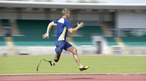
5 approximate anatomy of lower limb, suspension systems enhance and maintain intimate residuum contact within the socket and dynamic prosthetics feet and knee component offer improved, energy-efficient function. The result has been a significant improvement in quality of gait, allowing more people with transfemoral amputation to walk comfortably and naturally with their prosthesis. In addition, athletes with amputation can run in a natural “step-over-step” pattern with a higher degree of stability and comfort than previous possible. The future of people with transfemoral amputation is bright where a lot research has been conducted to improve in many aspects such as the aero dynamic of the socket, knee joint mechanism, prosthetic stability according to work scope and time consume to fabricate the prosthetic socket.
Figure 1.2 Athletes with transfemoral amputation run in natural pattern (Ottobock Ltd.)
1.2 Introduction to Transfemoral Prosthesis Device
Transfemoral prosthesis device was define as a device used by people with above knee amputation to assist their ADL activities especially their walking gait. The device also helps the amputee to regain their self-confident after their traumatic accident. With the device people with amputation can live like a normal people and merge in the committee on their neighbourhood. Most of the amputee has so much support from their family and the government in every country are determined to help this unfortunate group.
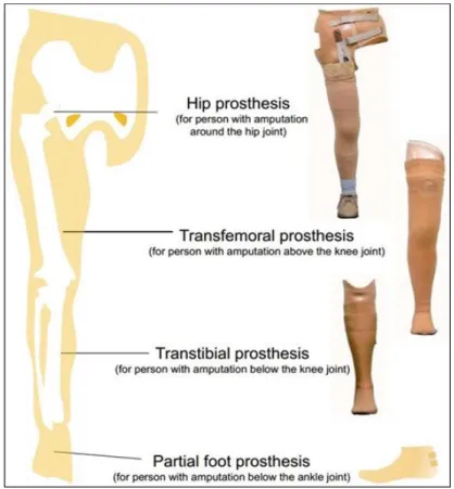
6 three basic mechanism for lower limb prostheses device which are hip prosthesis, transfemoral prosthesis and transtibial prosthesis. Each of the device have a different component to adapt the walking mechanism handled by each amputee.
Figure 1.3 Main components of the lower limb prosthesis (NRCD Japan). Hip prosthesis (left); Transfemoral prosthesis (middle) and Transtibial prosthesis (right)
1.2.1 Prosthetic Device Management for Transfemoral
Amputation
An amputation proximal to the anatomical knee joint is referred to as a transfemoral (above knee) amputation. The transfemoral residual limb varies in length, depending on how much of the femur has been retained. The shape of the residual limb is likely to be a tapered cylinder so that donning a prosthesis is less difficult. Suspension can be challenging, however, as a result of this cylindrical shape of the residuum. The fleshiness of the transfemoral residuum present an opportunity for suction suspention.as the length of the residuum decreases, socket suspension and control of the prosthetic knee become more problematic.
7
1.2.2 Prosthetic Socket
The socket serves as the interface between the residuum and the prosthesis. The type of socket takes an important role in determining the comfortability of amputee during wearing the socket. There are several type of prosthetic socket used by the amputee for specific amputation and for transfemoral amputation, there are four type of prosthetic was commonly used by the amputee which are quadrilateral (quad) socket, ischial-ramal containment (IRC) socket, the Marlo Anatomical Socket (MAS), and subischial socket shown in figure 1.4 and figure 1.5 showed the cross section for each of the socket.
Figure 1.4 Comparison of the design of the quadrilateral (quad) socket (A), the ischial-ramal containment (IRC) socket (B), the Marlo Anatomical Socket (MAS) (C) and
8 Figure 1.5 A cross section for (A) quad socket; (B) IRC socket; (C) MAS; (D) subischial
socket
From the cross section, the different between each socket can be describe where for quad socket, it has a narrow anteroposterior dimension while for IRC socket and MAS, they have narrow mediolateral dimension and for subischial socket, it has a more oval shape which is consistent with the shape of the proximal. The degree to which the prosthetic socket design can influence the position of the transacted femur has been hotly disputed. Many researches have been conducted to understand the relation between alignment, socket design and femoral adduction. In [21], the researcher concluded that the prosthetic socket cannot provide enough lateral pressure to change the position of femur. However, there is also consensus that indicates that an intimately contoured socket in optimal alignment enhances an individual`s gait, decrease energy expenditure, increase socket comfort, and improves overall function [22].
9 Figure 1.6 The process of IRC socket fabrication by Professor Yukio Agarie. The Blue arrow is process of UCLA socket fabrication and the red arrow is a process
IRC-MCCT socket fabrication.
1.2.3 Transfemoral Suspension System
Keeping the prosthesis on in its optimal functional position is more challenging for individual with transfemoral amputation than with transtibial amputation. The suspension system uses to keep a prosthesis device from falling off the residuum. The system can be categorized into the following:
• Self-suspension of the socket - This makes use of the anatomic shape of the residual limb (Syme or knee disarticulation).
• Suction suspension - Methods of creating suction suspension include the use of an appropriate suction socket design, of a gel suspension liner.
• Suspension device or harness - Such equipment includes belts, cuffs, wedges, straps, and sleeves.
10 strong enough to suspend the socket on the residuum develops inside the socket. This form of suspension allows excellent proprioceptive feedback and is lightweight. One disadvantage of the suction socket is its inability to tolerate much weight or volume fluctuation up or down before it requires replacement.
Figure 1.7 Subject donning a suction socket using a pull sock. The air expulsion valve has been removed so that the donning sock can be pulled completely out of the socket.
1.2.4 Prosthetic Knee Units
The function of the human knee joint is difficult to replicate. The knee mechanism must provide support during the stance phase of ambulation, produce smooth control during the swing phase and maintain unrestricted motion for sitting and kneeling to achieve an optimal functionality. There are many types of knee mechanism available in the recent market. It depends on individual to choose the mechanism and also it depends on the activity’s individual choose to do.
Prosthetic knee mechanisms have two primary function. First, to simulate normal gait, the prosthetic knee must smoothly flex and extend through the swing phase of gait. The speed or rate of shin advancement during swing is determined by the mechanical properties of the prosthetic knee unit. The prosthetic knee can have a single axis with a simple hinge and a single pivot point, or it may have a polycentric axis with multiple centres of rotation. Seconds, the prosthetic knee must remain stable as body weight rolls forward over the prosthetic foot during the stance phase of gait. The major categories of commonly used prosthetic knee units vary with respect to how, and to what degree, they accomplish these two tasks.
11 These microprocessor- controlled knees improve upon the timing of the hydraulic and pneumatic knees. The patient can ambulate at greater speeds with optimal, biomechanically correct symmetry while expending less energy. Most importantly, the user can safely walk step over step up and down stairs. The built-in battery lasts anywhere from 25-40 hours, which means that it can support a full day of activity. The recharge can be performed overnight or while traveling in a car (via a cigarette lighter adapter). The magnetorheological-fluid based Rheo Knee(Ossur, Reykjavic, Iceland; Ossur North America, Aliso Viejo, California) is capable of ”learning” how the patient walks.
Electronic sensors on the artificial joint measure the joint’s angle and the loads it is bearing, 1,000 times per second while a computer chip controls the viscosity of magnetic fluid inside the knee. Tiny metal particles suspended in the fluid form small chains when the magnetic field is turned on, causing the fluid to become thicker. That, in turn, affects the stiffness of the joint, which is modified constantly while the knee is in use, allowing for a smooth swing of the leg. However, the cost of technologically advanced knees is prohibitor for most amputees.
Figure 1.8 Straight (left) and bent (right) images of the hydraulic prosthetic knee joint are seen [23].
1.2.5 Prosthetic Foot
12 individual who have a short residuum or weak hip extensors. Prosthetic foot are broadly classified as energy-returning feet or nonenergy-returning feet. Nonenergy-returning feet include the solid-ankle, cushioned-heel (SACH) foot and the single-axis foot. The SACH foot mimics ankle plantar flexion, which allows for a smooth gait. The prosthetic is a low-cost, low-maintenance foot for a sedentary patient who has had a BKA or an AKA. The rigid forefoot provides an anterior lever arm and proprioception. The single-axis foot adds passive plantar flexion and dorsiflexion, which increase stability during the stance phase. They are most commonly used for patients with a transfemoral amputation if knee stability is desired. Energy-returning feet are probably improperly named because, in fact, they do not return energy. They do, however, assist the body’s natural biomechanics and allow for greater cadence or less oxygen consumption. The multi-axis foot and the dynamic-response foot are members of this family. The multi-axis foot adds inversion, eversion, and rotation to plantar flexion and dorsiflexion; it handles uneven terrain well and is a good choice for the individual with a minimal-to-moderate activity level.
For active individual, dynamic response feet and those with flexible keels may be advantages. The energy-storing capabilities of these prosthetic feet at push-off promote rapid advancement of the shin section during swing phase. This enhances the ability of the individual who is using a transfemoral prosthesis to walk at faster speeds. The dynamic-response foot is the top-of-the-line foot and is commonly used by young, active persons and by athletic individuals. The forefoot acts like a spring, compressing in the stance phase and rebounding at toe-off. Geriatric patients benefit from the light weight of these feet.
1.3 Common issue in transfemoral prosthesis industry
1.3.1 Increment of transfemoral amputation number.
13 and orthotics is only 4,262. The number is considered to be a small quantity, and at the same time, the workload for prosthetic orthosis are large.
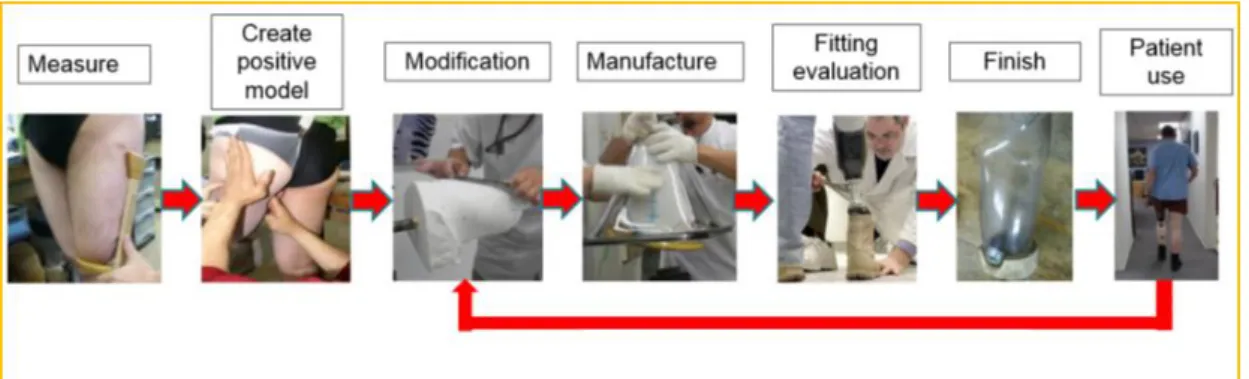
In a prosthetic device fabricator views especially prosthetic socket fabricator, the amputee quantity increment gave them an opportunity to expand their fabrication scale. Every amputee is most likely needing a prosthetic device to support their daily life activities. However, the allocated time to produce such device is long due to various of process of evaluation before it being fabricate. Figure 1.9 showed the conventional method to fabricate the prosthetic socket.
Figure 1.9 Conventional prosthetic socket fabrication
The human resource and socket fabrication issues are a primary matter that need to be solve. Many researches have been conducted to solve the matter. An alternative method to fabricate the prosthetic socket has be introduced by utilizing a three-dimensional (3D) printing method and the method still has many evaluations needs to be conducted before it can be use.
14 comfortability, socket fitting with the residuum and the stability of the patient during wearing the socket.
In details, the post-evaluation divided by three prime evaluation which are I. Socket Fitting Evaluation
II. Dynamic of Knee Joint Evaluation
III. Stability evaluation based on ground reaction force (GRF)
Socket fitting evaluation is conducted to measure the skin-to-socket contact. When a socket is not a snug fit, the resulting gap allows the residuum to move more than it should; and the result is often sores, blisters, and ongoing pain. Experienced prosthetic practitioners know that fitting well distributes the weight and pressure evenly over areas of the residual limb that can tolerate regular pressure. Evidence shows that a good fit can also help ease phantom pain. Sometimes prostheses that cause pain or discomfort are too tight. When the socket is too constrictive, it can inhibit circulation and cause swelling or friction that results in skin abrasions. Problems with how well prostheses fit can be related to fluctuations in body weight. If you gain or lose weight, it can have an impact on the fit of your prosthesis.
The dynamic knee joint evaluation is conducted to make patient walking gait nearly similar or similar with normal walking gait. Prosthetic knee designers have used components such as springs and dampers and optimized them with an aim of replicating ideal knee moment required for walking with able-bodied kinematics [25]. However, many challenges to design and choose a good knee joint prosthesis because it depends on individual patient features, finance ability and using purpose. The understand of knee joint operation and load appeared are important parameters for design and improve quality of knee joint. Nowadays, many studies continuing finds the solution for study the quality of knee joint by using advanced technologies.
15
1.3.3 Transfemoral Prosthesis Research Difficulty
Amputation at the transfemoral level can be very challenging for the amputee as well for the surgeon, the prosthetist, the physical therapist, and every member of the health care team. In the United States, this amputation level is most commonly known as an above-knee amputation, or AKA, whereas elsewhere it is referred to as a transfemoral amputation because the amputation occurs in the thigh, through the femur. The term transfemoral amputation is gaining favour in the United States because it more accurately describes the amputation level involved. Many of the same issues are faced by amputees with knee disarticulations. Except where noted, the information provided in this monograph applies to both transfemoral amputations and knee disarticulations. Transfemoral amputations are performed less often than in the past because of new understandings of the importance of preserving the knee joint. As recently as 30 years ago, transfemoral amputations were performed frequently in patients with foot infections that required amputation. At that time, the impact of amputation level on rehabilitation and function was not fully understood. Also, the prevailing belief was that a thigh-level amputation was significantly more likely to heal than an amputation at the calf (called a transtibial amputation) or foot because amputations in the calf and foot had very poor healing rates. Thanks to better amputation surgical technique, vascular reconstruction, patient selection, and improved antibiotic treatment, amputations at the calf and foot now have an excellent chance of resulting in a well healed, functional limb.
Despite the current emphasis on performing amputations that preserve limb length, many transfemoral amputations are still required. Of the more than 1.2 million people in the United States living with limb loss, 18.5% are transfemoral amputees, according to the latest figures provided by the National Centre for Health Statistics. Dillingham and associates reported that 266,465 transfemoral amputations were performed in the United States between 1988 and 1996 (the most recent years available), an average of 29,607 annually.
16 Learning to walk after a transfemoral amputation is many times harder than learning to walk after a transtibial amputation. The transfemoral amputee not only has to learn to use a prosthetic knee but also must learn to coordinate the interaction of the foot componentry with the prosthetic knee, which requires more mental energy. In addition, achieving a comfortable socket fit is more challenging. Skills such as coming to a stand, standing balance, ambulation, and negotiating hills, stairs, and uneven terrain are more difficult. The transfemoral amputee has more difficulty with balance and decreased proprioception and therefore has both a greater risk and greater fear of falling. For these reasons, the rehabilitation process is much more difficult for the transfemoral amputee than for the transtibial amputee. Physical therapy is more prolonged (usually at least twice as long as for the transtibial amputee), and a better understanding of prosthetic components is required on the part of the physical therapist.
For the transfemoral amputee to achieve the best possible outcome, it is necessary for the physical therapist to understand the prosthetic components and how they work. The physical therapist must also know how to train the patient to function in all mobility situations and must also be familiar with issues that are relevant specifically to amputees, such as phantom pain, residual limb skin issues, and the importance of the trained peer visitor.
Physical therapists generally receive little formal training specific to working with amputees, and once in practice, most physical therapists may see one amputee a year, if that. In addition, prostheses continually change as new components become available. For many therapists, keeping up with the constantly changing world of prosthetic components is the most challenging aspect of working with amputees, especially if the basic mechanics of the prostheses are not understood. The purpose of this monograph is to provide a resource of the basic medical and prosthetic issues involved in transfemoral amputation so that with this understanding, the physical therapist is better able to treat the transfemoral amputee in such a way that a positive experience results for both the amputee and the therapist.
1.4 Research Objectives
17 ▪ Developing the three-dimensional (3D) model of residuum with precise parameter of actual residuum where the model consists of multi-material properties includes: skin, fat, muscle and bone.
▪ Designing a simulation mimicking an actual donning process to improve the evaluation fitting of transfemoral prosthesis socket in stance phase of gait.
▪ Developing an evaluation system for transfemoral prosthetic socket for the socket model created using Magnetic resonant imaging (MRI) data. The utilization of finite element method (FEM) is a primary method to achieve the objectives. The research is expected to create an overall evaluation system for the transfemoral prosthetic device especially the socket and helping the prosthetist develop biologically realistic lower-limb assistive devices that improve amputee locomotion. Furthermore, the results of the study can aid the prosthesis designer in the design of the prosthesis parts and the structure of the artificial leg, and in material selection.
By achieving the objective, fat distribution inside the transfemoral residual limb can be analyse. The fat distribution pattern and composition can be confirmed by comparing the 3D model with MRI data collected from specific subjects. The overall analysis considers as a novelty of this research because its include analysis of fat distribution analysis, fat composition behaviour of residual limb before and after inserting into prosthetic socket, pressure distribution during inserting into socket and walking phase that so far not been done in the biomedical field.
1.5 Structure of the dissertation
This dissertation is composed of six chapters.
Chapter 1 provides an outline of the whole work. The background study will be elaborate in this chapter. The introduction of transfemoral prosthesis, finite element method and the relationship between proposed study with the real-world activity will be elaborated. The objective, scope of study, limitation of the study also will be clarified in this chapter.
18 Chapter 3 present an evaluation towards 3D reconstructed model of residuum. This chapter explain the important of the model accuracy towards providing an alternative method replacing the actual human experiment. The accuracy of the model will be evaluated based on the relationship between number of intersections point during constructing the model and the volumetric value of the model.
Chapter 4 present the evaluation on the effect of prosthetic socket changes towards residuum. The study focusing on evaluating two type of prosthetic socket. The geometrical shape of residuum and the socket consider to be differed to enhance the contact surface between both of it. The geometrical changes were observed during complete stage of donning simulation. The evaluation result is an important key toward improving an accuracy of the model design.
Chapter 5 chapter presents a pressure distribution analysis occurred in prosthetic socket. The pressure measured in donning process simulation and gait cycle simulation. The 3D model created in the simulation were MRI based. The models were pre-determined with dynamic parameter that based on previous study. The result then compared with actual experiment data conducted from previous study. The result showed high correlation between simulation and experiment measurement.
Chapter 6 will conclude the study about the transfemoral prosthesis function analysis using finite element method. The achievements and the limitation of this research was explained briefly. Furthermore, some solution to improve of this work was discussed.
19
1.6 Scope of Study
In this research, several scopes of study are required to enhance the result of the research. The scope of study is divided by three main parts which are subjects, methodology and experiment procedures.
The research was conducted by utilize a three subject`s data. The quantity of the subject is small and not enough for a statistical analysis. However, there are several types of experiment was conducted using the same subject. The cumulative number of the experiment with the same subject ensure the comparison with simulation resulting a good correlation with experiment and simulation
In this research, the cloud of MRI data was used. In order to get the data of subject wearing the transfemoral prosthetic leg, subject need to lying on the bed inside the magnetic resonant device. Same procedure also applied to the subject in without prosthetic leg condition. The condition has set to ensure the quality of collected data fulfil the requirement. By this condition, the geometry of the residuum during standing position is can not be replicated. The limitation has affected the process of creating a 3D model because the model was created based on the MRI data`s specification. Therefore, in this research, we analyse the structure of residuum during inserted into the socket and compare it with result of donning simulation. The comparison can be one of the methods to justify the limitation of the taken MRI data.
In this research, MRI data was taken into consideration since it provides more level of distinguish between internal soft tissue of the residuum. In addition, the MRI image provide less harm compare to CT scan. Furthermore, the MRI data was not undergoing any filtration process to ensure the novelty of the methodology. Without the filtration, the data still provides distinguish between soft tissue such as fat, muscle and bone. With this distinction, the 3D model can be created with different internal part included.
20
Chapter 2
Literature and Technical Review
In this chapter, a relationship with the past study will be explained. This chapter will review a technical study of finite element analysis (FEA) that act as a fundamental of the overall study. Also, the basic concept of creating the precise 3D model of residuum and prosthetic socket will be highlighted. This chapter also presents a revision of the previous studies. Some prevailing results of studies are also introduced to clarify the novelty of the contributions in this work.
2.1 Technical Review
2.1.1
B-Spline interpolation
B-spline is an acronym for basic spline which can be define as a curve line drew from one point to another point. B-spline have usually been used in designing various type of model based on the location of the point. A natural way to construct a curve from a set of given points is to force the curve to pass through the points or interpolate the points. There are various type of B-spline interpolation and the study has adopted the Bezier curve interpolation method as a basic algorithm for the three-dimensional (3D) model construction process. 2.1.1.1 Bezier Curve Interpolation
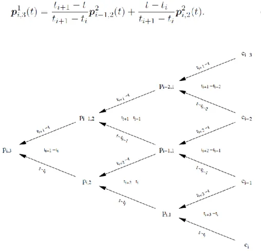
21 neighbouring pieces was depended or controlled by the chosen control points. It turns out that by adjusting the construction of Bezier curves slightly, the production pieces of polynomial curves that automatically tie together become smooth. Here the Bezier curve interpolation or spline curve can be described with below equation: 𝑝(t|𝑐1, 𝑐2; 𝑡2, 𝑡3) = 𝑡3− 𝑡 𝑡3− 𝑡2 𝑐1+ 𝑡 − 𝑡2 𝑡3− 𝑡2 𝑐2, 𝑡 ∈ [𝑡2, 𝑡3] (2.1)
where t and c denote as knot vector and control point respectively. By the setting t2<t3 and when t3=1 and t2=0, the curve equation become linear Bezier curve. The
combination of multiple active point will be creating the piecewise linear curve f and described in equation 2.2.
𝒇(𝑡) = { 𝒑(t|𝑐1, 𝑐2; 𝑡2, 𝑡3), 𝑡 ∈ [𝑡2, 𝑡3] 𝒑(t|𝑐2, 𝑐3; 𝑡3, 𝑡4), 𝑡 ∈ [𝑡3, 𝑡4] . 𝒑(t|𝑐𝑛−1, 𝑐𝑛; 𝑡𝑛, 𝑡𝑛+1), 𝑡 ∈ [𝑡𝑛, 𝑡𝑛+1] (2.2) The construction of spline curves can be generalized to arbitrary polynomial degrees by forming more averages. A cubic spline segment requires four control points ci-3, c i-2, c i-1, ci, and six knots (𝑡𝑗)
𝑗=𝑖−2 𝑖+3
which must form a nondecreasing sequence of numbers with ti < ti+1. The curve is the average of two quadratic
segments, 𝒑(t|𝑐𝑖−3, 𝑐𝑖−2, 𝑐𝑖−1, 𝑐𝑖; 𝑡𝑖−1, 𝑡𝑖−2, 𝑡𝑖, 𝑡𝑖+1, 𝑡𝑖+2, 𝑡𝑖+3) = 𝑡𝑖+1− 𝑡 𝑡𝑖+1− 𝑡𝑖 𝑝(𝑡|𝑐𝑖−3, 𝑐𝑖−2, 𝑐𝑖−1; 𝑡𝑖−1, 𝑡𝑖−2, 𝑡𝑖, 𝑡𝑖+1, 𝑡𝑖+2) + 𝑡 − 𝑡𝑖 𝑡𝑖+1− 𝑡𝑖 𝑝(𝑡|𝑐𝑖−2, 𝑐𝑖−1, 𝑐𝑖; 𝑡𝑖−1, 𝑡𝑖, 𝑡𝑖+2, 𝑡𝑖+3) (2.3)
with t varying in [ti, ti+1]. The two quadratic segments are given by convex
combinations of linear segments on the two intervals [ti−1, ti+1] and [ti, ti+2]. The
three-line segments are in turn given by convex combinations of the given points on the intervals [ti−2, ti+1], [ti−1, ti+2] and [ti, ti+3]. Note that all these intervals contain
[ti, ti+1] so that when t varies in [ti, ti+1] all the combinations involved in the
construction of the cubic curve will be convex. This also shows that we can never get division by zero since we have assumed that ti < ti+1. The generalization of the
spline curves of even higher degrees can be describe in equation 2.4.
22 polynomial degree, and the superscript s gives the gap between the knots in the computation of the weight (t − ti)/(ti+s − ti). With the abbreviation (2.4), equation
(2.3) becomes:
(2.5)
Figure 2.1 Computing a point on a cubic spline curve
The complete computations involved in computing a point on the cubic segment pi,3(t) can be arranged in the triangular array shown in Figure 2.1 (all
arguments to the pi,k have been omitted to conserve space). A segment of a
general spline curve of degree d requires d + 1 control points (𝑐𝑗)𝑗=𝑖−𝑑𝑖 and 2d
knots (𝑡𝑗)𝑗=𝑖−𝑑+1𝑖+𝑑 that form a nondecreasing sequence with ti < ti+1. The curve is a
weighted average of two curves of degree d − 1,
(2.6) Because of the assumption ti < ti+1 we never get division by zero in (2.6). The two
23 (2.7) and again, the condition ti < ti+1 saves us from dividing by zero. At the lowest level
we have d line segments that are determined directly from the control points,
(2.8) for j = i − d + 1, . . ., i. The denominators in this case are ti+1 − ti−d+1, . . ., ti+d − ti, all of
which are positive since the knots are nondecreasing with ti < ti+1. As long as t is
restricted to the interval [ti, ti+1], all the operations involved in computing pi,d(t)
are convex combinations. The complete computerization is described below equation:
(2.9) for j = i − d + r, . . ., i and r = 1, 2, . . ., d.
A spline curve of degree d with n control points (𝑐𝑖)𝑖=1𝑛 and knots (𝑡𝑖)𝑖=2𝑛+𝑑 is
given by
(2.10)
whereas before it is assumed that the knots are nondecreasing and in addition that ti < ti+1 for i = d + 1, . . ., n. Again, we can express f in terms of the piecewise
constant functions given
24
2.1.2
Finite Element Method
Finite element method (FEM) or finite element analysis (FEA) can be define as a numerical method for solving problem of engineering and mathematical physics. FEM has been utilized widely in engineering field especially in aeronautical engineering because one of its essential characteristics is the decomposition of a continuous domain into a set of discrete sub-domains. Such a characteristic provides a great advantage to employ local information comprehensively and to describe variation details, while much computation is needed.
The development of finite element methods for the solution of practical engineering problems began with the advent of the digital computer. That is, the essence of a finite element solution of an engineering problem is that a set of governing algebraic equations is established and solved, and it was only through the use of the digital computer that this process could be rendered effective and given general applicability. These two properties effectiveness and general applicability in engineering analysis-are inherent in the theory used and have been developed to a high degree for practical computations, so that finite element methods have found wide appeal in engineering practice.
In the study FEM has been utilized to create an environment where the connection between actual experiment and simulation can be realize. It is because mathematically, the finite element method is employed to find approximate solutions of partial differential equations as well as solutions of integral equations or their combinations. The solution approach is usually a numerically based simulation. However, the finite element simulation computational time are greatly affected by quantity of nodes and elements. This is because the symmetrical, banded stiffness matrix, which is a bandwidth is dependent on the difference in the node numbers for each element and this bandwidth is directly connected with the number of calculations the computer has to do.
25 The mathematical model of finite element is depending on various parameter. It included the geometry of the model, kinematic, material properties, material law, loading, boundary condition etc. Based on those parameter, numerical analysis will be conduct where it has been embedded inside the finite element simulation. In other hand, the finite element environment which is calculated based on the mathematical model is the solution that affected by the selection of certain parameter inside the model such as finite element quantity, mesh density, displacement, velocity, energy consumption, force etc. Based on the mathematical model and the environment, assessment of accuracy of finite element solution will be conducted. The feedback from the assessment will be used to refine the parameter such as mesh density etc. for creating an accurate simulation.
2.1.2.2 Nonlinear Analysis in Finite Element Method
In the research, a large deformation is hypothetically assumed happen in elastic material model. The linear elastic equation is not corresponded to the large deformation. When the problem came out of linearity of the equation such as the displacement of node is constantly changed or the force given to the model is unpredictable, the nonlinear analysis is required.
The linearity of a response prediction rests on the assumptions just stated, and it is instructive to identify in detail where these assumptions have entered the equilibrium equations in (2.12).
𝐊𝐔 = 𝐑 (2.12)
The fact that the displacements must be small has entered the evaluation of the matrix K and load vector R because all integrations have been performed over the original volume of the finite elements, and the strain-displacement matrix B of each element was assumed to be constant and independent of the element displacements. The assumption of a linear elastic material is implied in the use of a constant stress-strain matrix C, and, finally, the assumption that the boundary conditions remain unchanged is reflected in the use of constant constraint relations for the complete response. If during loading a displacement boundary condition should change, e.g., a degree of freedom which was free becomes restrained at a certain load level, the response is linear only prior to the change in boundary condition.
26 that in a materially-nonlinear analysis, the nonlinear effects lie only in the non-linear stress-strain relation.
Table 2.1 Classification of nonlinear analysis [26]
Type of Analysis Description Typical
formulation used
Stress and strain measures
Materially-nonlinear-only
Infinitesimal displacement and strains; the stress-strain relation is nonlinear Material-nonlinear-only (MNO) Engineering stress and strain
Large
displacement, large rotations, but small strains
Displacement and rotation of fibres are large, but fibres extensions and angle
changes between fibres are small; the stress-strain relation may be linear or nonlinear Total Lagrange (TL) Updated Lagrange (UL) Second Piola-Kirchhoff stress, Green-LaGrange strain Cauchy stress, Almansi strain Large displacement, large rotations, and large strains
Fibres extensions and angle
changes between fibres are large, fibre
27 (a)
(b)
(c)
Figure 2.2 illustration of nonlinear analysis types. (a) Materially-nonlinear-only (infinitesimal displacements, but nonlinear stress-strain relation); (b) Large displacements and large rotations but small strains. Linear or nonlinear material
behaviour; (c) Large displacements, large rotations, and large strains. Linear or nonlinear material behaviour [26]
28 function in the software. The settings will dictate which formulation will be used to describe the actual physical situation. Conversely, we may say that by the use of a specific formulation, a model of the actual physical situation is assumed, and the choice of formulation is part of the complete modelling process. Surely, the use of the most general large strain formulation "will always be correct"; however, the use of a more restrictive formulation may be computationally more effective and may also provide more insight into the response prediction.
2.1.2.3 Finite Element Analysis Stage
Generally, a finite element analysis (FEA) consist of three separated stages namely pre-processing, processing and postprocessing. A complete analysis is a logical interaction of these three stages.
I. Pre-processing
As the name indicates, pre-processing is something you do before processing your analysis. The pre-processing involves the preparations of data, such as nodal coordinates, connectivity, boundary conditions and loading and material information.
The preparation of data requires considerable effort if all data are to be handled manually. If the model is small, the user can often just write a text file and feed it into the processor, but as the complexity of the model grows and the number of elements increase, writing the data manually can be very time consuming and error-prone. Its therefore necessary with a computer pre-processor which help with mesh plotting and boundary conditions plotting.
For an example of a simple pre-processor, see the Java-applet on these pages. Her you can change loads, boundary conditions, mesh and element properties and material. All this is done graphically to minimize the chance of error. The only limitation is that you cannot draw your own geometry, you have to select one of the pre-generated geometries.
II. Processing
29 Figure 2.3 FEA Pre-processing (simplan.de)
III. Postprocessing
The postprocessing stage deals with the representation of results. Typically, the deformed configuration, mode shapes, temperature, and stress distribution are computed and displayed at this stage.
For an example of a simple postprocessor, see the Java applet on these pages. Here you can, after analysis of a model, view the deformed model, and inspect stresses and displacements, both in the centroid of elements and the nodal values, and see contour plotting of these data.
Figure 2.4 FEA postprocessing (simplan.de)
2.1.3
Computer Aided Drawing Software (CREO
Parametric)
30 It provides the broadest range of powerful yet flexible 3D CAD capabilities to accelerate the design of parts and assemblies.
Creo Parametric capable to create a 3D solid modelling with a precise geometry, regardless of model complexity. The technical surfacing method embedded in the software enable the user to develop a complex surface geometry with a single button click. There is a lot of `friendly` function in the software such as sweeps, blends, extends, offsets and many more to help the user creating a precise surface of a 3D model.
Figure 2.5 Creo Parametric environment and GUI (PTC Ltd.)
31
2.1.4 LS-DYNA 3D Solver
LS-Dyna is advanced general-purpose multi-physics simulation software developed by Livermore Software Technology Corporation. LS-Dyna is a Non-linear Explicit Transient Dynamic FE code, originated from the 3-D FEA program DYNA-3D developed by Dr.John.O.Hallquist at Lawrence Livermore National Laboratory, California in 1976.
The main application areas of LS-DYNA are crash simulations, metal forming simulations and the simulation of impact problems and other strongly non-linear tasks. LS-DYNA can also be used to successfully solve complex nonlinear static problems in cases where implicit solution methods cannot be applied due to con- vergence problems.
In conjunction of the variation of parameter embedded for dynamic analysis, the software was chosen to accomplish the objective of the study. LS-DYNA has embedded with encrypted keyword file namely K file to realize the simulation. K file consist of variety of keyword parameter that’s define the simulation framework. Here, the discussion of utilized keyword that contribute to the research framework will be elaborated.
2.1.4.1 Prescribed Motion
32 Figure 2.6 GUI of LS-Prepost (LS-DYNA) solver (Lstc.com)
2.1.4.2 Constraint
The constraint keyword provides a way of constraining degrees of freedom to move together in some way [27]. The keyword was used to define the constraint between a rigid body and non-rigid body. By this keyword, the non-rigid body will convert into a rigid body that posses a similar characteristic with attached rigid body. Extra nodes for rigid bodies may be placed anywhere, even outside the body, and they are assumed to be part of the rigid body. They have many uses including:
1. The definition of draw beads in metal forming applications by listing nodes along the draw bead.
2. Placing nodes where joints will be attached between rigid bodies.
3. Defining a node where point loads are to be applied or where springs may be attached.
4. Defining a lumped mass at a particular location. 2.1.4.3 Contact Definition
33 calculation equation and contact penalty value. Combining all the defined parameter, a smooth interaction between two or more model can be develop. The simulation will stop processing if the contact definition is not well tuned.
2.1.4.4 Loading Definition
The keyword *DEFINE provides a way of defining boxes, coordinate systems, load curves, tables, and orientation vectors for various uses. A definition of a curve [for example, load (ordinate value) versus time (abscissa value)], often referred to as a load curve. Curves are discretized internally with equal intervals along the abscissa for fast evaluation in constitutive models. Discretized curves are not used for evaluating loading conditions, e.g., pressures, concentrated forces, displacement boundary conditions, etc. [27].
2.2 Literature Review
2.2.1
Accuracy of 3D modelling
In this study, the accuracy of every created models is a precious benchmark towards achieving the ultimate research objective. Many studies have indicated that the accuracy of 3D model is defined by a method of creating the model.
Recent technological development has improved the method of creating a 3D model. For instance, in bio-mechanical engineering field, the utilization of machines and software, e.g Rodin 4D (Rodin 4D), CanfitTM (Vorum) and 3D
Scanner has created an accurate 3D model with the complexity of the surface structure took into consideration. These technologies help manufacturer and therapist to develop a dummy model based on actual subject measurement. However, these technologies are quite complex and involves considerable workload, besides being difficult to apply in practice due to their unclear methodologies.
34 In other studies, conducted by Giorgio Colombo et al. [29] where the construction of an amputee digital model using LifeMODTM has been reported.
LifeMODTM is a biomechanical simulation package based on MSC ADAMS solver.
The simulator is expensive and is not affordable for general users. The accuracy of created model was high due to it precision on calculating the residuum surface based on 3D scanner specification. To initialize the simulator, user need to have a lot of consideration such as financial stability etc. because the simulator is a very sophisticated and expensive to purchase. For this research, alternative method will be introduced to cover the financial problem. The method will be discussed detail in chapter 3.
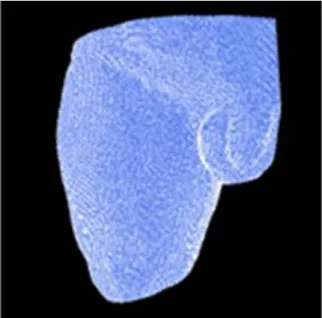
Arun Dayal Udai and Amarendra Nath Sinha [30] reported the use of a combination of CAD and image processing tools to generate an accurate 3D model. The usage of MATLAB for filtering the Magnetic Resonance Imaging (MRI) image is necessary to determine the outer geometry of the image before it was used to construct the model. By the filtering technique, the accuracy of 3D model can be enhanced. The filtering technique also can be use not only in MRI image, but it also can be use in CT image and RGB image as usual. However, in their paper, the accuracies of the model’s volume, shape, and composition of fat, skin, muscle, and bone were not evaluated. The accuracy of the 3D model is discussed by comparing the residuum model structure with outer geometry of the MRI image. In conjunction of the matter, this study has proposed a novel methodology to evaluate the accuracy of the 3D model.
2.2.2 Transfemoral Prostheses Socket Function
A lower-limb prosthesis is an artificial limb that is designed to mimic the natural function, structure, and aesthetics of a limb that is replaced. Different types of lower-limb prosthesis exist based on the levels of extremity of the lower-limb amputations. A transfemoral or above-knee prosthesis is an artificial limb for a case in which the knee joint is removed, and part of the femur or thigh bone remains intact. The socket is one of the most important parts of the transfemoral prosthesis because it acts as a connection between the residual limb and prosthesis. It protects the residual limb and appropriately transfers forces during standing and ambulation motions.
35 of their product or rehabilitation method. Most of the research focused on the surface pressure analysis of socket at certain point. Few studies focusing on trans-tibial or below-knee prosthesis utilized the finite element method to determine the stress distribution [32-33]. However, the measured change of volume in soft tissue was very low since the shape of residuum and socket were assumed to be the same.
Reference [31] used five sample subject data to perform the actual donning procedure. However, due to the similarity of the socket and residuum shape, the maximum contact pressure observed in the study (5.6 kPa) was lower than other studies. Reference [34] utilized a non-linear FE model with a homogenous and isotropic residuum contacted with socket. 80.57 kPa of maximum normal stress recorded at the distal end of the residuum. Their result difference from other in term of maximum stress on the residuum probably because the shape of the rectified socket was assumed to be the same as residuum. There are case studies on the behaviour of residuum [35-36], which characterized the mechanical condition of muscle flap of a trans-tibial patient for static load bearing. Here, the residuum model was divided into three parts viz., bone, muscle, and skin. The simulation revealed that the interface pressure between residuum and socket was 65 kPa, which has high correlation with the pressure obtained in clinical measurement.
2.2.3 Pressure Distribution in Prostheses Socket
The skin and soft tissue of a residual limb are subject to stress and excessive distortion during gait positioning [37] and are significantly higher during transfemoral prosthesis since a residual limb is comprised of complex soft tissue and experiences a large change in volume with the use of sockets. Thus, the prosthesis is unstable, and this makes it difficult for the patient. In order to evaluate the quality of socket design and fit, the pressure distribution at the interface between the residual limb and prosthetic socket is considered as an extremely important factor. An abnormal force transferred from the socket to a residual limb can cause unstable gait, pressure ulcers, and deep tissue injuries.
36 Besides focusing on socket design and manufacturing methods, Sengeh et. al [42] was determined to investigate the effect of designing residuum model with multi-material towards an accuracy of actual residuum parameter. The residuum was modelled with subject-specific magnetic resonant (MR) image to allow the model being evaluated with numerical approach and its inspired this study to model the residuum with subject-specific parameter but with different methodology. Portnoy et. al [43] also reported that using subject-specific analysis of internal tissue loads in the residuum in real time is a practical tool for evaluating an internal stress inside residuum in clinical setting or outdoors.
![Figure 1.8 Straight (left) and bent (right) images of the hydraulic prosthetic knee joint are seen [23]](https://thumb-ap.123doks.com/thumbv2/123deta/9765950.1849954/28.892.254.636.581.910/figure-straight-left-right-images-hydraulic-prosthetic-joint.webp)

![Figure 3.3 Completed Residual surface by Arun Dayal et. al [30].](https://thumb-ap.123doks.com/thumbv2/123deta/9765950.1849954/56.892.230.659.148.421/figure-completed-residual-surface-arun-dayal-et-al.webp)