PAPER
Characteristics and Applicability of Frequency Sharing Criteria in the Broadcasting Satellite Link
Kazuyoshi SHOGEN†a),Fellow andThong PHAM VIET††,Nonmember
SUMMARY Two frequency sharing criteria for BSS (Broadcasting- Satellite Service) are enacted in Sect. 1 of Annex 1 to Appendix 30 to Ra- dio Regulations. These two criteria are pfd (power flux-density) and EPM (Equivalent Protection Margin) values. In this paper, the two criteria are compared and studied from the view point of applicability to the sharing cases between BSS and BSS. In particular, it is shown that in some cases, the EPM criterion contributes to alleviate the problem of “sensitive satellite network”, i.e., one that has relatively low transmission power and is very weak against interference and blocks the new satellite to enter.
DisclaimerThe views and positions expressed by the authors are strictly personal and do not constitute, nor can be interpreted as, the position of the International Telecommunication Union on the topics addressed in this paper.
key words: broadcasting-satellite service, frequency sharing criteria, equivalent protection margin, power flux-density
1. Introduction
This paper describes the two frequency sharing criteria be- tween BSS (Broadcasting-Satellite Service) networks. In Section 1 of Annex 1 to Appendix 30 to RR (Radio Regula- tions), two types of threshold value triggering coordination are given: a) pfd (power flux-density) and b) EPM (Equiva- lent Protection Margin). According to the provision in RR as cited below[1], a proposed satellite network does not need to coordinate with others if either the pfd criterion or the EPM criterion is met.
.., an administration in Region 1 or 3 is considered as not being affected if either of the following two conditions is met:
a) .., the power flux-density at any test point within the ser- vice area .., does not exceed the following values: (WRC-15) . . .
b) . . . the equivalent downlink protection margin corre- sponding to a test point of its assignment . . . does not fall more than 0.45 dB below 0 dB or, if already negative, more than 0.45 dB.
For the allocation of frequencies the world has been divided into three Regions. Region 1 is Europe including countries belonging to the former Soviet Union and Africa; Region 2 is America and Region 3 is Asia and Oceania. The pfd
Manuscript received January 27, 2019.
Manuscript revised April 18, 2019.
Manuscript publicized June 17, 2019.
†The author is with B-SAT, Tokyo, 157-0063 Japan.
††The author is with Radiocommunication Bureau, ITU-R, CH- 1211, Geneva 20, Switzerland.
a) E-mail: [email protected]
DOI: 10.1587/transcom.2019EBP3023
criterion was introduced in addition to the EPM criterion by WRC-2000 (World Radiocommunication Conference in 2000) for BSS only in Region 1 and Region 3, but not for BSS in Region 2. In Regions 1 and 3, since a new satellite only needs to meet one of the two criteria, it is easier for the new satellite to be successfully coordinated than in case of Region 2. In this paper, the comparison between the two cri- teria and their characteristics are studied thus focusing only on Regions 1 and 3.
This study is useful for satellite broadcasting system designs including the selection of an orbital position, in which the possible impact of interference on the BSS satel- lite networks can be taken into account. Concerning the se- lection of an orbital position, this study also explains which criterion should be used by a proposed new network so that the proposed new network can transmit higher power and at the same time other BSS networks will not be considered as being affected by the proposed new network.
From the aspect of regulations, it was not clear about the features and merits of the two criteria. In this paper the consideration is given, and in particular it is shown that the EPM criterion contributes to alleviate the problem of “sen- sitive satellite network”, that has a low transmitting power and is very weak against interference, then results in the ir- rational blockage to a new comer. It means the EPM cri- terion contributes to the efficient use of orbit/spectrum re- sources. Examples of such “sensitive satellite networks”
can be found in BR-IFIC (Space services) (Radiocommuni- cation Bureau - International Frequency Information Circu- lar) data issued by ITU-R (International Telecommunication Union – Radiocommunication Sector). The mechanism for the alleviation of such a problem is explained.
2. Pfd Criterion
This section explains the pfd criterion and its features. The pfd value is derived as e.i.r.p. (Equivalent Isotropically Ra- diated Power) divided by 4∗π∗d2, wheredis the distance between the satellite and the receiving point on the Earth where the pfd value will be calculated. The pfd criterion is easy to be calculated and understood. Therefore, it was proposed in WRC-2000 to suppress the EPM criterion and only the pfd criterion was introduced for the BSS and BSS sharing in Regions 1 and 3.
The threshold pfd value triggering coordination is shown below in italics (cited from RR [1]), as a function of orbital separation angleθbetween two BSS satellites.
Copyright c2019 The Institute of Electronics, Information and Communication Engineers
−147 dB(W/(m2·27 MHz)) for 0◦≤θ <0.23◦
−135.7+17.74 log(θ) dB(W/(m2·27 MHz)) for 0.23◦≤θ <
2.0◦
−136.7+1.66θ2dB(W/(m2·27 MHz)) for 2.0◦≤θ <3.59◦
−129.2+25 log(θ) dB(W/(m2·27 MHz)) for 3.59◦≤θ <9.0◦ (1) whereθis the minimum geocentric orbital separation in de- grees between the wanted and interfering space stations, taking into account the respective East-West station-keeping accuracies.
Regarding the satellite station-keeping above, RR requires that space stations in BSS must be maintained in position with an accuracy equal to or better than+/−0.1 degrees in the East - West directions.
The threshold pfd value above is depicted in Fig. 1 (WRC-2003, Blue line). Note that the pfd value in Fig. 1 is expressed per 1 MHz bandwidth, instead of 27 MHz, in or- der to be consistent with other sharing cases. The threshold pfd value is the single–entry interference level as indicated
“I” of an interfering satellite (new comer) in Fig. 1. It is an absolute value regardless of the wanted level as indicated
“C” of an interfered-with satellite (existing) in Fig. 1.
The threshold pfd value was derived based on the an- tenna discrimination of 60 cm to 2.4 m diameters. The refer- ence receiving earth station antenna pattern is given in Fig. 7 bisin Sect. 3.7.2, Annex 5 of Appendix 30 to RR. Figure 2 overwrites the pfd value (WRC-2003) with the antenna dis- crimination of 60 cm diameter. Note that the angles in the abscissa for the 60 cm antenna is transformed from a geo- centric angle to a topocentric angle under the assumption that the earth station antenna locates at a latitude of 33 de- grees North and the difference between its longitude and the satellite orbital position is 13 degrees. The location of the earth station is the same throughout this paper.
For the purpose of comparison, the threshold pfd value developed in WRC-2000[2]is also shown in Fig. 1 (WRC- 2000, Red line). The pfd value was reduced by 1.7 dB be- tween 2◦ and 9◦ (See Fig. 3) in WRC-2003 in order to re- flect the reduction of PR (Protection Ratio) by 3 dB (24 dB to 21 dB)[3]. In effect, this reduction of the threshold pfd value plays a role to protect a smaller antenna.
Since the threshold pfd value is an absolute interfer- ence power expressed in terms of pfd, it can be converted to∆T/T (the increase of noise temperature caused by the interference and the system noise temperature ratio),∆C/N (the degradation ofC/N, Carrier to Noise ratio) defined as (C/N)−(C/(N+I)), whereC/(N+I)=−10 log(10−(C/N)/10+ 10−(C/I)/10), andI/N(Interference to Noise ratio). Note that the ∆T/T, I/N and ∆C/N are equivalent and can be con- verted from one to another[4].
In the conversion of the pfd value to∆T/Tetc., the total link noise temperature of the earth station is assumed to be 174 K (Sect. 2, Annex 6, AP30). Then the system noiseNis given as follows.
Fig. 1 Comparison of WRC-2000 and WRC-2003 pfd masks in Section 1, Annex 1, AP30.
Fig. 2 Comparison of WRC-2003 pfd masks and the antenna discrimi- nation (60 cm).
Fig. 3 Difference in pfd masks by WRC-2000 and WRC-2003.
N=kT B=−228.6 (dBW/Hz/K)+10 log(174) (dBK)+ 10 log(106) (dB)=−146.2 (dBW/MHz) (2) The interference powerIto the receiver of the earth station is derived by using the antenna discrimination D(dB) and the effective antenna areaAe(m2) as follows.
I=pfd+D+10 log(Ae) (dBW/MHz) (3) The antenna efficiency is assumed to be 61.4%, which gives the absolute maximum antenna gain of 35.5 dBi at 12.1 GHz (See Fig. 7bis, Sect. 3.7.2, Annex 5, AP30). The ∆T/T,
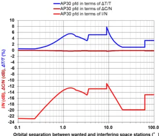
∆C/N andI/N converted from the pfd mask are shown in Fig. 4. The specific example values for 3.59◦≤θ <9.0◦are
Fig. 4 ∆T/T, ∆C/N and I/N corresponding to the pfd mask (WRC- 2003).
Table 1 Example of∆T/T,∆C/NandI/Ncorresponding to the pfd val- ues.
Fig. 5 C/Icorresponding to pfd mask (WRC-2003).
shown in Table 1.
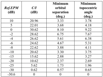
The C/I (Carrier to Interference ratio) values corre- sponding to the pfd value is a function of the wanted level (C) (See Fig. 5). The specific example values ofC/I for 3.59◦ ≤θ < 9.0◦ are shown in Table 2. Note that theC/I value corresponds to a single-entry interference.
3. EPM Criterion
This section explains the EPM criterion and its features. The
Table 2 Example ofC/Icorresponding to the pfd values.
EPM, referred to as Min this paper, is defined in Sect. 3.4 of Annex 5 to Appendix 30 to RR, as follows.
M=−10 log
10−M101 +10−M102 +10−M103
(4) whereM1is the value (dB) of the protection margin for the same channel (co-channel). This is defined in the following expression where the powers are evaluated at the receiver input:
M1 = wanted power sum of the co-channel
interfering powers (dB)
−(co-channel protection ration) (dB) (5) where co-channel protection ration is the required value of the aggregateC/Iused in the BSS Plan and is given in An- nex 5 to Appendix 30 to RR.
M2andM3are the values (dB) of the upper and lower adjacent-channel protection margins respectively.
The co-channel protection ratios (PR) in Regions 1 and 3 are as follows.
31 dB for 1977 BSS Plan.
24 dB for WRC-97 revision of BSS Plan for downlink.
21 dB for WRC-2000 digital BSS Plan.
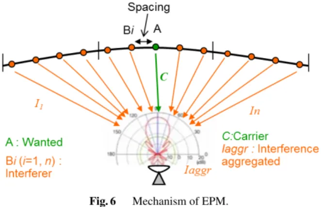
While the EPM in Eq. (4) is expressed from the view point of frequency assignments, it is expressed as the ratio of car- rier to aggregate interference by the next equation (See also Fig. 6).
M= C Iaggr
−PR= C Pn
i=1Ii
−PR (6)
A certain amount of spectrum in the BSS band is assigned equally to all countries for future use in order to guaran- tee equitable access to the geostationary orbit and spectrum among countries, which constitutes a BSS Plan. For exam- ple, in the Regions 1 and 3 BSS Plan, 12 channels in the 11.7–12.2 GHz band are assigned to all Region 3 countries.
In addition, the BSS band in Regions 1 and 3 is used through the coordination procedure and such spectrum is registered in the List, which are additional uses of satellites beyond the Plan (i.e. use of assignments with characteristics differ- ent from those appearing in the Regions 1 and 3 Plan and which are capable of causing more interference than the cor- responding entries in the Plan or use of assignments in ad- dition to those appearing in the Plan). For an assignment, Reference EPM (Ref. EPM) is defined in ITU-R to be the EPM when all the interfering assignments in the Plan and
Fig. 6 Mechanism of EPM.
Table 3 Example of the relation among transmitting power,Ref. EPM, thresholdC/Inew. etc.
the List located within 9 degrees coordination arc of that as- signment are considered. Note that theRef. EPMis updated by ITU-R every time a new assignment is entered in the Plan or the List or an assignment in the List is cancelled.
The EPM criterion is hard to be calculated and under- stood, but it considers all interference sources coming from other BSS networks. In Regions 1 and 3, according to RR, only other BSS networks located within+/−9 degrees are taken into account in calculating EPM. It is useful to recog- nize the total amount of interference in terms of aggregate interference because the BSS Plan is for future use. The EPM criterion was adopted since the development of the BSS Plan back in 1977 and in WRC-2000 the EPM crite- rion was kept despite proposals to suppress it.
The EPM criterion giving the threshold value for co- ordination is described in Sect. 1, Annex 1 of Appendix 30 to RR (See1. Introductionof this paper). Table 3 shows an example of the relation among transmitting power,Ref.
EPM, thresholdC/Inew, etc., in particular it shows how much interference is allowed for a new comer depending on theRef. EPMof an existing network so that the existing net- work is not considered as being affected by the new comer.
The colors of the numbers in Table 3 correspond to Fig. 7 and Fig. 8, respectively.
In Table 3, the items are as follows.
Ce.i.r.p. is e.i.r.p. of the wanted satellite.
Ref. EPM is the current EPM value without taking into ac- count the interference from the new comer.
C/Iaggr is the current value and derived byPR+Ref. EPM.
TheCas well asIaggrshould be, by definition, wanted and aggregate interference powers, respectively, at the
Fig. 7 EPM criterion in terms of EPM degradation.
Fig. 8 EPM criterion in terms ofC/Inew.
output of the interfered-with receiving earth station antenna. However, in this paper, C is expressed as the same as Ce.i.r.p. and Iaggr is expressed as the sum of (interfering e.i.r.p.+the discrimination (<=0) of the interfered-with receiving earth station antenna).
This expression does not change the conclusion of this study.
Iaggr is derived by Ce.i.r.p. −C/Iaggr. As mentioned above, the value ofIaggr(equivalent interfering e.i.r.p value) has been taken into account the discrimination of the interfered-with receiving earth station antenna between the wanted and the interfering satellites.
C/Inew is mathematically derived by −10 log (10−(C/(Iaggr+Inew))/10−10−(C/Iaggr)/10). However, in Ta- ble 3, it is derived so that theInewmeets the EPM cri- terion (See Fig. 8 and b) from1. Introductionas cited from RR). This is the lowestC/Inewof the existing net- work due to interference from the new comer so that the existing network is not considered as being affected by the new comer.
Inew is derived by Ce.i.r.p. −C/Inew. It indicates the maximum allowable interference power. Inewshould be, by definition, interference power at the output of interfered-with earth station antenna. However, in this
paper,Inewis expressed as the interferinge.i.r.p+the discrimination of the interfered-with receiving earth station antenna. This expression does not change the conclusion of this study.
C/(Iaggr+Inew) is the resulting value and derived by
−10 log(10−(C/Iaggr)/10 +10−(C/Inew)/10) or PR + EPM (Iaggr+Inew).
EPM(Iaggr+Inew) is the new EPM value taking into ac- count the maximum allowable interference from the new comer. According to RR, an existing network is not considered as affected by the new comer if theRef.
EPM is not degraded more than 0.45 dB below zero if the Ref. EPM value is not negative or more than 0.45 dB if theRef. EPMvalue is already negative (See Fig. 7). Thus, it is derived:
- IfRef. EPM>=0,EPM(Iaggr+Inew)=−0.45 - IfRef. EPM<0.EPM(Iaggr+Inew)=Ref. EPM
−0.45.
Degradation is the difference between Ref. EPM and EPM(Iaggr+Inew).
As same as above with the pfd criterion, it is assumed that the antenna is 60 cm in diameter, the earth station antenna locates at a latitude of 33 degrees North and the difference between its longitude and the satellite orbital position is 13 degrees.
The EPM criterion in terms of EPM degradation is de- picted in Fig. 7. It shows the resulting EPM (New EPM) when the 0.45 dB degradation principle is applied.
The EPM criterion in terms of C/Inew is shown in Fig. 8. TheC/Inewgives a threshold value, or a permissible value of the interferenceInewwhen the 0.45 dB degradation principle is applied. Note that theC/Inewis independent of the value ofCe.i.r.p.
Table 4 below indicates minimum orbital separations for a new network to co-exist with an existing network based on the EPM criterion assuming both networks have the same characteristics (60 cm diameter of receiving antenna, same transmitting power, etc.). The earth station antenna is as- sumed to locate at a latitude of 33 degrees North and the difference between the longitude and the satellite orbital po- sition is 13 degrees.
From Tables 3, 4, Fig. 7 and Fig. 8, the following items are observed.
(1) For an assignment with a high (positive)Ref. EPM, it al- lows relatively high interference caused by the new comer, while ensuring a good level of protection to the existing as- signment, up to such a level corresponding to the EPM of
−0.45 dB. For example, when theRef. EPM is 15 dB, the Inew(maximum allowable interference) is 33.6 dBW, which is higher than 23.7 dBW ofInewwhen theRef. EPMis 0 dB.
(2) For an assignment with aRef. EPMaround 0 dB, it al- lows relatively low interference to give a further degradation of EPM by −0.45 dB. Note that at 0 dB of Ref. EPM, the C/Inewis maximum andInewis minimum (23.7 dBW in Ta- ble 3), which means the assignment is most sensitive when
Table 4 Minimum orbital separation based on EPM criterion.
theRef. EPMis 0 dB.
(3) For an assignment with a very low Ref. EPMless than
−10 dB, it allows relatively high interference caused by the new comer to give a further degradation of EPM by
−0.45 dB, which means that the assignment will not be iden- tified by ITU-R as being affected if a new comer does not produce up to such a high interference. In other words, it is easier for a new comer to meet the sharing criterion. For ex- ample, when theRef. EPMis−15 dB, theInewis 38.7 dBW, which is higher than 23.7 dBW ofInewwhen theRef. EPM is 0 dB.
4. Applicability of Pfd and EPM Criteria
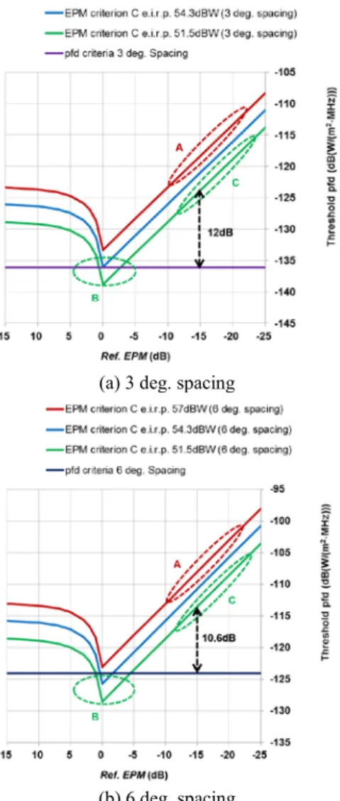
In this section, the relation and applicability of pfd and EPM criteria are investigated. In order to compare the EPM cri- terion with the pfd criterion, the EPM criterion is converted into the threshold pfd values. Figure 9 shows an example of the characteristics of Ref. EPM vs threshold pfd values for the pfd and EPM criteria in order to clarify the applica- bility of the two criteria. In other words, it clarifies which criterion should be used so that a new comer can transmit more power and at the same time does not affect an existing network.
In Fig. 9, theInewvalues in Table 3 derived under the EPM criterion are converted into the threshold pfd values at the receiving earth station.
The following explains how the conversion ofInewto threshold pfd (dB(W/(m2·MHz))) was done for a case of Ce.i.r.p. of 54.3 dBW,Ref. EPM of 0 dB and orbital sepa- ration of 3 degrees and 6 degrees.
Inewin 27 MHz: 23.7 dB(W/27MHz)
Inewin 1 MHz: 9.4 dB(W/MHz) i.e. (23.7−10 log(27)) pfd toward boresight: −153.8 dB(W/(m2·MHz)) i.e. (9.4–
162.4 (d=37187 km))
Offaxis angle of the receiving earth station antenna on the Earth (topo-centric angle toward the interfering satel- lite): 3.4 deg. for 3 deg. spacing, 6.7 deg. for 6 deg. spacing.
Discrimination of 60 cm receiving earth station antenna on
Fig. 9 Example of EPM and pfd criteria in terms of threshold pfd.
the Earth at 3.4 deg:−17 dB, at 6.7 deg.:−27 dB
pfd produced by the new comer: −136.0 dB(W/(m2·MHz)) (−153.8+17) for 3 deg. spacing,−126.0 dB(W/(m2·MHz)) (−153.8+27) for 6 deg. spacing.
It is interesting to know that, in this case, the threshold pfd value (−136.1 dB(W/(m2·MHz))) derived from the EPM criterion with 0 dB ofRef. EPM for Ce.i.r.p. of 54.3 dBW coincides to the one derived from the pfd criterion for the 3 deg. spacing between the wanted and interfering satellites.
It can be seen from Fig. 9 that in a range ofRef. EPM about from 0 dB to−5 dB, the pfd criterion is effective for lowCe.i.r.p.like 51.5 dBW.
It is also interesting to know that, when theRef. EPM is very low (less than about−10 dB to −15 dB), the EPM criterion is effective and it allows relatively high interfer- ence caused by the new comer. The BSS Plan is devel- oped generally assumingCe.i.r.p.of 59 dBW in a 27 MHz bandwidth at the peak and 56 dBW at the edge of cover- age. The assignment with a low transmitting power, e.g., Ce.i.r.p.of 51.5 dBW, is possible, but if there are Plan as- signments and/or List assignments near such a satellite with
co-coverage/co-frequency, the low power satellite suffers from high interference and results in a very lowRef. EPM (Part “C” in Fig. 9), then it can never get a value of about 0 dB ofRef. EPM(Part “B” in Fig. 9).
For example, for the Ref. EPM of −15 dB, the dif- ference between the threshold pfd’s of the EPM criterion (−124.1 dB(W/(m2·MHz))) and the pfd criterion with 3 deg.
separation (−136.1 dB(W/(m2·MHz))) is about 12 dB. The relaxation of 12 dB under the EPM criterion makes the co- ordination much easier for a new comer than under the pfd criterion. In other words, by using the EPM criterion, a new comer can transmit 12 dB more power than using the pfd cri- terion while that sensitive network is not affected. The more negative the Ref. EPM is, the larger difference between the two criteria becomes. Therefore, it can be said that the EPM criterion contributes to alleviate the problem of “sensitive satellite network”, which has a low transmitting power and permits a low interference power under the pfd criterion.
On the contrary, in Part “A” in Fig. 9, both of the interfered-with satellite and the interfering satellite have a highCe.i.r.p. In this case, the two satellites give detrimental interference to each other and suffer a very low EPM value.
This situation should be avoided since both satellite services become destructive.
5. Conclusion
In this paper, two frequency sharing criteria (pfd and EPM) for BSS in Regions 1 and 3 are compared and studied from the view point of applicability to the sharing cases between BSS and BSS, which was not clear before. This study is use- ful for satellite broadcasting system designs including the selection of an orbital position. From the aspect of regu- lations, the mechanism for the alleviation of a problem of
“sensitive satellite network” is clarified.
It was assumed in this paper that the receiving earth station antenna is 60 cm in diameter and locates at a latitude of 33 degrees North and the difference between its longitude and the satellite orbital position is 13 degrees.
The following conclusions are obtained.
(1) The threshold pfd value given by the pfd criterion is an absolute interference power. The threshold pfd value in the area of 3.59◦ ≤θ < 9.0◦(orbital separation angle) is converted and corresponds to∆T/T of 5.24%,∆C/N of−0.22 dB andI/Nof−12.81 dB, which are all equiv- alent. In the same area, the pfd value corresponds to 29 dB ofC/Ifor theCe.i.r.p.of 54.3 dB(W/27 MHz).
(2) For an assignment with a high (positive)Ref. EPM, it allows relatively high interference levels from a new comer while maintaining a high level of aggregateC/I ratio.
(3) For an assignment with aRef. EPMaround 0 dB, it al- lows relatively low interference. At 0 dB ofRef. EPM, the C/Inew is maximum therefore Inew is minimum, which means the assignment is most protective (most sensitive).
(4) For an assignment with a very lowRef. EPMless than
−10 dB, it allows relatively high interference and the assignment will not be identified by ITU-R as being affected if a new comer does not produce up to such a high interference. In other words, it is easier for a new comer to meet the sharing criteria.
(5) It is shown the applicability of the pfd and EPM crite- ria with respect to theRef. EPM. The EPM criterion is mostly dominant, and the pfd criterion is dominant in a range ofRef. EPMabout from 0 dB to−5 dB for low Ce.i.r.p.
(6) The low power satellite suffers from high interference and results in a very lowRef. EPM. The EPM criterion contributes to the alleviation of the problem of “sensi- tive satellite network”, i.e., one that has relatively low transmission power and is very weak against interfer- ence and blocks the new satellite to enter under the pfd criterion when the orbital separation is small.
The impacts of the use of the antenna size other than 60 cm and the different receiving points are left for further study.
References
[1] ITU-R, Section 1, Annex 1 of Appendix 30 to Radio Regulations, 2016.
[2] ITU-R, Section 1, Annex 1 of Appendix 30 to Radio Regulations, 2001.
[3] ITU-R, Section 3.4, Annex 5 of Appendix 30 to Radio Regulations, 2016.
[4] K. Shogen, M. Kamei, S. Nakazawa, and S. Tanaka, “Impact of in- terference on 12 GHz band broadcasting satellite services in terms of increase rate of outage time caused by rain attenuation,” IEICE Trans.
Commun., vol.E99-B, no.10, pp.2121–2127, Oct. 2016.
Kazuyoshi Shogen received the B.E., the M.E. and the D.E. degrees from the University of Tohoku, Japan, in 1977, 1979 and 1993, re- spectively. He joined NHK (Japan Broadcasting Corporation) in 1979. He has been engaged in research on broadcasting satellite system, espe- cially on contoured beam antennas for Japanese direct broadcasting satellites since 1982. From 1988 to 1989 he was a visiting scholar at the University of Illinois, Urbana-Champaign. In 1998–2003, he worked in NHK Engineering Administration Department working with groups such as the ABU (Oc- tober 1999–), ITU-R (May 1995–) and APT (December 1998–). He retired from NHK in June 2011 and he is now in B-SAT. He was the chairman of ABU Technical Committee (November 2006–October 2010) and was the vice chairman of the ITU-R SG6 WP6S (March 2002–October 2007). He is an IEEE Senior Member and a Fellow of IEICE of Japan.
Thong Pham Viet received the B.E. and the M.E. from the Hanoi University of Technol- ogy in 1997 and 2001, respectively. His ma- jor was telecommunication and he stayed in the University as a teaching assistant for 2 years af- ter his graduation. At the same time, he was em- ployed by the Vietnamese Administration from 1997 to 2008 to carry out frequency coordi- nation and studies on the feasibility and pay- load for Vietnamese first communication satel- lite project. Then he joined the ITU in Novem- ber 2008. Since then, he has worked in the Space Notification and Plans Division, which is responsible for managing the BSS and FSS Plans.