INVITED PAPER
Special Section on Electronic DisplaysGeometric Deformation Analysis of Ray-Sampling Plane Method for Projection-Type Holographic Display
Koki WAKUNAMI†a),Nonmember, Yasuyuki ICHIHASHI†, Ryutaro OI†, Makoto OKUI†,Members, Boaz Jessie JACKIN†,andKenji YAMAMOTO†,Nonmembers
SUMMARY Computer-generated hologram based on ray-sampling plane method was newly applied to the projection-type holographic dis- play that consists of the holographic projection and the holographic optical element screen. In the proposed method, geometric deformation character- istic of the holographic image via the display system was mathematically derived and canceled out by the coordinate transformation of ray-sampling condition to avoid the image distortion. In the experiment, holographic image reconstruction with the arbitral depth expression without image dis- tortion could be optically demonstrated.
key words: holography, computer-generated hologram, holographic opti- cal element
1. Introduction
Holography is a technique that has a potential to reproduce all the depth cues for three-dimensional (3D) perception of human vision. Thanks to the recent developments of the high-speed computing and the industry of high-resolution spatial light modulators (SLMs), many research groups are addressing the development of electronic-holography tech- nology[1]–[8]. However, as long as SLMs having severe limitation of spatio-temporal resolution are used in holo- gram reconstruction, we still face the inherent trade-offbe- tween the display size and the maximum diffraction angle of the controllable light. This trade-offbetween the display size and the diffraction angle has been well formulated, as the theory of the space-bandwidth product[9]. Totally, it is difficult to realize practical display design of electronic- holography by using current SLMs.
Recently we have proposed a projection-type holo- graphic display in which a holographic image reproduced by electronic-holography system is largely projected on an HOE screen[10]. On this HOE screen, a concave- mirror function was implemented as a reflection-type vol- ume hologram by wavefront printing technique[11]–[14]
to concentrate the projected light to a target observation point. Therefore, the observer can see the enlarged holo- graphic image with a large visual angle via the transpar- ent HOE screen. Note that this technique does not increase the space-bandwidth product, namely the observable area is still highly limited by the maximum diffraction angle of the holographic image on the HOE screen. However, by
Manuscript received February 28, 2018.
Manuscript revised June 4, 2018.
†The authors are with National Institute of Information and Communications Technology, Koganei-shi, 184–8795 Japan.
a) E-mail: k.wakunami@nict.go.jp DOI: 10.1587/transele.E101.C.863
the combination of any viewing angle expansion technique of holographic image[15],[16]or the multiple holographic projection from different incident directions to the HOE screen, this system will be able to extend the observable area to be used some practical applications of holographic 3D displays, such as in-car head-up displays, smart-glasses and head-mounted displays; they will permit the design of displays with a narrow observable area.
For designing of holographic display systems, how to calculate hologram data: computer-generated holograms (CGHs), striking a balance between the calculation cost and the image quality is also important topic. In Ref.[10], holo- graphic stereogram (HS)-based approach was applied to re- produce two objects set at the different depths from the HOE screen. Since HS-based approach is following a principle of light field theory[17], matured computer-graphics (CG) techniques, such as shading, lighting, occlusion culling and texture mapping, can be directly reflected on the reproduced holographic image. However, due to a ray sampling and a diffraction effect of reconstructed rays, image resolution must be decreased in the proportion of distance from a dis- play[18]–[21]. This causes a limitation of depth range of re- produced 3D image retaining the image resolution, although deep/wide depth expression of 3D image reconstruction is one important advantage of holography compared with other 3D display technologies. As a result, in Ref.[10], the optical reconstruction with only a few centimeters of depth expres- sion was demonstrated. On the other hand, point/polygon- based approaches[22],[23]have a potential to reproduce 3D image with much wider depth range by reason of strict wave propagation calculation from light sources to a hologram plane considering with diffraction effect, while a calculation cost is increased in proportion to a number of light sources.
Ray-sampling (RS) plane method is a hybrid approach of HS-based and point/polygon-based approaches[24]. In RS plane method, dense rays are once sampled in the same manner as HS-based approach but not on a display plane, on a virtual “RS plane” close to a target object in 3D space. Ray information is then converted into a wavefront on the basis of angular spectrum theory[25]at each ray sampling point, then wave propagation from RS plane to a hologram plane is calculated to simulate the object light. Even RS plane behaves as virtual HS display plane, the image degradation can be much suppressed compared with HS-based method because ray sampling is executed close to a target object and diffraction effect is considered by wave propagation Copyright c2018 The Institute of Electronics, Information and Communication Engineers
864
IEICE TRANS. ELECTRON., VOL.E101–C, NO.11 NOVEMBER 2018
calculation.
In our previous work, RS plane method was not sup- posed any wavefront deformation in display system, such as rescale by projection lens and convergence by concave mir- ror used in our projection-type holographic display. There- fore, the holographic image will get distortion in the opti- cal reconstruction if CGH is calculated by an original RS plane method. However, several practical application fields listed above must require this kind of deformation in the display system to achieve large image size retaining space- saving display design. Hence, in this paper, the refined RS plane method is newly proposed for our projection-type holographic display. In the proposed method, geometric de- formation due to the combination of projection lens and the HOE screen with concave-mirror function was mathemati- cally derived. Then the coordinate of the RS plane and di- rection of ray sampling were transformed to cancel out the image distortion. In the experiment, it was confirmed that the proposed method can reproduce several target objects set at the different depths correctly retaining the image res- olution, while a conventional HS-based method suffers the image degradation in proportion to the depth of the target object.
2. Method
2.1 Projection-Type Holographic Display
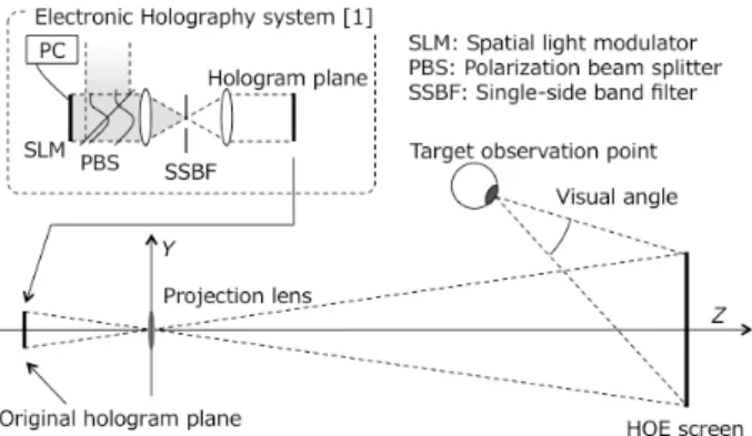
Figure 1 shows an optical setup of the projection-type holo- graphic display in this paper[10]. This system consists of a digital holographic projector and an HOE screen. CGH is displayed on 8K (7,680×4,320 pixels) liquid crystal on silicon (LCOS)-SLM. A reconstructed hologram image in which a direct light and a conjugate image are eliminated by single-side band filter, is formed around the original holo- gram plane [see Fig. 1].
An original hologram image is then largely projected through a projection lens at a reflection-type HOE screen.
This HOE screen was fabricated by wavefront printing tech- nique[14]and behaves as concave mirror to concentrate a projected light to a target observation point. Therefore, an enlarged holographic image is able to be observed with a large visual angle from a target observation point. Here
Fig. 1 A principle of projection-type holographic display in this paper.
after, the origin of coordinates is defined at the center of pro- jection lens, and the optical axis passes in the direction from the center of SLM to the HOE screen [See Fig. 1]. Because of the enlargement of a holographic image, the maximum diffraction angleθscreenat HOE screen is written as
θscreen=sin−1
λ
2MPLpSLM
, (1)
where λ is wavelength, pSLM is pixel period, and MPL is magnification ratio by projection lens. To be precise, Eq. (1) is not strictly accurate andθscreen will slightly vary in the HOE screen depending on the incident angle of the pro- jected light, but it is ignored in this paper for simplification.
Moreover,θscreen will become half actually for vertical di- rection after passing through a single-side band filter with half-zone plate processing.
Around a target observation point, a hologram image is observable from the eye-box where the all diffracted light from HOE screen are overlapping for axial and lateral di- rections [See gray color painted region in Fig. 2]. A size of eye-box for lateral direction WEB is approximately derived as
WEB=2DEBtanθscreen, (2)
whereDEBis a distance between a center of HOE screen and a target observation point.
2.2 Geometric Deformation Characteristic of Proposed Display System
A straightforward way to calculate CGH for the display dis- cussed in 2.1 is to simulate overall light propagation and deformation from SLM to a target observation point based on wave optics; however, it might take calculation time/cost.
In this paper, we geometrically analyze the deforma- tion of the holographic image by the display system. Fig- ure 3 is the detail expression of the display system shown in Fig. 1. The transformation between two spaces, (i) “the SLM space”, where the original hologram is displayed and (ii) “the HOE screen space”, where the final reconstruction is observed, is mathematically derived.
Now, the focal length of concave-mirror function im- plemented on the HOE screen is written as
Fig. 2 A relationship between a maximum diffraction angleθscreenand an eye-box sizeWEB.
Fig. 3 Geometric model of display system in Y-Z plane.
fCM= DPLDT
DPL+DT
, (3)
where DPL = ZCM − fPL is the distance between a center of holographic projection and the HOE screen, andDT = ZCM−ZT is the distance between the HOE screen and the target observation point, respectively. Moreover, a center of concave-mirror function is defined as (0,YCM,ZCM) andYCM
is derived by YCM= DPLYT
DPL+DT
. (4)
A pointP=(XP,YP,ZP), virtually set in the hologram cal- culation to be reconstructed in the SLM space, forms a real imageQ=(XQ,YQ,ZQ) in the HOE screen space through a projection lens on the basis of lens formula as
ZQ= fPL|ZP|
|ZP| −fPL
, (5)
XQ=−MPQXP, (6)
YQ=−MPQYP, (7)
whereMPQ =ZQ/ZP is lateral magnification ratio between pointsPandQ. Then a real imageQforms a virtual image R=(XR,YR,ZR) via concave-mirror function implemented on the HOE screen based on mirror formula as follows
ZR= −DQfCM
DQ−fCM
+ZCM, (8)
XR=MQRXQ, (9)
YR=YCM−MQR(YCM−YQ), (10) where DQ = ZCM−ZQ, is the distance between the HOE screen and the pointQ,DR =ZR−ZCM is the distance be- tween the HOE screen and the pointR, andMQR =DR/DQ
is lateral magnification ratio between pointsQandR. For simplification, note thatZPis supposed to satisfy the follow- ing condition to form a pointRas a “virtual image” behind the HOE screen and not a real image in front of the HOE
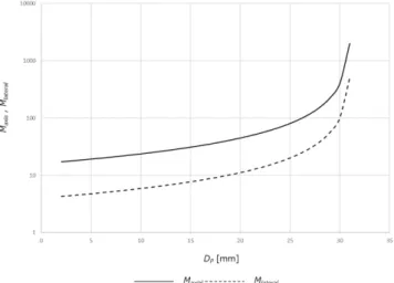
Fig. 4 A relationship between depths DPversus lateral and axial magni- fication ratiosMaxialandMlateral.
screen to the observers.
fPL(ZCM−fCM)
ZCM−fCM−fPL ≤ZP≤ZSLM. (11) Therefore, if a point Pis reproduced as a holographic im- age in the SLM space, the observer will see a virtual image R over the HOE screen via overall display system. Fig- ure 4 shows relationships of distances DP versus magni- fication ratios of overall display system for axial direction Maxial=DR/DPand lateral directionMlateral=MPQ×MQR. Due to above analysis, it is clear that the display system non- linearly deforms the original hologram image in the SLM space to the final hologram image in the HOE screen space for both directions.
2.3 Refined RS-Plane Method for Projection-Type Holo- graphic Display
In the proposed method, a target object is firstly set in the HOE screen space, then RS plane “RSPR” is set close to a
866
IEICE TRANS. ELECTRON., VOL.E101–C, NO.11 NOVEMBER 2018
target object as shown in Fig. 5. On the RSPR, dense rays directed to the eye-box area around the target observation point are sampled. Then the coordinate of RS plane “RSPP” that is a conjugate of RSPR located in the SLM space, is calculated based on the equations described in 2.2. On the RSPP, dense rays of RSPRis converted into a wavefront, and this wavefront is then propagated to SLM plane numerically in the same manner of the original RS plane method, finally, CGH can be generated. In the optical reconstruction, once CGH is displayed on SLM, RSPPwill be reproduced. Then, via the projection lens and HOE screen, RSPRis formed as a virtual image of RSPPwith dense rays of a target object without distortion to be observed from a target observation point.
The coordinates transformation from a center of RSPR
at (XR,YR,ZR) to RSPP at (XP,YP,ZP) are derived from Eqs. (5)–(10) as
ZP=− fPLZQ
ZQ−fPL
, here ZQ=− fCMDR
DR−fCM +ZCM, (12) XP=− XR
MPR
, (13)
YP=−YR−(MQR−1)YCM
MPR
, (14)
whereDR,MPR,MQRare same definitions in 2.2. Also ray sampling periodsgP andgR, on RSPPand RSPR keep the following relationship as
gP= gR
MPR
. (15)
According to (12), it is clear that RSPP forms a plane in parallel to SLM plane and a propagation between them can be calculated by 2D fast calculation algorithm based on FFT in the same manner as original RS plane method. In this paper, shifted Fresnel diffraction algorithm[26]was adopted for the propagation calculation. Then, a real part of complex wave-field propagated from RSPP is calculated to encode the interference pattern as CGH to be displayed on SLM.
In the original RS plane method, ray information pass- ing through a ray sampling point on RS plane is correspond- ing to a view image from given ray sampling point with set- ting of optical axis of camera in parallel to a normal direc- tion of RS plane. Field of view (FOV) of each camera is set at a maximum diffraction angle of wavefront propaga- tion calculation independently of propagation distance. On
Fig. 5 Flow of the proposed method and camera arrangement on RSPR.
the other hand, in the proposed method, the optical axis of camera on RSPR must be directed to a target observation point from each ray sampling point as shown in Fig. 5. The required FOV of camera is also varied depending on the co- ordinate of RSPR. If a center of RSPR is at (XR,YR,ZR), camera’s FOVθFOVis approximately derived as
θFOV=sin−1
λ
2MPRpSLM
. (16)
Ray information of RSPRobtained as a set of view images, is then converted into a wavefront of RSPPby FFT of each image and tiling them on RSPP. The resultant wavefront of RSPPis propagated to SLM plane numerically, and finally CGH can be generated.
3. Experiments and Results
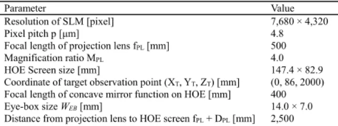
To confirm that the proposed method described in 2.3 is able to reproduce a holographic 3D image without any distor- tions especially for the longitudinal direction, the optical re- constructions of several target objects set at different depths were demonstrated. Main parameters of holographic projec- tion part are listed in Table 1.
Target objects were the plane characters of each depth value DR set at 0mm, 100mm, 500mm and 1,000mm with grid of background image at same depths. For simple cal- culation condition, sampling resolutions of wavefront at RSPPand RSPRwere fixed at the same resolution of SLM (7,680×4,320). 240×135 virtual cameras were uniformly ar- ranged at camera periodgRon each RSPR, and a set of view images at 32×32 pixels were rendered as ray information by rendering software[27]. YCM was derived as 68.8 mm by Eq. (4) and X, Y coordinates of each RSPR were in- versely calculated with precondition of coordinates of RSPP
as XP =0 andYP = 0, i.e. a center of each RSPPwas set at optical axis. Each coordinate of RSPPand RSPRof four target objects were derived by Eqs. (12)–(14) as listed in Ta- ble 2 with each lateral magnification ratioMPR.
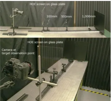
Figure 6 shows the optical setup of the HOE screen space with the camera set at a target observation point.
Figure 7 shows the optical reconstruction results of
Table 1 Main parameters of Projection-type holographic display.
Table 2 Coordinates of RSPPand RSPR.
Fig. 6 Experimental setup of the optical reconstruction.
Fig. 7 Optical reconstruction results of several depths. Each image is focusing depth at (a) 0 mm, (b) 100 mm, (c) 500 mm and (d) 1,000 mm from HOE screen.
each target object. The camera focused on the real seals put at each distance. It is clear that each object was correctly re- produced at designed depth without longitudinal distortion retaining the image resolution.
Then two sphere objects were reproduced at the same time by the proposed method and the conventional HS-based method demonstrated in Ref.[10]. In the case of the plu- ral target objects, layered RS plane method[28]can be di- rectly applied for the proposed method, namely RSPR and RSPPwere separately defined to each object and the wave- fronts propagated from each RSPPwere added on the SLM plane to generate one CGH. The distances of centers of each sphere object were set at 130 mm and 1,060 mm away from the HOE screen. The distances DR of two RSPRs were set at 100 mm and 1,000 mm, respectively. CGH of HS-
Fig. 8 Comparing results of conventional HS-based approach and the proposed method for the wide depth expression. (a)–(d): HS-based method, (e)–(h): the proposed method. The camera was focusing on the real seals put at 130 mm in (a), (b), (e) and (f), at 1,060 mm in (c), (d), (g) and (h).
based method can be calculated as setting RSPRat the HOE screen, i.e.DR =0 mm of RSPR, and after all calculations, such as ray sampling by camera and the conversion from ray information into the wavefront were executed on the HOE screen.
Figure 8 shows the results of optical reconstruction.
Figure 8 (a)–(d) were the HS-based method and (e)–(h) were the proposed method. By these experiments we can confirm that the arbitral depth expression consisting of plural objects can be reproduced by the proposed RS plane method, while conventional HS-based method is suffering to retain the im- age resolution for the distant object from the HOE screen.
4. Discussion and Conclusion
In this paper, the refined RS plane method designed for the projection-type holographic display was proposed. A geo- metric deformation characteristic from the SLM space to the HOE screen space, via the projection lens and the concave- mirror function implemented on HOE screen, was mathe- matically derived. To avoid the distortion of the final holo- graphic image, the coordinates of RS plane and the direc- tion of ray sampling were corrected to cancel out the defor- mation characteristic. The proposed method would be suit- able not only for our projection-type holographic display but also for a variety of other holographic 3D display systems that compose any deformation functions, such as rescale,
868
IEICE TRANS. ELECTRON., VOL.E101–C, NO.11 NOVEMBER 2018
convergence and divergence by using concave/convex lens and mirror. Moreover, the coordinate transformation de- scribed in 2.2 can be used for also the point/polygon-based approaches to reproduce the distortion-free holographic im- age for our projection-type holographic display.
In Fig. 8, there were small differences of the blurring performance between in-focus and out of focus area. This was caused by smallθFOVof the cameras at RSPRdue to the spatio-temporal resolution limitation of SLM. However, by developing the expansion technique of eye-box size men- tioned in introduction, the blurring behavior can become more natural to the observer.
A diffraction angleθscreenwas assumed same through- out the HOE screen as defined in Sect. 2. In fact, the signif- icant influence of this assumption was not observed in the optical experiment. The theoretical analysis of the influence of this assumption to the image quality will be handled in the future work.
In this paper, RSPR with the final holographic image was supposed to be formed behind the HOE screen as vir- tual image by satisfying Eq. (11). By setting the out of this condition, i.e.ZSLM<ZP, RSPRand the holographic image can be reproduced in front of the HOE screen as a floating real image close to the observer. Namely, the position of the holographic image for axial direction is not limited in both sides of the HOE screen while the image size is lim- ited inside of the HOE screen space depicted in Fig. 3. On the other hand, note that the size of display window, i.e. the size of the projected SLM, is not exactly limited, but has the trade-offrelationship with eye-box size related by Eqs. (1) and (2) under the condition that the spatio-temporal resolu- tion of SLM is fixed.
In the future work, the optimization of ray sampling pa- rameters, such as spatial and angular sampling periods, will be handled to improve the image quality for supposed ob- serving condition. Moreover, the development of full-color display system, and the expansion of the observable area by multiple-projection or the optical scanning of holographic projection will be also handled.
Acknowledgments
This work was supported by JSPS KAKENHI (Grant nos.
26790064, 16H01742 and 17K18425), the MIC/SCOPE (Grant no 162103005) and the Centre of Innovation Pro- gram from the Japan Science and Technology Agency, JST.
References
[1] P.S.t. Hilaire, et al., “Color images with the MIT holographic video display,” Proc. SPIE 1667, 73–84, 1992.
[2] H. Sasaki, K. Yamamoto, K. Wakunami, Y. Ichihashi, R. Oi, and T.
Senoh, “Large size three-dimensional video by electronic hologra- phy using multiple spatial light modulators,” Sci. Rep., vol.4, 6177, 2014.
[3] F. Yaras¸, H. Kang, and L. Onural, “Circular holographic video dis- play system,” Opt. Express, vol.19, no.10, pp.9147–9156, 2011.
[4] J. Hahn, H. Kim, Y. Lim, G. Park, and B. Lee, “Wide viewing angle dynamic holographic stereogram with a curved array of spatial light
modulators,” Opt. Express, vol.16, no.16, pp.12372–12386, 2008.
[5] Y. Takaki and Y. Hayashi, “Increased horizontal viewing zone angle of a hologram by resolution redistribution of a spatial light modula- tor,” Appl. Opt., vol.47, no.19, pp.D6–D11, 2008.
[6] R. H¨aussler, et al., “Large real-time holographic displays: from pro- totypes to aconsumer product,” Proc. SPIE 7237, 72370S, 2009.
[7] P.-A. Blanche, A. Bablumian, R. Voorakaranam, C. Christenson, W.
Lin, T. Gu, D. Flores, P. Wang, W.-Y. Hsieh, M. Kathaperumal, B.
Rachwal, O. Siddiqui, J. Thomas, R.A. Norwood, M. Yamamoto, and N. Peyghambarian, “Holographic three-dimensional telepres- ence using large-area photorefractive polymer,” Nature, vol.468, no.7320, pp.80–83, 2010.
[8] H. Sato, T. Kakue, Y. Ichihashi, Y. Endo, K. Wakunami, R. Oi, K.
Yamamoto, H. Nakayama, T. Shimobaba, and T. Ito, “Real-time colour hologram generation based on ray-sampling plane with multi- GPU acceleration,” Sci. Rep., vol.8, no.1, 1500, 2018.
[9] L. Onural, F. Yaras, and H. Kang, “Digital holographic three-dimen- sional video displays,” Proc. IEEE, vol.99, no.4, pp.576–589, 2011.
[10] K. Wakunami, P.-Y. Hsieh, R. Oi, T. Senoh, H. Sasaki, Y.
Ichihashi, M. Okui, Y.-P. Huang, and K. Yamamoto, “Projection- type see-through holographic three-dimensional display,” Nature Comm., vol.7, 12954, 2016.
[11] T. Yamaguchi, O. Miyamoto, and H. Yoshikawa, “Volume hologram printer to record the wavefront of three-dimensional objects,” Opt.
Eng., vol.51, no.7, 075802, 2012.
[12] W. Nishi and K. Matsuashima, “A wavefront printer using phase- only spatial light modulator for producing computer-generated vol- ume holograms,” Proc. SPIE 9006, 90061F, 2014.
[13] Y. Kim, E. Stoykova, H. Kang, S. Hong, J. Park, J. Park, and J. Hong,
“Seamless full color holographic printing method based on spatial partitioning of SLM,” Opt. Express, vol.23, no.1, pp.172–182, 2015.
[14] K. Wakunami, et al., “Wavefront printing technique with overlap- ping approach toward high definition holographic image reconstruc- tion,” Proc. SPIE 9867, 98670J, 2016.
[15] T. Senoh, et al., “Wide viewing-zone angle full-color electronic holography system using very high resolution liquid crystal display panels,” Proc. SPIE 7957, 795709, 2011.
[16] N. Fukaya, et al., “Expansion of the image size and viewing zone in holographic display using liquid crystal devices,” Proc. SPIE 2406, 283, 1995.
[17] M. Levoy and P. Hanrahan, “Light field rendering,” Proc.
SIGGRAPH ’96, pp.31–42, 1996.
[18] J.T. McCrickerd, “Comparison of Stereograms: Pinhole, Fly’s Eye, and Holographic Types,” J. Opt. Soc. Am. A, vol.62, no.1, pp.64–70, 1972.
[19] L.E. Helseth, “Optical transfer function of three-dimensional display systems,” J. Opt. Am. A, vol.23, no.4, pp.816–820, 2006.
[20] P. St Hilaire, “Modulation transfer function and optimum sampling of holographic stereograms,” Appl. Opt., vol.33, no.5, pp.768–774, 1994.
[21] I. Glaser and A.A. Friesem, “Imaging properties of holographic stereograms,” Proc. SPIE, 120, 150-162, 1977.
[22] M.E. Lucente, “Interactive computation of holograms using a look-up table,” J. Electron. Imaging, vol.2, no.1, pp.28–34, 1993.
[23] K. Matsushima and S. Nakahara, “Extremely high-definition full- parallax computer-generated hologram created by the polygon- based method,” Applied Optics 41, 34, 2009.
[24] K. Wakunami and M. Yamaguchi, “Calculation for computer gen- erated hologram using ray-sampling plane,” Opt. Express., vol.19, no.10, p.9086, 2011.
[25] J. Goodman, “Introduction to Fourier optics,” McGraw-Hill, 1996.
[26] R.P. Muffoletto, et al., “Shifted Fresnel diffraction for computational holography,” Optics Express, 15, 9, 2007.
[27] https://www.blender.org/
[28] K. Wakunami, et al., “Occlusion culling for computer generated hologram based on ray-wavefront conversion,” Optics Express 21, 19, 2013.
Koki Wakunami is a senior researcher at Electromagnetic Applications Laboratory, Ap- plied Electromagnetic Research Institute, Na- tional Institute of Information and Communica- tions Technology (NICT), Japan. He received his PhD degree in engineering from Tokyo In- stitute of Technology in 2013. He joined NICT as a researcher in 2013. His areas of interests include holography and autostereoscopic 3-D displays.
Yasuyuki Ichihashi received B.S., Ms. Eng.
and Ph. D. in 2005, 2007 and 2010 from the Chiba University in Japan. He was on loan to the Council for Science, Technology and Innovation of the Cabinet Office in 2015. He is currently a senior researcher at the National Institute of Information and Communications Technology (NICT), Japan. His research area is holography and its practical applications. He is a member of IEICE and ITE.
Ryutaro Oi is a senior researcher at Electromagnetic Applications Laboratory, Ap- plied Electromagnetic Research Institute, Na- tional Institute of Information and Communica- tions Technology (NICT), Japan. He received his PhD degree in science from the University of Tokyo in 2004. He was a visiting researcher at Japan Broadcasting Corporation (NHK) Sci- ence and Technology Research Laboratories in 2004 and 2005. He joined NICT as a researcher in 2006. His areas of interests include hologra- phy and autostereoscopic 3-D displays.
Makoto Okui received the B.S., M.E., and D.E. degrees from Tokyo Institute of Technol- ogy, Tokyo, Japan, in 1978, 1980, and 2006, re- spectively. He joined NHK (Japan broadcast- ing Corporation) in 1980. He conducted re- search and development on television technol- ogy including three-dimensional television at NHK STRL from 1983 to 2013. He is currently a Senior Researcher of the Electromagnetic Ap- plications Laboratory at the National Institute of Information and Communications Technol- ogy (NICT) of Japan.
Boaz Jessie Jackin received his Ph.D from the Center for Optical Research and Education, Utsunomiya University in 2013 and then con- tinued as a Post-Doc researcher in the same uni- versity until 2016. Since 2016, He works as a researcher at the National Institute of Informa- tion and Communications Technology (NICT) in Japan. His current research interest includes, computer generated holography, digital hologra- phy and light field display.
Kenji Yamamoto received his PhD from Nagoya University, Japan, in 2007. He is a chief senior researcher at Applied Electromag- netic Research Institute, NICT. His research interests include 3-D and ultra-realistic visual system, especially electronic holography, wave- front printer, computer-generated hologram, In- tegral Photography, multi-camera system, multi- view video coding, depth estimation, and view synthesis.