Ground Vehicle and UAV-empowered DTN
Protocols for Information Sharing in
Post-disaster Scenarios
Zhaoyang Du
A Thesis Submitted for the Degree of
DOCTOR OF PHILOSOPHY
THE UNIVERSITY OF ELECTRO-COMMUNICATIONS
2021
Ground Vehicle and UAV-empowered DTN
Protocols for Information Sharing in
Post-disaster Scenarios
by
Zhaoyang Du
Supervisory Committee:
Prof. Tsutomu Yoshinaga
Assoc. Prof. Hisashi Koga
Assoc. Prof. Chenggao Han
Assoc. Prof. Koichi Adachi
Assoc. Prof. Satoshi Ohzahata
Assoc. Prof. Celimuge Wu
Graduate School of Informatics and Engineering
The University of Electro-Communications
ii
車両・無人航空機を活用した災害時情報共有のための
DTN プロトコル
和文概要
地震災害時においては,通信インフラが故障し,携帯電話ネットワークが利用でき
なくなることが予想される.そのため,災害時における通信方式の検討が必要となる.
遅延耐性ネットワーク(Delay Tolerant Networking:DTN)技術は継続的なネットワー
ク接続が不可能な極限的環境における通信をサポートすることができ,災害時にお
ける携帯基地局に依存しない情報共有が可能となる.本研究では,車両・無人航空
機(Unmanned Aerial Vehicle: UAV)を活用した災害時情報共有のための DTN プロ
トコルの研究を行っている.車両・UAV の移動性を十分活用し,自律分散通信技術
で災害時における情報共有を実現することを目的としている.
本論文では,ア)車両 DTN ネットワークにおけるメッセージ中継プロトコルとバッフ
ァ管理方式,イ)UAV を活用したメッセージ転送方式,といった2点に焦点を当て,
下記2つの手法を提案している.1 つ目は,車両間の接触履歴に基づき,ネットワー
クノード間の将来の接続確率を予測し,それに合わせたメッセージの複製方式を提
案している.また,各ノードのバッファ(Buffer)をより効率的に利用するために,デー
タの重要度やバッファの空き領域を統合的に考慮したバッファ管理手法を提案して
いる.情報共有プロセスにおいては,メッセージの中継方式とバッファ管理を連携さ
せることで,パケット到達率の向上と遅延の削減を実現している.
2つ目は,車両・UAV 両方を活用した DTN プロトコルを提案している.UAV は各
地域間で巡航して,フェリーノード(中継ノード)として地域間でのメッセージ転送を
iii
サポートするシナリオを想定している.提案方式は,UAV と車両の移動パターンの
違いに焦点をあて,まず目的ノードに届く確率の予測を行う.特に,従来方式では,
確率の予測においては,接触回数のみを考慮していることに対して,本研究では,
接触回数に加えて毎回の接触時間を考慮している.その次に,予測確率及びメッセ
ージの優先順位を統合的に考慮し,UAV を利用するか否か,どの UAV を利用する
かといったデータ転送の決断を行う.また,災害時における道路損傷も考慮し,UAV
を利用して孤立地域間の情報共有を可能とするシナリオにおける通信性能の検証
を行っている.
The ONE Simulator を利用して,実際の地図データに基づいた現実的な車両移
動シナリオを構築し,提案プロトコルの性能を評価している.既存の DTN プロトコル
である“PRoPHET,” “Spray-and-Wait,” “Bubble Rap”と比較することで提案方式の
優位性を十分示している.
上記のように,本論文は,災害時における通信を想定し,車両・無人航空機を活
用した DTN プロトコルを提案し,現実的なネットワークシミュレーションを用いて既存
手法と比較しながら,提案手法の有効性を確認している.
iv
Table of Contents
Ground Vehicle and UAV-empowered DTN Protocols for Information Sharing in Post-disaster
Scenarios ... i
List of Figure ... vi
List of Table ... vii
1 Introduction ... 1
1.1 Research background ... 1
1.2 Vehicular delay tolerant networks ... 5
1.3 UAVs in DTN ... 7
1.4 Contribution ... 9
1.5 Organization of the thesis ... 10
2 VDTN and related technology ... 11
2.1 Routing protocols in VDTN ... 11
2.2 Replication-based routing protocols in VDTN ... 12
2.2.1 Single-copy routing protocols in VDTN ... 12
2.2.2 Multi-copy routing protocols in VDTN ... 14
2.3 Historical-based routing protocols in VDTN ... 17
2.4 Social-awareness routing protocols in VDTN ... 19
2.5 Buffer management in VDTN ... 22
2.5.1 Buffer management based on the sender ... 23
2.5.2 Buffer management based on the receiver ... 27
2.5.3 Buffer management based on node cooperation ... 34
2.6 Studies of UAVs in VDTN ... 38
2.6.1 The introduction and characteristics of the ferry node ... 38
2.6.2 UAV technologies in VDTN ... 40
2.7 DTN technologies in the post-disaster scenario ... 42
2.8 Conclusion ... 43
3 A VDTN scheme with enhanced buffer management... 45
3.1 Problem discussion ... 46
3.2 PRoPHET-based VDTN routing protocol ... 47
3.3 The time complexity of the proposed routing protocol ... 51
3.4 Proposed buffer management policy ... 51
3.4.1 The network model ... 52
3.4.2 Buffer overhead ratio ... 53
3.4.3 Time measurement ... 54
3.4.4 Estimation delivery successful value ... 54
3.4.5 Congestion control metric ... 55
3.4.6 Proposed buffer management algorithm ... 56
3.5 The time complexity of proposed buffer management ... 58
3.6 Fairness issue in DTN routing protocols ... 59
3.7 Simulation and result ... 60
v
3.7.2 Simulation Set up ... 63
3.7.3 Simulation result ... 65
3.8 Analysis of post-disaster DTN environment ... 80
3.8.1 Introduction of the regional center node ... 81
3.8.2 Simulation and result ... 83
3.9 Conclusion ... 88
4 UAV-empowered protocol in VDTN ... 90
4.1 Problem discussion ... 91
4.2 Proposed routing protocol ... 93
4.2.1 Definition of the persistent connection time ratio ... 93
4.2.2 Proposed message delivery process ... 95
4.3 The time complexity of the proposed routing protocol ... 100
4.4 Simulation and result ... 100
4.4.1 Simulation set up ... 100
4.4.2 Simulation result ... 103
4.5 Analysis of post-disaster DTN environment ... 114
4.5.1 Analysis of post-disaster application scenarios... 114
4.5.2 Simulation set up ... 115
4.6 Conclusion ... 123
5 Conclusion and future work ... 125
5.1 Conclusion ... 125
5.2 Future work ... 127
Reference ... 128 List of Abbreviation ... I Author Biography ... III List of Publication ... IV
vi
List of Figure
Figure 1-1 The difference in architecture. ... 2
Figure 1-2 Message custody transportation. ... 3
Figure 1-3 Message delivery process in DTN. ... 4
Figure 1-4 A VDTN scenario. ... 6
Figure 1-5 UAV ferry nodes in VDTNs. ... 8
Figure 2-1 Message delivery process of the first contact routing protocol. ... 13
Figure 2-2 Message delivery process of the direct delivery routing protocol. ... 14
Figure 2-3 Message delivery process of the Epidemic routing protocol. ... 15
Figure 2-4 Message delivery process of the Spray-and-Wait routing protocol. ... 16
Figure 2-5 Data forwarding process of the social-awareness routing protocol. ... 20
Figure 2-6 DTN buffer management algorithm classification. ... 23
Figure 2-7 Example of a ferry node... 39
Figure 3-1 Message delivery process of the proposed routing protocol. ... 48
Figure 3-2 Flowchart of the proposed routing scheme. ... 49
Figure 3-3 Message forwarding in the actual scene. ... 51
Figure 3-4 Network model. ... 52
Figure 3-5 Cache status of source node S. ... 53
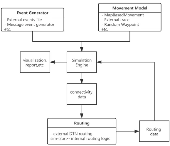
Figure 3-6 The software architecture of ONE. ... 61
Figure 3-7 Packages of ONE. ... 62
Figure 3-8 The map of Helsinki in The ONE. ... 63
Figure 3-9 Drop probability for the various value of α. ... 66
Figure 3-10 Delivery probability for various buffer sizes. ... 69
Figure 3-11 Overhead ratio for various buffer sizes. ... 69
Figure 3-12 Average latency for various buffer sizes. ... 70
Figure 3-13 Delivery probability for various message intervals. ... 71
Figure 3-14 Overhead ratio for various message intervals. ... 72
Figure 3-15 Average latency for various message intervals. ... 72
Figure 3-16 Delivery probability for various message TTL. ... 74
Figure 3-17 Overhead ratio for various message TTL. ... 74
Figure 3-18 Average latency for various message TTL. ... 75
Figure 3-19 Delivery probability for various numbers of nodes. ... 76
Figure 3-20 Overhead ratio for various numbers of nodes. ... 77
Figure 3-21 Average latency for various numbers of nodes. ... 77
Figure 3-22 Delivery probability for various buffer sizes. ... 79
Figure 3-23 Overhead ratio for various buffer sizes. ... 79
Figure 3-24 Average latency for various buffer sizes. ... 80
Figure 3-25 Post-disaster DTN environment with regional center node. ... 82
Figure 3-26 Patrol route for rescue vehicle nodes. ... 83
Figure 3-27 Delivery probability for various numbers of rescue vehicles. ... 87
vii
Figure 3-29 Average latency for various numbers of rescue vehicles. ... 88
Figure 4-1 Forwarding decision scenario A. ... 92
Figure 4-2 Forwarding decision scenario B. ... 93
Figure 4-3 Communication link between nodes. ... 94
Figure 4-4 The encounter times of two nodes. ... 95
Figure 4-5 Comparison of the UAV-vehicle communication link and the inter-vehicle link. ... 95
Figure 4-6 The selection of a relay node in the proposed protocol. ... 97
Figure 4-7 Message forwarding in a post-disaster scenario. ... 99
Figure 4-8 Patrol route of UAVs. ... 102
Figure 4-9 Delivery probability for the various value of α. ... 103
Figure 4-10 Delivery probability for various numbers of UAVs. ... 105
Figure 4-11 Overhead ratio for various numbers of UAVs... 106
Figure 4-12 Average latency for various numbers of UAVs. ... 106
Figure 4-13 Average hop count for various numbers of UAVs. ... 107
Figure 4-14 Delivery probability for various numbers of nodes. ... 109
Figure 4-15 Overhead ratio for various numbers of nodes. ... 109
Figure 4-16 Average latency for various numbers of nodes. ... 110
Figure 4-17 Average hop count for various numbers of nodes. ... 110
Figure 4-18 Delivery probability for various numbers of UAVs. ... 112
Figure 4-19 Overhead ratio for various numbers of UAVs. ... 113
Figure 4-20 Average latency for various numbers of UAVs. ... 113
Figure 4-21 Average hop count for various numbers of UAVs. ... 114
Figure 4-22 Post-disaster emergency communication network based on DTN. ... 115
Figure 4-23 The simulation scenario. ... 117
Figure 4-24 Delivery probability for various numbers of UAVs. ... 119
Figure 4-25 Overhead ratio for various numbers of UAVs. ... 119
Figure 4-26 Average latency for various numbers of UAVs. ... 120
Figure 4-27 Delivery probability for various numbers of UAVs. ... 122
Figure 4-28 Overhead ratio for various numbers of UAVs. ... 122
Figure 4-29 Average latency for various numbers of UAVs. ... 123
List of Table
Table 1 Simulation setting and parameters ... 64Table 2 Parameters for routing algorithms ... 64
Table 3 Simulation parameters ... 65
Table 4 Simulation settings and parameters for regular nodes. ... 84
Table 5 Simulation parameters for rescue vehicle nodes. ... 85
Table 6 Simulation parameters for regional center nodes. ... 85
viii
Table 8 Simulation parameters for UAVs. ... 102
Table 9 Simulation settings and parameters for regular nodes. ... 116
Table 10 Simulation parameters for UAVs. ... 117
ix
Abstract
In recent years, natural disasters frequently occur all around the world. When a disaster happens, the communication infrastructure may break down, and then the mobile phone network becomes unavailable. Therefore, it is imperative to study the communication problem in catastrophe scenarios. Delay Tolerant Networks (DTNs) can support communication in extreme environments where a continuous network connection is impossible, and enable information sharing among users without relying on base stations in a disaster. This thesis studies the DTN protocol for information sharing using vehicles and unmanned aerial vehicles (UAVs) in typical and disaster scenarios. The purpose is to fully utilize vehicles and UAVs' mobility and realize information sharing with autonomous distributed communication technologies.
This thesis includes two main technical contributions: a) a message relay protocol and buffer management scheme in Vehicular Delay Tolerant Network (VDTN), and b) a message forwarding strategy using UAVs in urban scenarios. The first one proposes a routing protocol based on the contact history between vehicles that could be used to predict the future connection probability between network nodes. To use the buffer of each node more efficiently, a buffer management policy is also proposed to consider the importance of data and the buffer size jointly. The thesis aims to improve the packet arrival rate and reduce the latency by linking the message forwarding strategy and buffer management in the information sharing process. Extensive computer simulations are conducted to show that the proposed routing scheme achieves better system performance than the existing baseline routing protocols.
Secondly, a VDTN protocol that utilizes both vehicles and UAVs is proposed. A scenario where UAVs cruise between regions and support message forwarding as ferry nodes is considered. The proposed protocol focuses on the different movement patterns between UAV and vehicles, and predicts the message forwarding delay until it reaches the destination node. Next, the expected delay time and the priority of the message are considered jointly in making the data transfer decision about whether to use UAV or not. In addition, considering road damages in a disaster, the communication performance for information sharing between
x isolated areas using UAVs is verified.
The thesis constructs a realistic vehicle movement scenario based on actual map data and evaluates the proposed protocol's performance using the Opportunistic Networking Environment (ONE) simulator. The superiority of the proposed scheme is demonstrated by comparing it with the existing DTN protocols.
xi
Acknowledgments
I would like to express my gratitude to all those who helped me during the writing of this thesis.
Firstly, my deepest gratitude goes first and foremost to Associate Professor Celimuge Wu, my supervisor, for his constant encouragement and guidance. He has walked me through all the stages of the writing of this thesis. Without his consistent and illuminating instruction, this thesis could not have reached its present form.
Secondly, I would like to thank the supervisory committee of my thesis defense, Professor Tsutomu Yoshinaga, Associate Professor Hisashi Koga, Associate Professor Chenggao Han, Associate Professor Koichi Adachi, and Associate Professor Satoshi Ohzahata for their valuable comments and guidance about this paper.
Thirdly, I would like to thank all the members in the Celimuge Lab. It is their kind help and support that have made my study and life in Japan a wonderful time.
Finally, I must express my very profound gratitude to my parents and my wife for providing me with unfailing support and continuous encouragement throughout my years of study and through the process of researching and writing this thesis. This accomplishment would not have been possible without them. Thank you.
1
Chapter 1
1 Introduction
At the beginning of the thesis, this chapter introduces the research about delay tolerant networks (DTNs) and unmanned aerial vehicles (UAVs). The framework of this chapter is shown below. Section 1.1 introduces the background of the research and DTN technologies. Section 1.2 presents the development of vehicular delay tolerant networks (VDTNs) in recent years and problems to be solved. Section 1.3 introduces the use case of UAVs in DTN scenarios. The contributions of this thesis are list in section 1.4. Section 1.5 explains the organization's overview of the thesis.
1.1 Research background
The classic TCP/IP protocol can be successfully applied to the Internet depending on the following characteristics of physical links [1][2].
(1) At the same moment, an end-to-end path exists between the source node and the destination node.
(2) The round trip time (RTT) between any pair of nodes in the network cannot be too long.
(3) The network transmission is reliable, and the packet loss rate is low.
(4) Upper-layer applications do not have to worry about communication performance.
In recent years, a new kind of network called Challenge Networks has sprung up [3-8]. These networks may have intermittent connections due to sparse nodes, high-speed mobility, the alternating activity of nodes, radio silence for security reasons, or malicious attacks. These networks have high latency and low data rates in communication links, may not have stable end-to-end connections, and network nodes' resources are limited. These network features break the TCP/IP model's assumptions introduced above and made the current TCP/IP model
2
not well applied to these networks [9][10]. Therefore, researchers proposed a new network architecture called Delay Tolerant Network (DTN) to adapt to these new network characteristics [11].
As shown in Figure 1-1, a message-oriented bundle layer is added between the transport layer and the application layer to overcome the impact of network interruption through persistent storage in the DTN architecture. A hop-by-hop reliable delivery and elective end-to-end acknowledgments to supports network interoperability through a flexible naming mechanism (based on uniform resource identifiers) is added. In addition, it also contains an optional security model to prevent unauthorized use of network devices [12][13]. If a relay node storing the message is offline during the transmission, the message could be stored in relay nodes and transmit to other network nodes whenever the relay node reconnected to the network [14].
Figure 1-1 The difference in architecture.
The bundle layer could provide essential services such as message delivery in DTN by unicast mode. In order to enhance the reliability of the transport, custody transportation was adapted in the bundle layer. Custody transportation is a coarse-grained retransmission mechanism that transfers the responsibility for reliably transferring messages between nodes. A single transfer of a message between nodes is called single custody transportation. The
3
node that receives the message and agrees to assume responsibility for its reliable delivery is called a custody node. The custody transportation is initiated by the source node and occurs between layers of neighbor nodes, as shown in Figure 1-2. When message delivery is required, the current custody node transfers the request and initiates a reply time retransmission timer. If the relay node agrees to receive the message and store it in the future, it will send a reply. If no response is returned, the retransmission of the message will start. The custody node usually needs to store the message continuously and cannot be dropped unless another node is found to take over the custodian responsibility or the message TTL (Time to Live) expires. However, custody transportation does not guarantee end-to-end reliability, which is only possible if the source node receives an acknowledgment from the neighbor node after requesting custody transportation [15].
Figure 1-2 Message custody transportation.
The DTN is a network in which the distribution of nodes is sparse. Thus, the delivery of messages is mainly realized by encounters caused by node movement. Since the DTN node is intermittently connected, messages cannot be delivered to the target directly; thus, the relay node is needed to complete the message delivery [16]. As shown in Figure 1-3, the source node
S has a message that needs to be forwarded to the destination node D. At time t1, the source
node and the destination node are located in two different areas. Two nodes cannot forward the message through direct communication, so the source node S needs to find a relay node to
4
deliver it. At time t2, node 3 can communicate with node 4 and forward the message. At time t3, node 4 moves into the communication range of destination node D and delivers the message to destination node D. This is the complete delivery process of the message in DTN.
Figure 1-3 Message delivery process in DTN.
As mentioned above, DTN is not based on existing assumptions about transmission links, so DTN has the following characteristics different from traditional TCP/IP networks:
(1) Intermittent connection: the reasons for the intermittent connection of DTN nodes include the limited bandwidth, the uncertainty movement and the sparseness deployment of nodes. The source node cannot directly transfer messages to the destination node for the above reasons, affecting the delivery probability of messages. Only when nodes are within the communication range can they initiate a communication request and deliver the message. The intermittent connection is a primary DTN feature and an essential prerequisite for DTN routing research [17].
(2) Node resources are limited: DTN nodes are often distributed in extreme environments. The node resources are limited by weight, the power supply, or other equipment carried that restrict the use time of the node. Usually, DTN nodes have to adopt a specific strategy to save limited resources [18].
(3) Long latency: the forwarding of messages in DTN needs to use relay nodes, and the messages will be delivered through the random movement of relay nodes. For the intermittent connection characteristics of DTN, the nodes temporarily store the messages in their cache. The source node is able to accomplish the message transferring by using relay nodes, resulting in a long delivery delay [19].
5
(4) Rapid changes in network topology: Compared with the traditional Internet, DTN nodes have random mobility. The spontaneous movement of nodes makes the network topology changed frequently. The random increase and decrease of nodes, the exhaustion of node energy, and the harsh communication environment will continuously change the network topology [20].
Because DTN is always in a harsh and challenging environment, the success rate of message delivery has a great relationship with the choice of a routing protocol. A perfect routing process can significantly improve the success rate of message delivery. Therefore, the research on the DTN routing protocol has always been a hot spot [21-23]. Through the key research on the structure and characteristics of DTN, researchers have proposed several typical routing algorithms, such as flooding-based routing [24], historical-based routing [25], and social-awareness routing [26]. These routing algorithms have a good effect on processing the specific characteristics of the DTN and can ensure the success rate of message delivery.
1.2 Vehicular delay tolerant networks
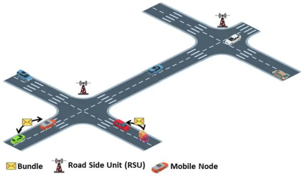
As shown in Figure 1-4, the VDTN is a special self-organized network. Due to the intermittent and opportunistic connections between nodes in VDTNs, it has the characteristics of DTN, and the routing strategy is more challenging than that in DTNs. Through vehicle to vehicle (V2V), vehicle to infrastructure (V2I) communications in VDTNs, the information exchange between drivers can be effectively promoted. The main application services provided by VDTNs fall into three categories: traffic safety, traffic management, and value-added services [27] [28].
6
Figure 1-4 A VDTN scenario.
Traffic safety services are the primary and most valuable application services for VDTNs. Through V2V and V2I communications, real-time information can be exchanged periodically. Real-time information mainly includes the movement state of nodes (such as the current speed of nodes, the position of nodes), and surrounding traffic conditions (such as the number of surrounding nodes). By analyzing real-time information, drivers can detect potential hazards around them and take appropriate emergency measures. The application is mainly used to improve the traffic safety of urban roads and avoid traffic accidents such as rear-end collision and side hanging. Typical applications include collaborative collision warning, collaborative lane reservation, and post-accident warning [29].
Traffic management services realize the monitoring of road traffic status through collaborative perception between vehicles or based on the movement of detected cars. For traffic management, the traffic status information can be centrally processed through the traffic control center, and the traffic can be effectively dispatched. The vehicle can re-plan the route based on the real-time traffic status information obtained [30].
Traffic value-added service is a new type of VDTN service application, mainly through the message transmission between vehicles to provide drivers with diverse mobile communication content, mobile sharing, and multimedia entertainment services, thereby increasing the fun in
7
the driving process. However, since its service content needs to occupy a large amount of network bandwidth and needs to be compatible with traditional Internet service applications, the service quality needs to be improved [31].
1.3 UAVs in DTN
In the VDTN environment, the communication distance of V2X (vehicle to everything) is limited by the surrounding environment. The vehicle speed is fast, the network topology changes quickly, and the RSU (roadside unit) carries great pressure, causing data congestion, information transmission lag, and reducing network performance. In addition, network performance may be affected by low communication quality and network partitioning in some extreme environments, such as areas where infrastructure is damaged by earthquakes, fires, or floods. Besides, due to obstacles or complex terrain, the quality of the V2X link is likely to be reduced or even obstructed in the worst case.
Unmanned aerial vehicles (UAVs) have great potential in enhancing the performance of the mobile communication system due to their advantages over vehicles or mobile devices [32-34]. It has been widely used in traffic monitoring, disaster rescue, military reconnaissance, and other fields. The combination of UAVs and VDTNs to form an integrated collaborative network can further enhance the information interaction capability of VDTN. First, UAVs can extend the information dimension of ground vehicles. Secondly, the UAV group dispatched to the target area can quickly build a network and provide timely network services for ground vehicles. Finally, when the V2X link is interrupted, the UAV can act as an aerial base station to set up a relay channel for the ground network [35-37]. The deployment of the UAV ferry nodes in the VDTN is shown in Figure 1-5.
8
Figure 1-5 UAV ferry nodes in VDTNs.
The UAV-assisted VDTN takes UAV as relay nodes, which can receive and forward data uploaded by ground users, thus improve the reliability of wireless communication links, enhance infrastructure flexibility, and provide communication coverage for areas without networks. The architecture was originally proposed to be mainly used in military fields, such as unmanned tanks and UAVs, for joint operations to improve the judgment of decision-makers due to information asymmetry and thus achieve tactical victory. In recent years, this architecture has been gradually applied to civil industries such as intelligent transportation systems [38], earthquake relief [39], and precision agriculture [40], especially the rapid development of IoT and the 5G industry, which has set off a wave.
The architecture of UAV assisted VDTN usually considers the collaborative control between UAV and UAV (U2U), UAV and cloud (U2C), UAV and vehicle (U2V), and UAV and ground base station (U2G). The introduction of UAV in DTN can provide more reliable services for vehicle nodes and mobile device nodes to meet the needs of message forwarding. Flexible use of UAV nodes is the key to improving network performance.
9
1.4 Contribution
The aim of this thesis is to design a routing protocol to support large traffic, low latency, and diverse application in the VDTN.
According to the reasons mentioned above, a VDTN-based routing protocol and a specific buffer management algorithm to support handling redundant messages in the cache are proposed in this thesis. Furthermore, a protocol is presented that enables more effective use of UAVs in VDTN environments.
For the VDTN-based routing protocol, the contributions are as follow:
An improved routing algorithm based on the encounter probability calculated by PRoPHET and combined with a binary Spray-and-Wait copy control strategy is proposed in this paper. Simulation results show that the new algorithm improves the message delivery rates while reducing overhead ratio and delay.
A specific buffer management algorithm designed for the PRoPHET Based protocol is proposed to improve its congestion mitigation policy. In the algorithm, the impact of the message on the cache, the time factor of the message, and the probability of the message being forwarded to the destination node are comprehensively considered to construct the congestion control metric (CCM). In the node's buffer, each message copy is sorted according to the CCM value. In order to improve the efficiency of buffer utilization, messages with higher CCM will be forwarded first. When congestion happens in the node, the message with the smallest CCM is dropped to reduce the impact of unreasonable message dropping on network performance. For the UAVs algorithms, the contributions are as follow:
Improve the forwarding probability factor. The routing algorithm based on the time factor defines the persistent connection time ratio extracted by analyzing the connection mode of two nodes. The encounter probability in the traditional probabilistic routing algorithm is improved by considering the influence of the time factor. In the message forwarding process, the next-hop node is selected according to the improved encounter probability.
10
A new routing protocol for UAV assisted VDTN environment is proposed. The proposed protocol considers the persistent connection time between nodes in the message forwarding decision. With the intelligent method of choosing relay nodes, the proposed protocol enables a more effective use of UAVs in DTN environments.
1.5 Organization of the thesis
The remainder of the thesis is organized as follows: In Chapter 2, the introduction of DTN-related technology is presented, including existing routing protocols, buffer management, and the use of UAVs in the DTN environment.
In Chapter 3, a new routing protocol for VDTN is proposed. The proposed protocol takes into account the encounter probability between nodes and the number of copies of the message in the forwarding decision. A local optimal buffer management drop strategy based on the proposed protocol is also investigated, which combines the delivery successful estimation, time measurement and buffer overhead ratio to calculate the congestion control metric (CCM) value. The CCM value is the parameter that controls the message drop policy to reduce the impact of blindness message drop to the delivery rate. The effectiveness of the routing protocol is verified by observing network performance evaluation metrics such as message delivery rate and network overhead.
In Chapter 4, a new routing protocol for UAV assisted vehicular DTN is proposed. The proposed protocol considers the persistent connection time ratio between nodes in the message forwarding decision. With the intelligent method of choosing relay nodes, the proposed protocol enables a more effective use of UAVs in DTN environments. Simulations in typical scenes and post-disaster scenes were carried out. Extensive simulations in various scenarios confirm the advantage of the proposed protocol over existing baselines in terms of message delivery ratio, network overhead, and end-to-end delay.
11
CHAPTER 2
2 VDTN and related technology
In section 2.1, the classification of routing protocol in VDTNs is introduced. Sections 2.2-2.4 introduce replication-based routing protocols, historical-based routing protocols, and social-awareness routing protocols, respectively. Section 2.5 lists the related research about the buffer management scheme for VDTN. Related studies about UAVs in the VDTN environment is explained in section 2.6. Section 2.7 introduces several DTN technologies in the post-disaster scenario. Finally, section 2.8 concludes this chapter.
2.1 Routing protocols in VDTN
Routing refers to the successful delivery of the packet to the destination node by finding a connected path based on the known network information stored in the node. Routing mainly consists of two primary actions: confirm the connecting path and message transmission. There is a complete and stable end-to-end path between the source node and the destination node in the traditional network, but there is no such path in VDTNs. Therefore, VDTN cannot apply traditional routing protocols. Due to the sparse distribution of VDTN nodes and random movement of nodes, network segmentation is easy to occur, and communication between nodes is inconvenient. Therefore, nodes need to transfer messages to relay nodes and repeat this process until the message is delivered to the destination node. Routing algorithm research is the most important and basic content of DTN data transmission and is the most fundamental guarantee of data delivery [41-43].
The traditional Internet routing protocol cannot be applied to VDTNs. According to the sparse distribution of VDTN nodes and the random movement of nodes, a suitable routing protocol is required to meet the communication needs. Researchers have proposed several innovative and effective routing algorithms.
The VDTN routing protocol could be divided into replication-based routing protocols, historical-based routing protocols, and social-awareness routing protocols. The
12
replication-based routing protocol includes single-copy routing protocols and multi-copy routing protocols. The single-copy routing protocols refer to the fact that there is only one copy of the same message in the whole network, and the node will only deliver the message to the appropriate relay node. Because there is only one copy of the message in the network, the message delivery rate is low, the delay is large, and the message is easy to lose. Multi-copy routing protocols mean that there are multiple copies of the same message in the whole VDTNs [44]. If one copy is delivered to the destination node, the delivery will be considered successful. At present, multi-copy routing is mostly adopted in the VDTN routing algorithm because it could improve the success rate of message delivery and reduce the communication delay. In the historical-based routing protocol, a node maintaining some network information related to other nodes to establish an Ego Network [45]. Thus, the social connection or characteristics between nodes are measured, and the utility function is calculated. Then, the utility function is used to select the satisfactory forwarding node. Social-awareness routing protocols take the social connections and attributes between nodes as the primary basis for routing design [46]. Compared with the frequent movement of nodes, the social contact between nodes shows relative stability and regularity. As a result, social connections become a more rational way to predict future meeting opportunities.
2.2 Replication-based routing protocols in VDTN
2.2.1 Single-copy routing protocols in VDTN
In single-copy routing protocols, a node does not remain the message copy after delivering it to the relay node, so there is only one copy of the message in the whole network. Single-copy routing protocols take up fewer network resources and use less storage space to reduce the network load. However, only one copy of the message exists in the network, which
significantly reduces the delivery success rate of the message, increases network overhead and the delivery delay. Therefore, there are not many studies on the single-copy routing algorithm. Two typical routing algorithms will introduce below: first contact routing protocol and direct delivery routing protocol.
(1) First Contact routing protocol (FC) [47]: After a message is created by the source node, it stores the message in its cache and carries the message moving randomly. During the process of movement, the message will be delivered to the first node it meets (no matter whether the node is the destination node or not). The source node will
13
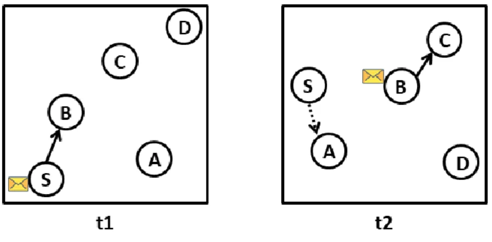
randomly deliver the message to one node when there is more than one node within the transmission range. The relay node will continue to carry the message to move randomly and deliver it in the same way until it is successfully transferred to the target. The message delivery process of the first contact routing protocol is shown in Figure 2-1.
Figure 2-1 Message delivery process of the first contact routing protocol.
A message created in the source node S, and its destination node is D. The destination node
D is not in the communication range of S. At t1, S meets node B. Whether node B is the
destination node or not, S will deliver the message to B, and B will store it in the cache space and move continuously. At t2, node B carrying the message meets node C, and B delivers the message to node C. Source node S meets node A, and no message is delivered because there is no stored message in S. Node C will transfer the message in the same way, to deliver the message to the destination node D.
The first contact routing algorithm cannot predict the path between the source node and the destination node. Therefore, the message delivery success rate is low, and the delay is huge.
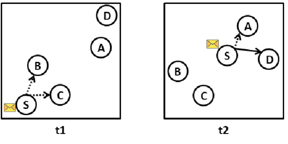
(2) Direct Delivery routing protocol (DD) [48]: The main idea is that the source node generates and stores messages in the cache, and the node carries messages to move until it meets the destination node. The message delivery process of direct delivery routing is shown in Figure 2-2.
14
Figure 2-2 Message delivery process of the direct delivery routing protocol.
A message created in the source node S, and its destination node is D. Since the destination node D is not in the communication range of S, S will store and carry the message to move randomly. At t1, S meets with nodes B and C. Since neither node B nor node C is the destination node, S will ignore node B and node C and continue moving. At t2, node A and destination node D appear in the transmission range of node S. At this time, S delivers the message directly to node D.
Since this routing algorithm only relies on the source node and the destination node to meet directly in the network, the success rate of the message delivery is low. In a real network environment, direct delivery routing is likely to result in message delivery failure.
2.2.2 Multi-copy routing protocols in VDTN
Due to frequent network segmentation in the DTN, just keep one message copy in the entire network is extremely easy to cause delivery failure. Therefore, send the replica of a message to relay nodes could improve the success rate of message delivery. There will be multiple transmitting copies of the same message in the network at the same time. The proposal of multi-copy routing can significantly improve the success rate of message delivery and reduce network latency. Compared with single-copy routing, multi-copy routing has an advantage under the condition that various network resources are abundant. Therefore, researchers have done many studies on multi-copy routing. Typical multi-copy routing protocols will introduce below.
15
multi-copy routing protocol used in DTN. It is mainly aimed at the intermittent connection of nodes in DTN, which increases the probability of successful message delivery by increasing the number of messages copies in the network. In the Epidemic routing protocol, as long as the source node encounters another node that does not have the message, it will send one copy. The relay node will deliver the message in the same way until it is given to the destination node. The delivery process of the Epidemic routing message is shown in Figure 2-3.
Figure 2-3 Message delivery process of the Epidemic routing protocol.
A message is created in the source node S that the destination is node D. At t1, S encounters nodes B and C, S duplicates the message and delivers the copy of the message to nodes B and
C. At t2, node B meets node A and node C meets node D, nodes B and C will deliver the
message copy to the node they meet. Since the message has been delivered to the target, the message delivery process has ended.
The Epidemic routing is suitable to work in network environments where the network size and data traffic are small. Still, the network communication bandwidth and node cache space are large enough. At this point, the Epidemic routing can significantly enhance the delivery probability and lessen the transmission delay. However, it will consume many network resources, including network bandwidth and the use of nodes cache.
(2) Spray-and-Wait routing protocol [50]: In order to solve the severe consumption of network resources caused by the redundancy of the message copy in the flood routing algorithm, the Spray-and-Wait routing protocol uses a specific strategy to limit the
16
message copy while forwarding the message. This algorithm only generates a small number of message copies in the network for forwarding to ensure that the total number of message transmissions can be controlled. Then each message copy will be independently forwarded according to a more effective single-copy routing algorithm. The Spray-and-Wait routing protocol can be regarded as a compromised algorithm between single copy routing algorithm and flood routing algorithm.
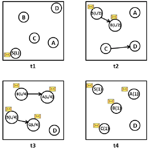
The message transfer process of the Spray-and-Wait routing is shown in Figure 2-4. From t1 to t3 is the spray phase, during which the node with the message will send half of the message copy to the node that does not contain it. The t4 is the wait phase. At this time, the message will only be transmitted to the destination node.
Figure 2-4 Message delivery process of the Spray-and-Wait routing protocol.
In Figure 2-4, at t1, a message is created in the source node S and replicate L copies. At t2, S meets node B delivers L/2 copies. At t3, node S meets node C and node B meets
17
node A. Node S and node B will give half of their L/2 copies to C and A, so each node has L/4 copies of the message. At t4, every node only has one message copy, so it enters the wait phase. The message will only be transferred to the destination node.
2.3 Historical-based routing protocols in VDTN
In the VDTN, each vehicle may have a particular movement rule. For this reason, the researchers propose the probabilistic routing algorithm. The PRoPHET (Probabilistic routing protocol using the history of encounters and transitivity) routing is a routing algorithm based on the historical encounter information of nodes. Each node in the network maintains an encounter probability table that records the probability of meeting between the node and other network nodes. When two nodes encounter, each node will update its probability table. If the probability of the encountered node to the destination node is higher, the message will be copied and delivered to the encountered node; otherwise, the message will continue to be stored in the cache, waiting for delivery to the node with higher probability [51].
The PRoPHET routing mainly relies on the probability table maintained in the node to select relay nodes. P(A, B) ∈ [0,1] represents the encounter probability between node A and node B, and the probability calculation process is as follows:
P(A, B) = P(A, B)old+ [1 − P(A, B)old] × Pinit (1) P(A, B)old is the last encounter probability between node A and node B. Pinit is the initial value of encounter probability.
If two nodes do not encounter in a period, the P-value will gradually decrease. The formula of probability reduction with time is as follows:
P(A, B) = P(A, B)old× 𝛾𝑘 (2)
𝛾 is the attenuation constant, and k is the unit number based on historical attenuation from the last encounter between nodes.
If node A often meets node B, and node B usually meets node C, then the probability of node A to node C can be obtained. The equation is as follows:
18
P(A, C) = P(A, C)old+ [1 − P(A, C)old] × P(A, B) × P(B, C) × 𝛽 (3) 𝛽 is a transfer factor between 0 and 1.
The PRoPHET routing is an improvement on the flooding-based routing. Nodes no longer blindly deliver messages, which reduces the loss of network resources.
Sok et al. proposed a DPRoPHET routing protocol [52] that forwards data through a joint decision of node historical meeting information and transmission distance between nodes. This algorithm takes the distance value between nodes as an essential factor in judging whether the forwarding path is reasonable to improve the forwarding efficiency of messages. Rashid et al. proposed a weight-based buffer scheduling management method [53] and dynamically adjusted the message weight criteria according to the message properties to selectively drop messages.
Ouadrhiri et al. proposed a probabilistic routing based predictive control forwarding strategy [54], which increased the number of received messages without increasing the relayed message rate and improved the PRoPHET protocol performance to optimize the overhead.
Medjiah et al. proposed an improved routing protocol (ORION) [55], which evaluated its neighbor nodes by counting newly added node information. ORION used an autoregressive moving average (ARMA) stochastic process to predict node encounter connections and location coordinates, improving message transmission efficiency.
The message forwarding prediction value used by the above algorithm only represents the frequency of encounters between nodes, and it is assumed that the nodes can establish a connection when they meet and can complete data transmission. However, the successful transmission of a message depends not only on whether the message can reach the destination node through multiple relay nodes but also on whether the connection time is long enough to complete the transmission of the message. Therefore, such an assumption is difficult to hold in the real traffic environment.
MobySpace [56], MVRA [57], MaxProp [58] take advantage of nodes’ mobility patterns and frequently-visited areas to design routing protocols. The social connection between nodes
19
could be regarded as an essential kind of contextual information.
The SimBet routing protocol [59] based on Ego Network establishes utility function by using the intermedium centrality and similarity information between nodes and destination nodes. The contact lists are exchanged between nodes to update the information of the interface. The information of the destination node is then exchanged. The utility function is calculated and forward the message based on this utility function. Based on SimBet, the SimBetTS routing protocol [60] considers the connection strength information between nodes. The SimBetAge routing protocol [61] adds the concept of Freshness to guide the data forwarding process.
Besides, the regularity of people’s movement is another metric to determine the relay node. The Predict and Relay routing protocol [62] uses the homogeneous semi-Markov process model to describe the movement of nodes between several possible locations. The probability distribution of the time a node moves and stays between these positions are determined according to the historical movement record. Nazir et al. hypothesized that people act in a similar mobile pattern every day and built a content distribution system based on this social encounter factor [63].
2.4 Social-awareness routing protocols in VDTN
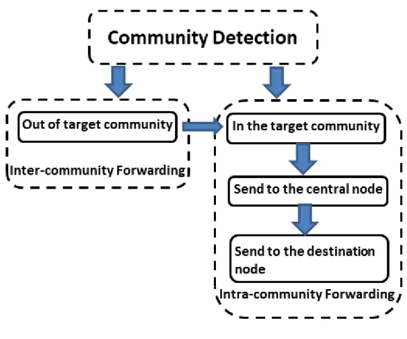
Many routing protocols are designed with the concept of social communities recently. This feature could effectively help the node predict the chance of encounter and select the appropriate relay node [64]. Communities usually require the support of community detection algorithms. Different communities may coincide with each other in the process of node movement. Social-awareness routing protocols usually divides the data forwarding process into two stages: the inter-community data forwarding stage and the intra-community data forwarding stage, as shown in Figure 2-5.
20
Figure 2-5 Data forwarding process of the social-awareness routing protocol.
When the source node and the target node are not in the same community, a relay node is needed to forward the message to the community where the target node is located. After the message is forwarded to the target community, the relay node will forward the message to the target node according to the specified strategy. The message forwarding strategy within a community is usually different from the message forwarding strategy between communities. For the social-awareness routing protocol, community detection and construction algorithms are very important. There are three typical algorithms: SIMPLE [65], K-Clique [66], and MODULARITY [67]. Meanwhile, the Bubble Rap routing algorithm based on the K-Clique algorithm is proposed [68]. The protocol generates social contact graphs based on historical encounters to discover communities. Bubble Rap builds and maintains the node ranking table in the network. When data is forwarded, it is first transmitted according to the global ranking until it has arrived at the community that the destination node is located. Finally, the local ranking is used to find the destination node in the community.
21
Bulut et al. identify social connections between nodes based on direct and indirect friend connections between nodes and establish friend-based communities [69]. They believe that close friend contact has three characteristics: high contact frequency, long contact time, and regularity. So, they defined social pressure metrics (SPM) and conditional social pressure metrics (conditional SPM) to represent direct and indirect friend contact, respectively. The values of these two indicators are maintained by analyzing the historical contact records. The node where the direct or indirect friend contact exceeds the threshold constitutes the friend-based community. Moreover, in order to show the difference in time, different groups of friends were established for each node at different times of the day. When data forwarding starts, the node with strong connections among friends in the destination community will be selected as the next forwarding node.
Zhou et al. found that the habitual movement of nodes helped to reduce the average communication delay [70]. The behavior deviating from custom will seriously affect the performance of routing. They propose a DR routing protocol that can handle deviant behavior. The protocol divides the network into several adjacent social clusters according to the characteristics of clustering. When the data is forwarded, one copy of the message is delivered for each cluster. In this way, the effect of deviation behavior on routing performance is weakened.
Besides, many studies consider the relationship between communities and specify the data forwarding strategy between communities. The LocalCom protocol [71] uses information such as historical meeting frequencies, meeting lengths, and separation cycles, to define an indicator called “Similarity” and building up Neighboring Graph based on this indicator. Distributed discovery communities based on the Neighboring Graph and Similarity. LocalCom has also developed different strategies for inter-community and intra-community data forwarding. This protocol sets the node that has direct friend contact between the communities as a gate node. Static pre-pruning and Dynamic pruning are used to select forwarding nodes from gateway nodes based on the intermediate number centrality to complete forwarding among communities. In the community, a more suitable relay node is selected by comparing the similarity value.
Xiao et al. proposed a distributed community-based routing protocol [72]. In this paper, the community frequently visited by nodes is named “Home” and the home-aware community
22
model is established. The shortest expected delay for each “Home” provides the basis for routing selection in the extended diagram. Besides, the algorithm extends the concept of centrality to all network nodes.
2.5 Buffer management in VDTN
This section will summarize the recent research work on buffer management in the DTN field. Buffer management is generally based on a certain routing algorithm. The effect of adopting the same buffer management policy will be different depending on different routing algorithms. This section summarizes the main buffer management algorithms in DTNs. The purpose of buffer management is to improve the network performance of routing protocols. The causes and effects of congestion in the traditional Internet can be summarized as follows: congestion caused by regular message transfer; message sharding transmission results in shards that cannot be sent simultaneously; the accumulation of redundant messages, etc. The main effects on network performance are packet loss, increased overhead and energy consumption, an increase in message delivery delay, reduction in the successful delivery rate of messages.
Based on the unique application background of DTN and referring to the traditional network, the thesis proposes that when new messages arrive, the node has remaining cache space that cannot meet the needs of new messages and is forced to take the operation of dropping messages due to insufficient storage as the DTN node is congested define standards. Most DTN applications are in extreme environments such as deep space, deep sea, remote areas, and the wild, which inevitably have different deployment requirements and restrictions from the traditional Internet. In these special application environments, since communication nodes with large-capacity storage devices are generally unable to be deployed, there are often limited storage resources and tight competition. At the same time, after deploying DTN in these environments, its communication performance requirements are not the same as those of the traditional Internet.
The algorithm design often takes the message delivery rate as an important evaluation index due to the unique network topology and intermittent connectivity of nodes in the DTN. Moreover, network congestion, as an important influencing factor, is also attracting more and
23
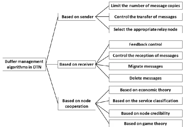
more attention. How to use limited network storage resources reasonably is related to network performance in special application environments. The classification and introduction of DTN buffer management algorithms are shown in Figure 2-6.
Figure 2-6 DTN buffer management algorithm classification.
2.5.1 Buffer management based on the sender
The buffer management algorithm based on the sender is controlled mainly from the perspective of the sender to avoid the unreasonable occupation of the cache space of other nodes. This kind of buffer management algorithm is generally accomplished by restricting the message replicas in the network, controlling sending messages, and selecting appropriate relay nodes.
2.5.1.1 Limit the number of message copies
24
will quickly consume the limited network storage resources and inevitably cause congestion. It is necessary to take effective measures to control the unrestricted spread of message copy to suppress network congestion.
In order to overcome the network congestion caused by the routing algorithm spreading messages arbitrarily, the simplest method is to add control of the number of message copies during the flood routing algorithm execution [73]. Nodes control the spread of a message copy by comparing nodes encountered with this message to the total number of nodes encountered over a period of time. The message copy will immediately be cleared to avoid being forwarded further and wasting network storage and communication resources after the transmission. Other nodes perform the cleanup of the delivered copy immediately by publishing the message delivery confirmation table when nodes meet.
SMART [74] groups frequently encountered nodes in a partner group. In the first phase, the source node distributes a fixed number of message copies in the network in a binary spray mode; in the second phase, when a message copy is transferred to the destination node’s partner group, the node increases the number of message copies, and only in the group continue to execute the binary spray until the message delivered to the destination node. In this way, SMART reduces the total number of message copies required for successful delivery and relieves congestion. A-SMART [75] is an improved SMART algorithm. In the first phase, the message is not sprayed. After the message is transferred to the destination node partner group according to the minimum number of hops, the same delivery as SMART is performed in the second phase.
RR [76] is based on the idea that more message copies could cause more network congestion. By observing local network congestion, i.e., updating the message copy threshold according to the proportion of the delete operation in the normal relay operation. The worsening of network congestion is avoided.
DCCR [77] uses dynamically adjusting the threshold to avoid congestion. The threshold calculated by collecting the cache usage rate of neighbor nodes, the node divides the congestion of the surrounding network into mild, moderate, and severe (prohibit message copying, and perform a history based on the probability of encountering routing), congestion (moving the longest-lived message to the neighbor node, letting it execute the direct delivery strategy, and no longer transfer the message).
25
2.5.1.2 Control the transfer of messages
TBCC [78] sets a fixed token in the network for strictly controlling nodes to send and receive messages according to network storage resources. The initial token of each node is the same. When a message needs to be forwarded, the token needs to be used, and the receiver receives the token. In this way, when a node token is used up, no more messages can be sent. Only after helping other nodes to transfer messages to harvest tokens or borrowing tokens from neighbors can they send messages again. When a message is deleted due to congestion, expiration of lifetime, or arrival at the destination, the token of the corresponding node is added. This strategy strictly controls network congestion.
Lakkakorpi et al. [79] broadcast congestion signals to the surrounding nodes when the uplink storage was about to run out. In this way, the current node no longer communicates with surrounding nodes until the congestion signal is removed and resumes the message transmission.
Consider the impact of message retention time on network congestion. If nodes transmit incomplete messages in the limited connecting time, too many message fragments will be scattered in the network and occupy the network storage resources for a long time. This affects the destination node to receive the message once, increases the message delivery delay, and easily triggers network congestion. To avoid the situation mentioned above, Al-Siyabi et al. proposed an access control (AC) [80], which first relays messages that can be transmitted all at once within a limited time of connection. If the remaining connectivity time can only transmit part of the message, the remaining message fragments will be forwarded first the next time there is a connectivity opportunity.
The FRMM [81] uses the Jains equity index and allocates different connection bandwidth for each node according to its weight, which plays a certain role in reasonably allocating resources and controlling congestion.
According to the local flow at each node and the remaining cache space of the relay node, the LFC [82] adjusts the data flow at each node to control the storage overflow of the relay node, the saturation of the transmission link, and the increased burden of useless retransmission to the network. This algorithm is mainly proposed for interplanetary networks.
26
Wittie et al. [83] set up fixed base station nodes with low communication bandwidth and long communication distance in mobile nodes with a relatively fixed movement range of high communication bandwidth and short communication distance to complete information collection of each node and message status in the network, so as to centrally control network resources and shunt, and control congestion of each node.
2.5.1.3 Select the appropriate relay node
Sometimes, congestion control needs to consider message generation and transmission and select the appropriate relay node to complete the message delivery. Many factors need to be considered in choosing a suitable message relay node to get an optimal relay operation, which can ensure the successful delivery of messages and effectively control network congestion. In the algorithm that only uses a single factor to select appropriate relay nodes, MobySpace [56] selects nodes with a similar movement model of destination nodes as the relay nodes. There are various combinations of specific parameters to determine the appropriate node in careful consideration of many factors. In terms of only considering the node itself and local static attributes of the network, CAFE [84] exchanges state information and historical encounter records of each node when it meets, and maintains two management modes. Congestion management is concerned with the availability of neighbor nodes, such as remaining storage and average latency. Contact management focuses on previous contacts (duration, frequency, last encounter time) and message forwarding between neighbor nodes and other nodes. Combine these two kinds of information to select the appropriate relay node Radenkovic et al. [85] integrate node sociality, node resources (remaining storage, delivery delay, and historical congestion rate), and local network characteristics (the overall storage remaining status in the network, the possible increased delivery delay and congestion rate) guide message transfer to avoid hotspot areas with high delivery probability but prone to congestion. While increasing the number of hops required for successful delivery, it guarantees the message delivery rate and avoids congestion.
Khuu et al. [86] take into account the number of hops, the connection rate, and the interference from other nodes in the message delivery process (density of neighbor nodes) to jointly determine the effectiveness of the available link as an assessment of congestion
27
standard to select the appropriate relay node for message delivery.
GRCCM [87] prevents nodes from over-selecting nodes with high delivery capabilities (such as base stations) to relay messages, resulting in node congestion and network performance degradation. The node’s remaining buffer space, the number of neighbors, the transmission bandwidth, and the game theory is used to determine the proportion of messages distributed to high delivery capability nodes and low capability nodes (regular vehicles) to achieve maximum delivery performance. While using high-capacity nodes to assist delivery to maximize network performance, rational use of low-capability nodes to assist delivery can avoid the congestion of high-capability nodes.
DFR [88] considers dynamic factors such as node movement in selecting relay nodes. When the nodes meet, compare the list of node position coordinates they carry and decide whether to update the node position information according to the node coordinate age index. The relay node selection is based on whether the azimuth angle between nodes is less than the threshold, and the relative movement trend of the two nodes. At the same time, it is also based on the density of messages that have been disseminated, the delivery possibility, and TTL to determine which types of messages to transfer or delete can improve the network performance. Furthermore, use ACK to delete the delivered message copy in time.
2.5.2 Buffer management based on the receiver
In the buffer management algorithm based on the receiver, the node buffer is allocated from the perspective of the receiver to effectively reduce its storage burden and alleviate and suppress network congestion. This kind of buffer management is generally accomplished through feedback control, control the reception of messages, migrate messages, and delete messages.
2.5.2.1 Feedback control
Due to the stable end-to-end connection of the traditional Internet, the method of controlling congestion from the global network is generally adopted. The purpose of eliminating congestion is achieved by establishing a global feedback control system [89] and using the Nyquist criterion [90]. Due to the unique communication characteristics of DTN, coupled
28
with the intermittency of DTN connection and the unpredictability of node encounter time, feedback generally has a severe lag, which cannot sufficiently reflect the real-time condition of network congestion. The lagging congestion control will also cause a large jitter in the message sending rate and instability of the DTN data transmission rate.
Godfrey et al. [91] directly used feedback to adjust the message sending rate. When the node gets the feedback that the message is lost, it directly rolls back the message sending rate to the rate of the last successful message delivery. Cen et al. [92] used the TFRC method [93] in the traditional Internet to pass an acknowledgment between the destination node to the source node to adjust the message sending rate of the source node. Johari et al. [94] proposed a buffer management method to stabilize the network transmission performance by analyzing the relationship between message queuing delay, propagation delay, and congestion obtained from feedback. ATP [95] is based on this principle that the message delivery delay can reflect the characteristics of network congestion, and the message delivery delay is fed back to the source to adjust the message sending rate of the source and control congestion.
2.5.2.2 Control the reception of messages
From the perspective of using the limited storage resources of nodes efficiently, C2AM [96] considers the encounter interval between nodes, the number of messages waiting to be transmitted in the node, and the transmission bandwidth, to estimates the time that the message stays in the node cache. Try to avoid receiving large messages that may remain in storage for a long time or messages with a short lifetime. This method can ensure that the node helps transfer multiple messages as much as possible in a short time. At the same time, it also avoids that the message is deleted due to the end of its lifetime before successfully delivered and the waste of storage resources used along the process.
Zhang et al. used the revenue principle in ref [97], tended to receive more high-weight and easy-to-deliver messages, and increased the delivery rate as revenue. At the same time, the storage cost paid for receiving low-weight and difficult-to-deliver messages, resulting in no remaining storage for nodes to receive higher priority messages in the later time, is taken as the expected overhead.