STABILITY EVALUATION OF AN UNDERGROUND QUARRY IN OYA
Tumelo K.M Dintwe
1*, Takafumi Seiki
2, Shizuo Noguchi
31, 2
Utsunomiya University, Graduate school of Engineering, 7-1-2 Yoto 321-8585, Utsunomiya
3Kawasaki Geological Engineering Co. Ltd, Oya observation centre, Utsunomiya
*Corresponding author
:
mt166474@cc.utsunomiya-u.ac.jpABSTRACT
In underground mining and civil structures, stability is vital for safety and functionality of the space. It is therefore essential to evaluate and predict potential failures and suggest possible countermeasures. This paper presents findings of a study conducted to assess the stability of Oya Underground Quarry in Japan that uses room and pillar mining method, using the 3-Dimensional numerical modelling Finite Difference program (Flac3D). The analysis took into consideration effects of the
large persistent mapped-out joints in the quarry cross-cutting pillars; this was necessary as joints are zones of weakness in rocks and they are known to reduce the strength of pillars consequently affecting the stability of the whole underground opening. With frequent earthquakes occurring in the study region, seismic performance and response of the underground quarry were as well carried out. Simulation results revealed that in both static and after dynamic loading, the quarry is relatively stable. However, the presence of joint discontinuities on pillars at particular orientations could significantly reduce the pillar strength.
Keywords, Joints, Oya underground quarry, Pillar strength, seismic response
1 INTRODUCTION
Underground mine stability is a major concern in geotechnical division mainly for the safe working environment in the mine [1]. Stability in the underground space is affected by a couple of factors. In this paper, attention will be limited to discontinuities and dynamic elements. The Oya underground quarry mine, under investigation is an operating room and pillar type, and therefore, it is inevitable not to focus on the pillar stability as a significant consideration. In room and pillar type mines, pillars are accountable for the entire support of the overburden load from the rooftop up to the surface. Additionally, pillars ought to be firm through the mining process and in some cases even for post-mining activities [1-3]. Discontinuities in general, are zones of weakness, thus, if present in a rock mass or an intact rock, strength is reduced. Discontinuities can cause different types of failures in rock mass depending on their position, orientation and inherent joint properties. In most cases, discontinuities increase instability, they pose great risks when primarily found on the pillars; and could potentially lead to rock fall or overall failure of the underground. On static scenarios, structures may tend to be stable even with the presence of discontinuities. However, in the dynamic conditions such as earthquakes, initiation of structure failure, or/and failure augmentation is likely to occur, especially at the discontinuities. It is for this reason that is necessary for the investigations to put dynamic loading into consideration. The representation of persistent joints on pillars can be performed implicitly or explicitly in numerical programs, and yield relatively accurate behaviour of the rock mass. Still, on the numerical codes, the seismic assessment could be enabled, by configuration to a dynamic mode to get the seismic response of the rock mass. This paper aims to evaluate stability by assessing the discontinuity effects and evaluating the seismic effects on Oya tuff underground quarry with a numerical code Flac3D along with some of the conventional empirical
methods. Figure 1 and 2 are the study sides showing the active quarry in Oya and the subsidence of an abandoned quarry in Oya region. From Fig. 2 it is apparent that the stability assessment for the long-term is crucial for underground quarries
to avoid such sinkholes.
2 GEOLOGY AND GEOTECHNICAL SITE OBSERVATIONS
2.1 Geological setting
Oya underground quarry is located in Oya town Tochigi prefecture north of Tokyo. The region is widely known for its stone mines that have been quarried over 100 years back, and it consists of over 200 underground quarries [4]. The geology is characterized by the mined soft rock known as Oya tuff which is a volcanic rock that has been deposited as rhyolitic ash in the Miceone epoch around the Aquitanian stage (20Ma) [5,6]. The stratigraphic sequence of Oya consists of the basal sandstone and chert formations of the Paleozoic era, overlain by the Oya tuff which is divided into three horizons: upper, middle and lower based on the strength [5]. Oya underground quarries targets and mines out the middle part which offers the high-quality stone.
2.2 Stability assessment
We acknowledge that little research has been done on the study to understand the stability of the quarries with corroboration of engineering and scientific methods at Oya underground quarries. Moreover, discontinuities and seismic responses were not taken into consideration. Previously, Seiki [6] performed numerical simulations on a long wall type quarry located nearby the room and pillar quarry and concluded the underground space to be safe based on the static and dynamic state simulations and field observations. Currently, workers in the quarry use a modified checklist to assess the conditions of the walls and the pillars [6]. In most cases recommendation to install systems or backfill is based on judgments and observation of the workers. Generally, when assessing underground spaces particularly room and pillar, the initial stability evaluation usually addresses the following listed components for pillar supported underground spaces.
1. The pillar stress levels 2. Roof and floor behaviour
3. Pillar condition, shape, and volume (geometry) 4. Extraction ratio
5. Discontinuities 6. Dynamic loading
The above-stated stability affecting components are discussed in detail by various authors [7-9]. The stress levels can be estimated using the tributary area method which gives a conservative stress estimate that is related to the extraction ratio. The relation was illustrated by Brady [7] and shown that for a small increment in exaction ratio, high-stress levels are induced. Roof walls are above the pathways that allow access to the operation areas, and for that, it has to be stable throughout the mining life for safe access. For obtaining stable roofs, the process starts with the design up to monitoring and maintenance. The design prominently relies on the practical experience and success of the already existing layouts [8]. However, the condition of roofs is controlled by overburden, horizontal stress and the intrinsic mechanical properties [9]. The latter allows for empirical methods such as rock mass classification systems to be used for early assessment and even indicate support for low rating span walls. The mentioned empirical practices are found to be inadequate and are supplemented by numerical methods that account for relatively all the stability affecting components. Comprehensive numerical simulations carried out in other studies, point out the importance of pillar width to height w/h ratio to the behaviour of pillar stiffness and strength [1, 7];. It is known in theory and practice that when w/h reduces stress levels increase. Also, it is the intrinsic rock properties that mainly control the failure or load carrying capacity at low w/h l [1].
2.3 Seismic
Various cases around the world of earthquake effects on underground space are discussed by Bäckblom, [10], the mentioned cases include tunnels mines and repository spaces. As it could be anticipated, from the stated citations of seismic events [10], Japan recorded more cases than any other countries under investigation, and the majority of the cases were effects on tunnels. For detailed seismic damage on underground mines in Japan, Aydan [4] assessed the destruction of this structures after the 2011 great earthquake. From the list of the damaged structures research, one was the collapse of the semi-underground quarry located in Oya in the neighbourhood of the presently studied quarry. Oya underground quarries are considered shallow structures as mining depths currently are less than 100m. Shallow structures are more susceptible to seismic damage than deep underground openings [10-12], and the surface ground motions are known to be much more robust than the subsurface motions. A recent study by Seiki [6] on seismic responses of longwall type quarry 2km away from the current study area, has shown that increase in wave velocities results in high strain levels on the roofs walls. Pillars experience dynamic loading during earthquakes, and in response, failure may occur as the pillar strength is reduced. Likewise, roof and floor tend to be prone to failure under dynamic conditions. The ground motion can cause the development of fractures as cracking on the roof, and spalling takes place leading to rock falls. The estimation of the dynamic loads on both roofs and pillars can be given using the proposed analytical equations by Aydan [12]. In Oya room and pillar quarry, there are some fractures on side walls and pillars, and the preassumption is that some developed during the great 2011 earthquake.
2.4 Joint discontinuities
Presence of joints in a rock medium reduces the strength of the rock and rock mass. For modelling; joint constitutive models are an option to represent joint implicitly in continuum numerical models [13-16]. Rafeh et al. [13] developed a yield criterion that demonstrates the joint effect on the strength of the chalk material. The orientation (dip angle) of the of the weak plane shown to dictate the strength, stress distribution within the rock [13] and corresponding results have been previously mentioned with a different proposed constitutive model [14]. All works mentioned above suggesting constitutive models compared the proposed models with the built-in models of Flac3D and clear fitting correlations were
achieved. Their goal was to improve on ubiquitous joint model limitations and be capable of accounting for more than a single joint set, yet producing the same output as the ubiquitous model. The Flac3D ubiquitous model follows the analytical
theorem developed by Jaeger [15] that represent a single joint set. Both Jaeger model and Flac3D ubiquitous joint model
result in a U-shaped strength curve for varying joint orientations [16]. In Oya quarry, persistent joint discontinuities that are observed, have not been included in the past investigations at the design stage. The average joint spacing was more than 12m, with persistent traces that cross cut the pillar and reach the roof walls and at an average of dips of 78º, see Fig 5(c). The site observations indicate that these joints do not appear to be affecting stability. Although it seems stable, it will be cautious to say their influence is not yet pronounced. Additionally, almost in all joint discontinuities mapped, there is water seepage (damp), and wall rock alteration of about 5cm away from the joint plane.
3 METHODOLOGY
The whole underground space was set up using Flac3D program, from the vertical shaft and to all other horizontal openings.
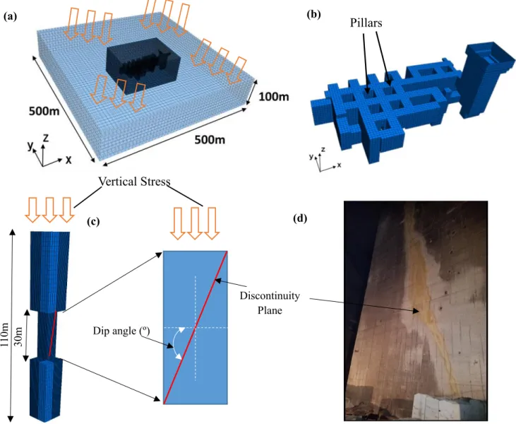
The finite difference mesh has dimensions of 500×500×100 m (length × width × height) see Fig. 3(a) and the rock property parameters used were collected from the laboratory experiments and are shown in Table 1. Simulation model adopted the elastic-perfect plastic constitutive model for the whole rock mass using the Mohr-Coulomb criterion. Figure 3(b) shows the excavated zones. The bottom of the model has a rigid boundary condition, while the sides are constrained by roller boundaries that enable sliding; later on, in the dynamic state, roller boundaries were replaced by viscous boundary conditions and the bottom freed. Oya tuff is generally massive, and the rock mass in the underground quarry has few joints. However, most of these joints are significant and persistent and readily visible cross-cutting pillars. Characterized by a single dominant joint set with steep dip angles and large spacing, homogeneity was assumed for the rock mass.
Firstly, to determine the ultimate pillar strength, a single pillar model was developed as shown in Fig. 3(c) according to the quarry extraction ratio which results in a w/h of 0.3 at 10m width and subsequently subjecting the top of the model to vertical stress that is under servo control. As a result of symmetry, a quarter of the model was used and this greatly reduced
Table.1 Mechanical properties of Oya tuff and joint Bulk modulus
(GPa
Shear modulus (GPa)
Cohesion (MPa) Friction angle (º)
Tension strength (Pa) Rock 1.38 0.91 2.1 30 1.08×10⁶
computational. The actual in situ normal stress states among the individual pillars in the quarry are herein, estimated using the tributary area concept then model was run to equilibrium. The tributary area method was ideal in this case due to the regular layout of the mine, with the assumption that the vertical load will be equally distributed on pillars. It should be noted that in this study only the square pillars in the quarry are considered. The vertical load on the pillar was then increased to more than the in-situ state, to induce complete failure of the pillar. Since Oya tuff follows the strain softening path, the strain softening constitutive model has been chosen for the single pillar to understand the post-failure behaviour further. Moreover, it is widely putative that the strain softening constitutive law better represents the post pillar behaviour [1]. Then
vertical stress and displacement (strain) were continuously monitored to have a stress-strain curve. To evaluate the joint effect, joints of various attitudes were embedded in the single pillar model with the Ubiquitous joint model option. The dip angle was varied from 0 to 90 degrees at 10-degree interval; this enabled the pillar strength monitoring with the presence of a single dominant joint set at different dip angles. The idea here is to investigate the effect of the geometrical property of the joint (dip angle) on the overall strength of the pillar and to achieve this; all other inherent joint properties were held constant and only dip angle varied. Figure 3(c) shows the variation of the joint orientation within the pillar model and Fig. 3(d) show the actual field steep joint cross-cutting the joint.
In the dynamic configuration, the input dynamic ground motion prescribed at the whole quarry model bottom for base shaking, it is a past earthquake data recorded at a nearby monitoring station. After the seismic excitation, the yield state was observed and compared with the static yield state. The maximum principal stress is let to act in the same direction as the gravity as shown in Fig. 5(a) with arrows. The global overburden pressure value exerted here is estimated around 0.65MPa at a depth of 40meters around the roof walls of the quarry.
(c)
(b)
Figure 3. (a) 3D Model setup of Oya underground quarry; (b) excavated region; (c) Pillar model; (d)Large steep joint
discontinuity cross cutting the pillar in the quarry
(a) Discontinuity Plane Dip angle (º) 30m 110m (d)
Pillars
Vertical Stress
(c)4 RESULTS AND DISCUSSION
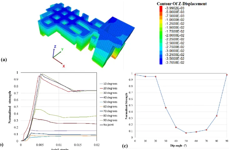
After applying the vertical stress according to the overburden depth of 40m acting on the quarry with the total base depth of 80m shown in Fig. 4(a), there was further subsidence change observed around the roof of about 3.7 cm. This displacement in the vertical direction is bound to occur owing to the stress redistribution after excavation. Nonetheless, the magnitude of this displacement is regarded to be within safe limits and negligible. The distribution of the maximum displacement decreases from the roof down to the floor of the quarry, with a maximum and lowest displacement of 3.7 cm and 3 mm respectively on the quarry model. Ultimate single pillar strength was established, subsequently with that of the pillar with a joint set of various dip angles present. The inclusion of joints reveals possible adverse effects on the pillar. Stress-strain response of the pillar with and without joint is shown in Fig 4b The results in Fig. 4c shows that dip angles between 50 and 60 would reduce the strength of the pillar by 92%; this observation is in good agreement with the angle calculated based on the Mohr-Coulomb criterion of 57 degrees. The least strength reduction by the 0º and 90º is the result of the rock failure not being governed by the joint itself; rather it is mainly influenced by the intact rock failure within the rock mass matrix [14-16]. Figure 5 illustrates the dynamic state, which simulation reveals the possibility of the roof and top shaft walls failure and, whereas static conditions showed yielding onshaft walls only. The detected failure around the
Figure 4.a) Displacement contours, b) stress strain response curve, c) Dip of joints against pillar strength (a)
(b) (c)
shaft opening is disregarded, as the reinforced concrete is already installed for support. It should be noted that the seismic data used for the dynamic condition is one direction (1D). Therefore, the response may be taken to be conservative. Then again, the wave was directly induced at the bottom of the model with data recorded on at the ground surface, and this represents the worst case scenario since the ground motions are usually amplified and much larger than motions at the subsurface.
5 CONCLUSION
The conducted study shows that the inclined joint discontinuities have a significant effect on the overall pillar strength, the numerical analyses showed that discontinuities could reduce the strength by up to 92%. The orthogonal and parallel discontinuity dip angles with respect to the maximum principal stress have much less effect on the pillar strength. The ubiquitous joint model relatively gives the real reflection of the pillar with the joint; however the results ought to be validated by the ongoing laboratory experiments, and ideally, the joints in rocks will be better represented if discretely modelled in discontinuum numerical simulations. Also, the post-failure behaviour has to calibrated according to experiments data, and perform the downgrading procedure. Despite the limitations, the results and more simulations to come would aid in quantifying the factor of safety of the pillars with joints.
For the seismic response, simulation of the dynamic state indicate chances of roof failure. The roof walls are more prone to seismic damage than the pillars and undergo tension failure. Apart, from the small roof area, the rest of the quarry appears to be stable except the vertical shaft opening, in which it is already reinforced, but the concrete reinforcement was excluded in the numerical model. Further studies on the seismic characterisation are ongoing, as well as the applicability of backfill as future support mechanisms for post-mining.
Reference
[1] A. Mortazaria, F. P. Hassani and M. Shabaani, “A numerical investigation of rock pillar failure mechanisms in underground openings,” Computers and Geotechnics, pp. 691-697, 2009.
[2] J. ZHAOU, X.-b. LI, X.-z. SHI, W. WEI and B.-b. WU, “Predicting pillar stability for underground mine using Fisher discriminant analysis and SVM methods,” Transactions of Nonferrous Metals Society of China, pp. 2734-2743, 2011.
[3] Hyuing-Sik, Y. Hyuing-Sik, K. Won-Beom and M. A. Ali, “Perfomance of pillar design in underground stone mines that include discontinuities,” Geosystem Engineering, pp. 187-194, 2012.
[4] O. Aydan, “Crustal stress changes and characteristics of damageto geo-engineering structures induced by the Great East Japan Earthquake of 2011,” Bull Eng Geol Environ (2015) 74:1057–1070, p. 1064, 2014.
[5] T. Seiki , J. Nishi and Y. Nishida, “Renovation Challenge of Underground Quarries for Oya tuff,” in 11th ACCUS conference: Underground Space: Expanding the Frontiers, 2007.
[6] T. Seiki, T. Ishii, K. Takashi, S. Noghuchi and T. Ohmura, “Seismic response of numerical analysis and field measurement in Oya tuff qurry,” Eurock, p. 8p, 2016.
[7] B. H. G. Brady and E. T. Brown, Rock Mechanics For underground Mining, third ed., Dordrecht: Kluwer Academic Publishers, 2004, pp. 375-407.
[8] R. Zipf, “TOWARD PILLAR DESIGN TO PREVENT COLLAPSE OF ROOM-AND-PILLAR MINES,” 108th Annual Exhibit and Meeting, Society for Mining and Metallurgy and Exploration, p. 11p, 2001.
[9] J. Kortnik, “OPTIMIZATION OF THE HIGH SAFETY PILLARS FOR THE UNDERGROUND EXCAVATION OF NATURAL STONE BLOCKS,” Acta Geotechnica Slovenica, pp. 37-41, 2009.
[10] G. Bäckblom, C. R. Munier and S. K. AB, “Effects of earthquakes on the deep repository for spent fuel in Sweden based on case studies and preliminary model results,” Stockholm, 2001.
[11] W. Wang, T. Wang, . J. J. Su, C. H. Lin, C. R. Seng and T. H. Huang, “Assessment of damage in mountain tunnels due to the Taiwan Chi-Chi Earthquake,” Tunnelling and Underground Space Technology, pp. 133-150, 2001.
[12] O. Aydan, Y. Ohta, M. Genis, N. Tokashiki and K. Ohkubo, “Response and Stability of Underground Structures in Rock Mass during Earthquakes,” Rock Mech Rock Eng, 2010.
[13] F. Rafeh, H. Mroueh and S. Burlon, “Accounting for joints effect on the failure mechanisms of shallow underground chalk quarries,” Computers and Geotecnics, pp. 247-261, 2015.
[14] A. Agharazi, C. D. Martin and D. D. Tannant, “Implementation of an equivalent continuum constitutive model for rock masses with systematic joint sets in FLAC3D,” Continuum and Distinct Element Numerical Modeling in Geomechanics, pp. 1-9, 2011.
[15] J. C. Jaeger, “Shear failure of anisotropic rocks,” Geol Mag 97, pp. 65-72, 1960.
[16] B. L. Sainsbury and D. P. Sainsbury, “Practical Use of the Ubiquitous-Joint Constitutive Model for the Simulation of Anisotropic Rock Masses,” Rock Mech Rock Eng, pp. 1507-1528, 2017.
![Figure 1. Oya underground quarry Figure 2. Collapse of underground quarry [5]](https://thumb-ap.123doks.com/thumbv2/123deta/8157106.1271247/2.892.451.753.86.334/figure-oya-underground-quarry-figure-collapse-underground-quarry.webp)