1. Introduction
In Japan, the phenomenon called "the dislike of science," which has been observed for over 10 years, has become a social problem. Understanding this phenomenon and countering it has been approached from various points of view. We tried to address the problem of "the dislike of science" by going back to its origins. To attack the origins of the problem we felt it necessary to develop teaching materials that provide direct experience in science. To gain some perspective we go back to the teaching maxim that “What I hear I forget. What I see remember. What I do I understand.” And, we note that it is important for each person to experience and understand the information processing process associated with learning and understanding, that is, placing what is learned in one experiment into their general body of knowledge.
In the learning process it is important to understand the significance of and learn how to handle (learn from) cognitive disharmony. There are three types of cognitively disharmony;
"lack of coordination," "perplexity" and "surprise". "Surprise" occurs when an experiment produces a result which contradicts known knowledge. "Perplexity" occurs when multiple experiments produce seemingly unexpected or inconsistent results. "The lack of coordination" occurs when observation or results are not consistent with other closely allied results.
As one of the countermeasures to the above-mentioned problem, we looked for a teaching experiment with a high probability of producing cognitive disharmony. With this in mind we worked at developing a teaching experiment using two magnets. Though the experiment was simple, it was possible to develop a teaching experiment that induced a large amount of cognitive disharmony.
Coulomb’s law describes the force which arises between two electric charges. Coulomb confirmed by experiment that the nature of the electric force was similar to that between magnetic poles. There are both attractive and repulsive forces, depending on the selection of poles, and in the space between magnetic poles the intensity of that force depends on the inverse of the square of the distance between the magnetic poles. This law also gives the force F which acts between magnetic poles, and it is called Coulomb’s law of magnetism.
The development of teaching material using an experiment to produce
cognitive disharmony
Yuryo S
AKURAI*
It is generally accepted that a repulsive force exists between homopolar magnets. We have, however, encountered a process that is different from the generally accepted repulsive force and use this phenomenon in a teaching experiment that illustrates cognitive disharmony. The repulsive force acts between homopolar magnets only when the difference in magnetic flux density between magnets is roughly equivalent. And this repulsive force changes depending on the distance between the magnets. On the other hand, the force which acts with decreasing distance between magnets, changes from a repulsive force to an attractive one when the difference in magnetic flux density between the magnets is large (one magnet several times stronger than the other). A decrease in the magnetic flux density and reversal of polarity appears in the magnet where the magnetic flux density is lowest. It is clear that the force which acts between magnets changes from repulsion to attraction or vice versa for separations of 1 mm or less. The experimental results confirmed this phenomenon as an effective teaching tool, especially for teaching how to handle cognitive disharmony. Key words: homopolar magnet, magnetization, magnet, repulsive force, attraction force.
*Department of Electrical and Electronic Engineering, Shonan
Institute of Technology, 1-1-25 Tujido-Nishikaigan, Fujisawa, Kanagawa 251-8511, Japan
It is given by equation (1).
F=k・m1m2/r2 (N). (1)
where k is a proportionality constant, m1 and m2 are the
intensities of the magnetic poles (wb), and r is the distance between the magnetic poles.
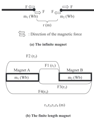
Equation (1) works well for infinitely long magnets with small magnetic poles which can be taken as points (see Fig.1 (a)). Considering a magnetic pole as a point is not practical. However, Coulomb's law is an appropriate approach when magnetism is understood.
Figure 1(b) shows finite length magnets A and B and the forces involved between the two magnets. The Coulomb force consisting of four components is shown as F1 through F4. Equation (2) is used to determine the force acting between magnets of finite length (see Fig.1 (b)).
F=F1+F2+F3+F4 (N). (2)
The following are the fundamental force properties between magnetic poles.
1) Repulsive force acts between magnetic poles of homopolar of N (S) pole and N (S) pole.
2) Suction force acts between opposite magnetic poles, that is, between N (S) pole and S (N) pole.
In the process of developing a teaching experiment we observed the suction force between homopolar magnets. This is a phenomenon which contradicts common sense. It is also one that is of interest to us. This presented us with a situation with considerable "cognitive disharmony." We then asked the question, “Why is this attraction force generated between homopolar magnets?.” This study was carried out in order to answer this question, i.e., resolve the situation of "cognitive disharmony." As a result of experimental examination using various magnets, we observed the attraction force phenomenon associated with magnetization in homopolar magnets.
(a) The infinite magnet
(b) The finite length magnet Fig. 1 The force acting between magnets.
2. Experiments
The sample magnets used in this study are listed in Table I. All the sample magnets are available commercially. Figure 2 is a schematic of the apparatus we used for the experiments. This equipment consists of components to hold the magnets and control the distance between them by changing the position of one of the magnets, etc. An automatic X-Y stage was used for fine control of the distance between magnets. The change in distance was accomplished by the transfer stage. The distance the stage moved was measured using a slide type potentiometer. The large contact of the potentiometer was fixed to the base of the apparatus. The slide contact was fixed in the X-Y stage. The resistance in the potentiometer changed depending on the position of the stage. With current in the potentiometer a change in resistance, equivalent to displacement of the X-Y stage, was measured as a (change in) voltage. This voltage determined the separation of the magnets. The force F in Newtons from the force meter was measured as the distance between the magnets was changed. Recording of the distance and force was done by computer. The forces for distances of less than 1 mm are most interesting. The distribution of magnetic flux density near the magnetic pole was measured using a magnetic flux density measuring instrument.
Fig. 2 A schematic of the experimental equipment.
3. Results and Discussion
The relationship between the force acting between homopolar magnets and the distance between the magnets for all the combinations of samples was examined. The force is based on the magnetic condition. There are two features to the magnetic characteristic curves (force versus separation). Figures 3 and 4 are examples of the characteristic curves between N magnetic poles. Similar characteristics also were
observed between S magnetic poles. The positive (negativity) region of the vertical axis of the graph shows the attraction (repulsion) force.
The characteristic in Fig. 3 is a typical characteristic of the force which acts between homopolar magnets. The characteristic in Fig. 4 graphically shows one object of this study. The characteristic features in this curve show that the type of force which acts between magnets changes depending on the distance between the magnets, i.e., the repulsive force is superposed on the attractive force, when the distances between the magnets is less than several mm. This characteristic appeared, when sample M1 was combined with other samples (M2, M3, M4). These results prove the experimental result (attraction) observed by holding the magnets in both hands. Generally, only the repulsive force as shown in Fig.3 is observed between homopolar magnets.
F(N)
Fig. 3 The relationship between force and distance between homopolar (N pole) magnets (sample M1 and sample M1).
F(N)
Fig. 4 The relationship between force and distance between homopolar (N pole) magnets (sample M1 and sample M3).
Now examine the characteristic shown in Fig.4. Generally, the attraction force is generated, because the synthesis of the magnetic field for other than short distances is easy between different magnetic poles. On the other hand, the repulsive force arises because the synthesis of the magnetic field for very short distances is difficult between homopolar magnets. From this characteristic we can presume the existence of the strange pole phenomenon, i.e., it appears that a partial reversal of magnetic pole for one of the magnets has been generated. The existence of this reversed magnetic pole is established by measuring the magnetic flux density distribution. The magnetic flux density distribution in the magnetic diameter direction after use was measured for all the samples.
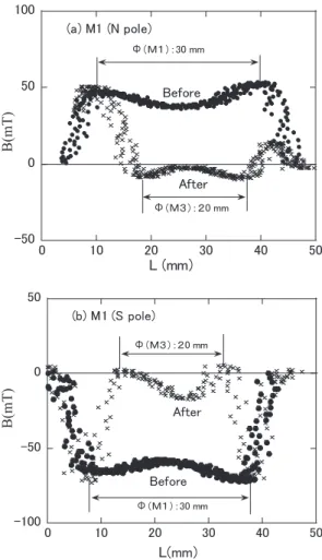
The flux density measurements were different for the characteristic of Fig. 3 and the characteristic of Fig. 4. The change in the magnetic flux density distribution in use and after use is barely noticeable for the characteristic of Fig.3. Examples of flux density measurements are shown in Figs. 5(a) and 5(b). The horizontal axis is the distance L mm in which the sensor was moved (near the surface) in the diameter direction. The vertical axis in the figure is magnetic flux density B mT. The coincidence of the positive (negativity) shows the direction of the magnetic field, i.e., the positive (negativity) shows the N(S) pole. The change in magnetic flux density at about 20 mm (≒M3 diameter Φ) when facing another magnet is large. In the characteristic after use there is a region where the polarity
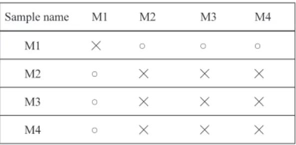
of the flux changes from positive to negative. This shows that a reversal of the magnetic pole was generated at sample M1. This is where the magnetization phenomenon appeared. Table II shows the combinations that produced this magnetization phenomenon. Looking to Table II, the characteristic of Fig.3 appears, when the magnetization phenomenon does not occur. On the other hand, the characteristic of Fig.4 appears when the magnetization does occur.
B(mT)
B(mT)
Fig. 5 Magnetic flux density distribution of (a), the N pole, and (b), the S pole. The magnetic flux density distribution in the magnetic diameter direction after use for all samples when the flux density was measured before use.
The above result shows that the attraction force acted between homopolar magnets appears when this magnetization
phenomenon appears between the magnets. The magnetic moment (direction) of M1 is changed by the magnetic moment of M2, M3 and M4 in which the magnetic force is relatively strong, when they are forcefully brought close to magnet M1, the magnet with the weaker magnetic force. These results appear to clarify the magnetization phenomenon, when the difference in the magnetic flux density between two magnets is big. The magnetization occurred at sample M1, the one with the lower magnetic flux density. This phenomenon is very interesting in magnets, because it was not expected.
The magnetic flux density distribution was measured before and after the experiment of moving the faces close together to confirm our image of what was occurring with the magnets. These measurements showed that the polarity and intensity of the magnetism was dramatically changed in the weakest magnet and this was especially true in the part of the weaker magnet that touched the stronger magnet. The magnetization phenomenon occurred in the weaker magnet when it was forcefully moved close to the stronger magnet (see Figs. 6 (a) and 6 (b)). As shown in Fig. 6 (a), before they come together the magnetic moment is aligned in the magnetization direction. When the magnets are brought close the reversal of the magnetic pole was generated in part of M1, the weaker magnet by the stronger magnet, M3 (see Fig. 6 (b)). The suction force was generated between part of the pole face of sample M1 by the stronger magnet M3. This phenomenon is similar to the phenomenon which occurs when an external magnetic field is applied to a magnetic substance. In this case, sample M1 can be considered the magnetic substance. And the magnetic field of sample M3 can be considered the external magnetic field. A magnetic domain is created when the alignment of magnetic moments is disturbed. The generation of magnetic lines of force decreases when magnetic domains are created, that is, the magnetic flux density is decreased. The magnetic flux density distribution of sample M1 seemed to change in a complicated way because this phenomenon occurred.
(a) The distance between magnetic poles is long
(b) The distance between magnetic poles is short Fig. 6 A schematic of the magnetic moment of samples
M1(B:~ 60 mT) and M3(B: ~280 mT) in the case in which the distance between magnetic pole is (a) long and (b) short.
It is possible to describe the fundamental property operating between magnetic poles taking what we have described above into as account as follows.
1) A repulsive force arises between homopolar magnetic poles, N (S) pole and N (S) pole. However, in the case where the magnetic flux density difference between the magnetic poles is big, a suction force is generated as described above.
2) This suction force is generated between the magnetic monopoles as if the poles were N (S) pole and S (N) pole. The phenomenon observed at this time contradicted common sense, and produced three types of cognitive disharmony: "lack of coordination,” "perplexity" and "surprise." Encountering this phenomenon produced questions and concern. By study and experimentation we answered the questions. In the study of magnets there is a situation where there is a suction between homopolar magnets. Though the study involved a simple experiment we experienced “cognitive disharmony." Though the phenomenon was easily understood by applying knowledge of and experience with magnets it was difficult to understand until the facts in the experiment were clarified. The difficulty in understanding was effective for eventual understanding of the phenomenon.
The effectiveness of the experiment as a teaching tool was confirmed by the above description of the experiment. Most of the 50 students who performed this experiment experienced “cognitive disharmony.” That the students experienced this difficulty and were able to work through the experiment and understand the phenomenon was our aim in developing this experiment. The experiment was highly effective as a learning tool. Also the experiment helped in reducing the general tendency that “science is disliked” among the students. Because of the success of the experiment and the additional benefit of countering the “science is disliked” phenomenon more of these types of experiments should be used in teaching. This is a problem for the future.
4. Conclusion
The development of an experimental teaching tool that induced "cognitive disharmony" and involved "the science is disliked" phenomenon is described. As a result of attempting to produce experimental teaching material using two magnets, we were successful in producing “cognitive disharmony” and confronting the “science is disliked” phenomenon.