INVITED PAPER
Special Section on Enriched MultimediaData Embedding into Characters
Koichi KISE†, Shinichiro OMACHI††, Seiichi UCHIDA†††a), Masakazu IWAMURA†,Senior Members, andMarcus LIWICKI††††,Nonmember
SUMMARY This paper reviews several trials of re-designing conven- tional communication medium, i.e., characters, for enriching their func- tions by using data-embedding techniques. For example, characters are re- designed to have better machine-readability even under various geometric distortions by embedding a geometric invariant into each character image to represent class label of the character. Another example is to embed var- ious information into handwriting trajectory by using a new pen device, called a data-embedding pen. An experimental result showed that we can embed 32-bit information into a handwritten line of 5 cm length by using the pen device. In addition to those applications, we also discuss the rela- tionship between data-embedding and pattern recognition in a theoretical point of view. Several theories tell that if we have appropriate supplemen- tary information by data-embedding, we can enhance pattern recognition performance up to 100%.
key words: data embedding, character recognition, handwriting, supple- mentary information, character design, geometric invariant, pen device
1. Introduction
In the long history of human beings, characters have been the most important medium for human communication. By using characters, human can record, distribute, know, and understand various information with less errors in their com- munication. Even in the Internet era, we are still using char- acters just like thousands of years ago — if fact, now you are reading characters on a paper sheet or a display to know something about enriched multimedia.
From 1929 — the year of the first optical character reader (OCR) patent by Tausheck [1], characters have grad- ually been an important medium for communication be- tween human and computer. If computers can read charac- ters, computers can collect various textual information from books, business documents, handwritten documents, forms, signboards, road signs, posters, etc., and then provide useful services to human by using the information.
Unfortunately, active researches on OCR have revealed gradually that it is not so easy for computers to read char- acters. Recognition of typed (i.e., machine-printed) charac- ters on a scanned business document is still not perfect by
Manuscript received April 7, 2014.
†The authors are with Osaka Prefecture University, Osaka-shi, 599–8531 Japan.
††The author is with Tohoku University, Sendai-shi, 980–8579 Japan.
†††The author is with Kyushu University, Fukuoka-shi, 819–
0395 Japan.
††††The author is with DFKI, Kaiserslautern, Germany.
a) E-mail: [email protected] DOI: 10.1587/transinf.2014MUI0002
various disturbances [2], such as light/heavy print, skew and warp, scanner noise, low resolution, etc. If we want to rec- ognize handwritten words or scene texts [3], [4], we suffer from far lower recognition accuracy. In fact, the best method of the scene text recognition task at ICDAR2013 Robust Reading Competition [5] achieved 82.8% word recognition rate∗and it clearly shows room for improvement.
This paper introduces several trials for achieving better character recognition accuracies by using a totally different approach from the conventional OCR researches. The ap- proach is to re-design character patterns for increasing their
“machine-readability.” An extreme of this approach is to use
“barcode” instead of characters, since barcode is designed as a machine-readable pattern. This extreme is, of course, not our goal because it is not human-readable. Consequently, both of human-readability and machine-readability are nec- essary in the trials∗∗.
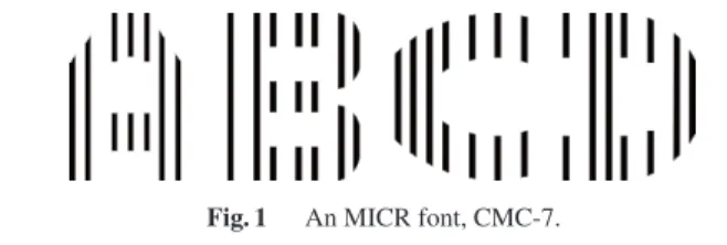
More specifically, the proposed approach is based on embedding some “data” into character patterns. If data is related to any character class information, we can use it for recognizing the character. A classical example of class in- formation embedding into character patterns is MICR font whose example “CMC-7” is shown in Fig. 1. In this font, character class information is embedded into the charac- ter pattern by changing intervals of the vertical line com- ponents. Computer determines its character class by this embedded information, whereas human still determines the class by the entire shape.
It is important to note that the proposed approach of embedding data into character patterns is possible because of the special nature of characters; that is, any charac-
Fig. 1 An MICR font, CMC-7.
∗This accuracy was achieved under the strong assumption that words in scene image are correctly detected and extracted. Scene text detection itself is a very difficult task and the same competition report [5] says the best detection accuracy was still 75.9% in F- score.
∗∗The authors called those proposed patterns as “universal pat- terns” because they are designed to be used by human and com- puter equitably.
Copyright c2015 The Institute of Electronics, Information and Communication Engineers
ter is designable and generatable in an artificial manner.
We, therefore, can re-design characters for better charac- ter recognition accuracy, although we cannot design human faces for better face recognition accuracy. Various fonts are generated everyday by font designers around the world. One font might be designed for better human-readability. An- other font might be designed for providing some impres- sion to readers. In our case, fonts are designed for machine- readability, as well as human-readability.
What data should be embedded? As noted above, it is possible to embed class information (such as “A” and “1”) to enhance recognition accuracy by computer. Another choice is to embed some meta-information. For example, it is pos- sible to embed the font type into characters printed in that font. This also will increase recognition accuracy because OCR can switch its pattern dictionary according to the font type. Another example is to embed URL info to a sequence of characters (i.e., a text), where the URL provides some useful information related to the text. This example reminds us of two-dimensional barcode to link a printed pattern and cyberspace.
On embedding data into characters, several competing requirements exist. The first requirement is robustness on retrieving the embedded data from the character pattern. If we assume a handy camera for capturing the character pat- tern instead of a scanner, robustness to perspective distor- tion (by a non-frontal camera), low resolution, non-uniform lighting condition, etc., is necessary. The second require- ment is higher capacity. Of course, embedding more data is better; however, we need to find the best compromise with the first requirement because generally embedding more data into the same pattern size makes the retrieval fragile.
The third requirement is less damage to character appear- ance. The original appearance should be kept as much as possible and the effect by the embedded data should be less perceptible for better human-readability; however, there is also a trade-off between this requirement and the first re- quirement.
For the first requirement of robustness, one idea is to embed data by using an invariant. For example, if we use a perspective invariant, we can retrieve the embedded data correctly from any camera angle. In the later sections, two embedding methods with a perspective invariant and an affine invariant, respectively, will be shown for more accu- rate scene character recognition via handy camera.
In addition to the above requirements, we need to con- sider the fact that there are two ways of generating charac- ter patterns; that is, machine-printing or handwriting. For machine-printed characters, it is rather easy to embed data because it is realized just by printing data-embedded charac- ter images instead of normal character images. However, for handwritings, we have another requirement of embedding dataalongsidewriting. In other words, since it is unnatural to superimpose data after writing a pattern, writing and em- bedding should be done at the same time. For this additional requirement for handwriting, a special pen device, called a data-embedding pen, is introduced.
The rest of this paper is organized as follows. After a brief overview of related work in Sect. 2, Sect. 3 outlines the basic approach of data embedding into character images.
Then, Sect. 4 introduces two examples of data embedding using a perspective and affine invariants. Section 5 describes the data-embedding pen for embedding data into handwrit- ing trajectory. Finally, in Sect. 6, a theoretical aspect of data- embedding for general pattern recognition problems is dis- cussed.
2. Related Work
Embedding data into character patterns, or enriching char- acter patterns by data-embedding, is a novel trial and thus there are not so many related technologies. The following technologies, however, have some relation to our trial.
OCR/MICR fonts: As shown in Fig. 1, CMC-7 font [6]
is one of the original character patterns where class information is embedded for enhancing machine- readability. A more popular one is so-called “OCR font” where the font shape is controlled for better machine-readability. A weak point of those conven- tional machine-readable fonts is that they were de- signed for scanners or magnetic readers and thus not for cameras. As noted before, characters captured by cameras have difficulties [3], [4], and thus we need more robust machine-readability.
Barcodes: Barcodes are the most popular machine- readable patterns. As discussed already, they are not human-readable and thus we cannot see what a barcode represents. One naive remedy is to put the text that the barcode represents next to the barcode. We, however, are still not sure whether the text and the barcode repre- sent exactly the same information. In addition, putting many barcodes on an object for representing a large amount of information is not welcomed in general be- cause they disturbs appearance of the object.
Watermarks: Watermarks solve the above problem of dis- turbing object appearance because watermarks are in- visible or near-invisible. The proposed approach of embedding data into character images, which are re- viewed in Sects. 3 and 4, is considered as a watermark embedded into character images but differs from the conventional watermarks in the robustness to distor- tion. DataGlyph [7], [8] and the trial in [9] embed data by controlling texture or local shape of the character stroke and thus are considered as watermarks on the stroke area. Since they are fine watermarks and not suitable for camera-based acquisition but for scanner- based.
Digital pens: Many “digital pens” have been developed and their function is usually to capture and record the trajectory of pen-tip movement. One of the most fa- mous digital pens is Anoto†, which captures the dot
†http://www.anoto.com
pattern printed on a paper surface from its pen-tip cam- era and then determines the absolute position of the pen-tip. The data-embedding pen reviewed in Sect. 5 is totally different from those conventional digital pens.
The data-embedding pen can embed arbitrary data dy- namically into the handwritten pattern on a paper and thus its purpose is to enhance the value of handwritten pattern.
3. Data Embedding into Character Images — General Discussion
3.1 How to Embed Data?
Since character patterns are (re-)designable in various ways, the methods of embedding data are also various. For exam- ple, we can control the following factors according to the data to be embedded:
• Character stroke width
• Character stroke texture
• Character stroke shape
• Character decoration
• Color/brightness of stroke
In addition to those factors, we can control background of each character. In fact, the method introduced in Sect. 4.1 uses the entire character area including background, for em- bedding data.
3.2 Embedding Invariant
As already noted in Sect. 1, one important requirement of data embedding is its robustness to various distortions. If we assume that character images will be captured by a cam- era in an unconstrained lighting condition, the embedment should be robust to perspective distortion and non-uniform lighting condition. A simple remedy is to remove such dis- tortions by image processing. For example, there are many methods to estimate perspective distortion [4]. If this es- timation is correct, it is possible to remove the distortion.
However, existence of the many methods ironically suggests that this estimation problem is still not solved completely.
Another, more promising remedy is to use an invariant to those distortions. Aspect ratio is an invariant to scaling.
Moment is an invariant to rotation. Similar to these exam- ples, we can find invariants to a specific geometric distor- tion. In Sect. 4, a perspective invariant, called cross ratio, and an affine invariant, called area ratio, will be introduced for embedding data with enough robustness to perspective and affine distortions, respectively.
3.3 Embedding Class Label
If we want to enhance character recognition accuracy by em- bedding data, the most straightforward way is to embed the class label to each character image. For example, if we em- bed the numbernto character images of the n-th alphabet
(n = 1, . . . ,N), we can recognize the character image per- fectly just by retrieving the embedded number. Accordingly, for the Latin-alphabet, we need to define only a small num- ber of different data values (<100) because Nis small. In contrast, for Chinese/Japanese alphabets, we need to define thousands of different data values.
Even if N is large, embedding the class label is still theoretically possible; however, it is practically difficult. To understand this fact, let us consider a naive case where the data (i.e., the class label) is embedded as a grayscale value (∈[0,255]) of the stroke. Theoretically, the grayscale value is a real number and thus we can have an infinite number of different values. Even in the realistic situation, we have still 256 choices since the value is quantized as an integer in a digital computer system. Unfortunately, however, we can- not assume all of the 256 choices because we have to avoid wrong retrieval due to an error by lighting condition varia- tions. If the grayscale value will change±5 at maximum, the safe setting of grayscale values to be embedded is like 0, 10, 20,. . ., 250 — consequently, the number of data variations is only 26 and insufficient for a largeN. Although this is a naive embedding example, a similar problem will happen to a different embedding scheme.
Fortunately, this problem can be solved by using recog- nition results from a conventional OCR technique. The clue to this solution is the fact that we do not need to discrimi- nate two classes by using the embedded class information if those classes are not confused by OCR. For example, two classes “O” and “I” are very different and thus OCR will not confuse them. (That is, “O” will be never misrecognized as
“I” and vice versa.) Consequently, We can embed the same data value to “I” and “O” and thus decrease the number of data variations. This observation will lead an interesting re- lationship between data-embedding and pattern recognition.
We will review its theoretical investigations in Sect. 6.
4. Two Examples of Data Embedding into Character Images
In this section, we review two examples on embedding data into character images using geometric invariants. Here, data embedded is assumed as class label for enhancing recogni- tion accuracy, although we can embed other data in princi- ple.
4.1 Example 1: Embedding Cross-Ratio
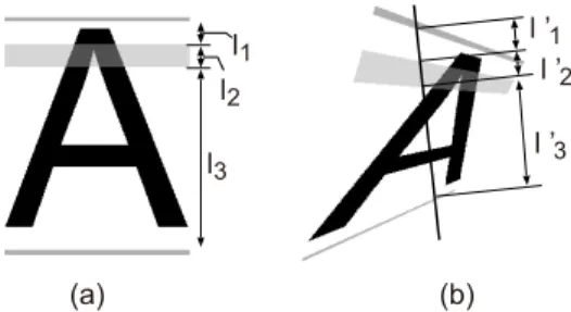
The first example is to embed class information using a per- spective invariant [10]–[12]. A character image is printed with across ratio patternwhich is a set of horizontal stripes, as shown in Fig. 2 (a). The cross ratio calculated from the widths of the stripes represents the class of the character image. If we use different cross ratio values for different classes, character class can be determined just by extracting the cross ratio from the stripes. We, therefore, do not need to apply any OCR technique for recognizing this pattern.
The five horizontal stripes of the cross ratio pattern of
Fig. 2 (a) A character image “A” where its class information is embedded by a cross ratio pattern. (b) Observation line to extract class information.
Fig. 3 Difficulty in detecting the stripe boundaries on an observation line due to fluctuation of gray scale value.
Fig. 2 (a) provides a cross ratioras r=(l1+l2)(l2+l3)
l2(l1+l2+l3) , (1)
wherel1,l2, andl3 are the width of the stripes as shown in Fig. 2 (a). The key idea of this data embedding is that even if a character image undergoes a perspective distortion like Fig. 2 (b), it is still possible to extract the same (i.e., the orig- inal) cross ratio by drawing an observation line which passes across the cross ratio pattern. This is because the cross ratio is a perspective invariant. We can obtain the original cross ratiorby using stripe widthsl1,l2, andl3on the observation line, instead ofl1,l2, andl3 in (1). In other words, we can determine the class of a character image by thisrregard- less of camera angle. It should also be noted thatrwill not change by the slope of the observation line. We, thus, need not to be careful on setting the observation line.
For improving the accuracy on retrieving the cross ra- tio, the following two techniques have been introduced.
FSA-guided optimal detection of stripe boundaries: For extracting the cross ratio by the stripe widths l1,l2, andl3, we need to detect stripe boundaries. Since the grayscale values of the stripes should have a less con- trast originally for making the stripes less conspicu- ous, this detection problem becomes difficult. Figure 3 shows an example of the grayscale values along an ob- servation line on a camera-captured character image with a cross ratio pattern. The change in grayscale val- ues around the stripe boundaries is not always obvious due to various lighting conditions and camera sensor
Fig. 4 Character images with different cross ratio patterns, which are perspective invariant.
Fig. 5 Character images taken from nine different camera angles.
noise. Some simple threshold method, therefore, is in- sufficient to detect the boundaries.
In [12], an optimization-based boundary detection method has been proposed, where the boundary detec- tion problem is formulated as an optimal segmentation problem that assumes that pixels should have similar grayscale values within each segment. This assumption is valid since the grayscale value is originally constant within each stripe (and character stroke). Moreover, the method employs a finite state automaton (FSA) to introduce the rule of valid change in grayscale val- ues along the observation line. A further detail of this method, see [12].
Multiple observation lines: The extracted cross ratio will be still erroneous due to wrong boundary detection re- sults. As an effective remedy, a voting strategy with multiple observation lines is introduced. As noted be- fore, any observation line always provides the same cross ratio. We, therefore, can have the most reliable cross ratio by choosing the most major one among the cross ratios provided at individual observation lines.
An experiment was conducted with 234 character im- ages [12]. The images were created by capturing 26 English capital letters from nine different camera angles. Their av- erage size was approximately 400×300 pixels. As shown in Fig. 4, each character class has a different cross ratio pattern from other classes. Consequently, it is possible to recognize its class just by extracting the cross ratio. Figure 5 shows ex- amples of captured images from the nine angles. The num- ber of observation lines for the majority voting was 81 for each character image.
Among the 234 images, 233 (99.6%=233/234) images provided the correct cross ratio, that is, the correct recogni-
Fig. 6 Examples of generated character images.
tion result. Since the images were taken in wild lighting con- ditions, only 69.2% of observation lines provided the correct cross ratio. However, the majority voting among 81 obser- vation lines canceled the erroneous cross ratios and finally we could get a near-perfect recognition rate of 99.6%.
4.2 Example 2: Embedding Area-Ratio
Although the character images with the cross ratio pattern could achieve near-perfect data retrieval even under perspec- tive distortion as shown in the last section, it appearance is somewhat peculiar. A remedy is to print the cross ratio pat- tern by an invisible ink. This remedy, however, introduces a new requirement that images should be captured under an ultraviolet light.
Is there a more natural embedding method? — An an- swer is to embed data by usingarea ratio[13]. Figure 6 shows its examples, where a shadow is attached to charac- ter strokes in a different color. The area ratio is defined as the ratio between the numbers of pixels in the stroke and the shadow. Data, especially, class information, can be em- bedded into a character by setting the area ratio to a specific value by controlling the area of the shadow. Note that the 26 character images of Fig. 6 (a) (as well as (b)) have 26 differ- ent area ratios (which lies in the range of [0.20,0.45] with the interval of 0.01) and thus, theoretically, their class be recognized by extracting its area ratio.
Since similar shadow decorations are often found in decorated fonts, this is a more natural embedding method than the cross ratio pattern. It should be noted that there are different ways of embedding the area ratios. If a font is de- signed by two colors, it is possible to consider that an area ratio is embedded. For example, we can design a font whose stroke contour is printed in a different color from the stroke.
In this case, a certain area ratio is embedded by controlling the width of the contour.
The area ratio is not a perspective invariant but an affine invariant. It, therefore, cannot be constant under severe per-
Fig. 7 (a) An original character image with area ratio embedment and (b)–(d) its affine-transformed images. The area ratios from them are almost the same.
Table 1 Recognition accuracy (%) achieved by area ratio embedding.
Font Correlation only
Correlation +area ratio
Arial 91.7 94.9
Arial Black 87.2 91.0
Helvetica 91.0 95.5
Times 85.3 92.3
Average 88.8 93.4
spective distortions. However, it is possible to assume rather small perspective distortions, the correct area ratio can be extracted from the character image. In other words, it is pos- sible to approximate small perspective distortions by affine distortions. Figure 7 shows (a) an original character image and (b)-(d) its affine-transformed images. The area ratios ex- tracted from those images were 0.14696, 0.14701, 0.14700, and 0.14697. The difference among the four area ratios is negligible, considering the fact that area ratios of characters in Fig. 6 differs at least 0.01 between different classes.
An experiment was conducted with 624 character im- ages [13]. The images were created by capturing 12 English words (being comprised of 52 characters in total) printed in four different fonts (Arial, Arial Black, Helvetica, and Times) from three different camera angles. (624 equals to 52 characters×4 fonts×3 camera angles.) Their average size was approximately 500×500 pixels.
Although it is theoretically possible to determine the character class only by the extracted area ratio, it is practi- cally difficult by several reasons: (i) the area ratio is not a perspective invariant, (ii) the number of pixels of each color is unstable under a limited image resolution, and (iii) only a single area ratio value can be extracted from a character im- age and thus it is impossible to apply a majority voting strat- egy like the cross ratio patterns. We, therefore, employed a combination strategy with a conventional character recog- nition technique. Roughly speaking, we first determine the rank of each class by the extracted area ratio and also the rank by a correlation-based character similarity. Then, two ranks are combined into a single rank and the top ranked class is determined as the character class. For more details of this recognition scheme, see [13].
Table 1 shows recognition accuracy by the experiment.
The effectiveness of using the embedded class information (i.e., the area ratio) is confirmed at all of the four fonts by comparing accuracies achieved without the class informa- tion. It is noteworthy that decoration (“shadow” in this case)
can enhance recognition accuracy, although decoration is generally treated as a notorious factor of degrading recog- nition accuracy.
5. Data Embedding into Handwriting Trajectory
5.1 Data-Embedding Pen
The approach of embedding data is also applicable to hand- written characters. As noted in Sect. 1, handwritten charac- ter recognition is still a difficult problem in practice. If we can embed class information or other meta-data into hand- written characters, it will help to improve performance of handwritten character recognition or enhance the value of the handwritten characters.
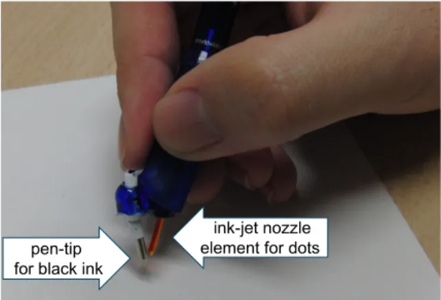
Since each handwritten character is generated by mov- ing a pen, it is necessary to embed information alongside pen movement. For this purpose, we proposed a novel pen device, called adata-embedding pen[14]–[18]. The data- embedding pen has a special ink-jet nozzle element next to the pen-tip, and the nozzle element generate an ink-dot se- quence in addition to a black ink stroke while the pen moves.
Each ink-dot represents an information bit and thus an ink- dot sequence represents a bit-stream of the embedded infor- mation, like a Morse code sequence.
Figure 8 depicts a prototype of the data-embedding pen, and Fig. 9 is an example pattern generated by the proto- type. During the writing, the nozzle produces small yellow ink-dots alongside the handwritten stroke. Yellow is used
Fig. 8 A prototype of the data-embedding pen.
Fig. 9 Ink-dots (yellow) nearby a handwriting stroke (black).
for the ink-dots because it is less visible for human. Invisi- ble ink is a good alternative for making ink-dots invisible.
A closer observation of Fig. 9 will reveal that ink-dots have different lengths. Specifically, short and long dots and a pause are mainly used to form a binary code which rep- resents the data to be embedded. The dot length is con- trolled by using the high-frequency ink injection from the nozzle. Under this high-frequency mode, tiny ink-dots are connected and form a line segment.
For retrieval of the embedded data from a handwrit- ten pattern, we need to estimate the writing order of the pattern; this is because the data was embedded in the or- der of handwriting. This estimation is so-called the stroke recovery problem [19]–[21] and a famous difficult inverse problem. However, if the pattern is not very complex, we still can recover the order correctly by using a sophisticated stroke recovery method like [20]. In addition, as discussed later, we can embed dynamic information representing the writing order into the pattern, and the dynamic information helps to solve the stroke recovery problem.
We can consider various applications of the data- embedding pen by embedding various kinds of information.
For example, embedding writer’s ID, date, and geo-location is simple application. By embedding the price of a product into a check-mark on the surface of the product, the check- mark can be considered as a “handwritten” barcode. If we embed a URL onto a physical paper by a handwritten word, the word becomes a link between physical world and a cy- berspace.
In the beginning of this section, it was said that it is helpful for handwritten character recognition if the class in- formation is embedded into handwriting. This is, however, difficult in practice because it is impossible to determine the class of a character during writing (except for the case where the character to be written is predetermined). In a more feasible scenario is to embed writer’s ID for switch- ing the recognition dictionary already trained for the writer.
Another scenario is to embed dynamic information. While dynamic information helps to recover the writing order for retrieval of embedded data as noted before, it also enhances the accuracy of handwritten character recognition.
5.2 Data Embedding
The basic idea of embedding some data into a handwriting pattern is to represent the data as a binary (0 and 1) sequence and then embed it as a sequence of short dots for “0” and long dots for “1”. In addition, the following techniques are introduced.
Error-tolerant coding: The data is not directly converted into a binary sequence; the data is further converted into a redundant codeword by the Reed-Solomon method to be more robust to error during decoding.
Repetitive embedment: The same data sequence is em- bedded repeatedly until the end of writing. This means that the data will be embedded redundantly and this re-
dundancy helps to cancel retrieval errors.
Special ink dot for synchronization: Synchronization blobs, which are dots longer than the above “1”-dot, are inserted periodically as an anchor to detect missing dots and spurious dots.
Embedding dynamic information: The ink-dot sequence can be used for relaxing the difficulty of the stroke re- covery problem. The idea is the embedment of writing direction by changing the lengths of pauses (gaps) be- fore and after the synchronization blob. If we put a longer pause “before” every synchronization blob and a shorter pause “after” it, we can understand the writing direction by comparing those two pauses neighboring to the synchronization blob.
5.3 Data Retrieval
In order to retrieve the embedded data from a handwrit- ing pattern, we need to perform three steps: (i) Image pro- cessing for identifying the ink-dots as well as the black-ink stroke. (ii) Stroke recovery to re-align the ink-dots in their original order. (iii) the Reed-Solomon method for decoding the embedded data with error correction.
Among the above three steps, the second step is the most difficult. For this step, we use the stroke recovery al- gorithm by [20]. This algorithm starts from representing the target handwritten pattern as a graph whose node corre- sponds to a crossing point or an ending point of the hand- written pattern and edge corresponds to a sub-stroke. Then the algorithm finds the optimal single stroke path by a sim- ple strategy calledbasic trace algorithm(BTA). For the de- tails of the algorithm, see [18] or the original literature [20].
Note that we can incorporate the embedded dynamic infor- mation for enhancing the performance of the stroke recovery algorithm.
5.4 Experiments and Results
Several experiments were conducted mainly for quantify- ing how many information bits can be correctly retrieved through handwritten patterns created by the data-embedding pen [18]. The results of the experiments can be summarized as follows:
• Trials with fifty near-straight lines with 5 cm length have confirmed that we can embed 32-bit information into each line and retrieve it with 100% accuracy.
• If the length becomes 10 cm, 52 bit information was retrieved with 100% accuracy.
• Trials with twelve handwritten “@” marks sized around 3×3 cm have confirmed that we can embed and retrieve 32 bit information with 100% accuracy.
• Trials with twelve cursive handwriting patterns of
“Meyer” sized around 4×3 cm have confirmed that we can embed and retrieve 32 bit information with 100%
accuracy. Nearly same-sized cursive “Clever” patterns also showed the same accuracy.
From the above results, it has been proved that a 5 cm handwriting pattern can be a reliable 32-bit information con- tainer. This suggests our handwriting pattern on a paper can be enriched by the data-embedding pen. If we have a 32- bit information container, it can represents 232 ∼4.3×10⁹ different writer’s IDs and this number is similar to world population. Japanese standard barcode system called JAN- code is comprised of 12 digits (plus one check-sum digit) and it is an information container with far less capacity than a 10 cm handwriting which can represent 252∼4.5×10¹⁵. 6. Theoretical Aspects of Class-Information Embed-
ding
6.1 Supplementary Information
In Sect. 4, we have seen that embedding data into character images helps improve recognition performance. In those tri- als, the embedded data was the class label and thus different data are to be embedded into character images of different classes. On the other hand, as noted in Sect. 3.3, we need not to embedNdifferent class labels for anN-class recognition task, when we make our final class decision by a result from some conventional pattern recognition scheme together with the embed data. For example, we can embed the same data into “O” and “I” because any conventional pattern recogni- tion scheme will never misrecognize them. This example indicates that we can reduce data variations (i.e., the num- ber of bits for representing each data) while guaranteeing perfect or near-perfect classification.
Hereafter, we will use the term supplementary infor- mationwhich is the data embedded into patterns to enhance recognition accuracy, instead of class information. This is because supplementary information does not have a one- to-one correspondence with class label, although it is still related to class labels. As indicated by the above exam- ple, supplementary information should be designed by con- sidering the original recognition performance without sup- plementary information. Roughly speaking, for confusing classes we should not assign confusing supplementary infor- mation values, and for non-confusing classes we can assign even the same supplementary information values.
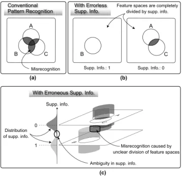
In this section, we review how accurate recognition is achieved with how much supplementary information under two different assumptions that supplementary information is errorless and erroneous, respectively [22]–[24]. We mainly focus on the theoretical inspections here and thus do not on experimental results. Readers who want to know the ex- perimental results, see those literatures. Figure 10 compares pattern recognition models. Figure 10 (a) illustrates the con- ventional pattern recognition that may cause misrecognition due to overlaps of class distributions, which corresponds to the Bayes error. Figure 10 (b) illustrates a case with error- less supplementary information. The errorless supplemen- tary information can completely divide the feature spaces to avoid misrecognition. With more bits of information, more accurate pattern recognition can be realized. A natu-
Fig. 10 Pattern recognition models. (a) Conventional pattern recognition (without supplementary information), (b) With errorless supplementary in- formation, (c) With erroneous supplementary information.
ral question arisen here is “how many bits of supplementary information are required for a 100% recognition rate?” The amount would be a new criterion that measures how diffi- cult the pattern recognition problem to be solved is and can replace the conventional recognition rate. This model holds only if it is guaranteed that supplementary information is obtained without error. Figure 10 (c) illustrates a case with erroneous supplementary information. In this case, the sup- plementary information cannot completely divide the fea- ture space because of its ambiguity. This model is more realistic and general than the errorless one, especially when supplementary information is embedded in the recognition targets (patterns) themselves.
6.2 Errorless Case
Under the assumption that supplementary information is er- rorless, we discuss required amount of the supplementary information to realize a 100% recognition rate. We do not take into account rejection.
As the supplementary information, K kinds of sym- bols are assigned to N classes (K ≤ N). The case of K = N is trivial because a 100% recognition rate is ob- viously achieved without recognition. Thus, the case of K < N is of interest; especially, harmonizing with recog- nition results, how little supplementary information (how smallK) can realize the 100% recognition rate is of inter- est.
For the sake of that, we use a confusion matrix (CM) of a classifier in probabilistic representation as shown in Fig. 11 (a). A CMW is an N×N matrix whose (i,j) ele- ment represents the probability that samples of a true class
Fig. 11 (a) An example of a confusion matrix in probabilistic represen- tation and (b) an assignment of symbols that achieves a 100% recognition rate. Empty elements represent zero-valued. In (b), three symbols are as- signed to realize a 100% recognition rate.
ωiare recognized as those of a classωj, i.e.,P(ωj|ωi). Then, rows ofWare partitioned withKsymbols by assigning one ofKsymbols to each row ofW. A combination of rows to which thek-th symbol is assigned is Let
Hk=
l1, . . . ,l|Hk|
(2) be the rows to which a symbolkis assigned. For example, H1 ={1,2},H2={3,4}andH3={5}in Fig. 11 (b).
As a preparation for the discussion below,Hkis parti- tioned into columns. A combination of elements inHkand in the j-th column is defined as
Bk j={(l,j)|l∈ Hk} (3) For example,B11 ={(1,1),(2,1)},B25 ={(3,5),(4,5)}and B32={(5,2)}in Fig. 11 (b).
With Fig. 11 (a), we discuss the condition that the sup- plementary information should satisfy to realize a 100%
recognition rate. The figure shows that if a recognition re- sult is the class A, the true class can be either the class A, C or E; the true class cannot be determined by the classifier.
If the classifier outputs the class A, it will cause misclassi- fication when the true class is either a class C or E. There- fore, supplementary information is required to distinguish the three classes. This means that at least three symbols are required here. Similarly, if a recognition result is the class B, the true class can be either the class B, D or E. Thus, different three symbols are also required. Consequently, a 100% recognition rate is realized when different three sym- bols are assigned to either “A and B,” “C and D,” and “E”
as in Fig. 11 (b) or “A and D,” “B and C,” and “E.” From the discussion above, the condition of the supplementary in- formation that should satisfy to realize a 100% recognition rate is that “for allkand j,Bk jhave less than two nonzero elements.”
Following the discussion, as the evaluation method of classifiers, the quantity of supplementary information has a different nature from the recognition rate. For example, in the case of the CM in Fig. 12, the recognition rate without supplementary information is 92% and five symbols are re- quired to realize a 100% recognition rate. In the case of the
Fig. 12 A confusion matrix example which includes a class into which patterns are often misclassified. The samples of all classes can be recog- nized as those of the class C.
Fig. 13 Class distributions and assignment of erroneous supplementary information. Ellipses represent equiprobable lines of class distributions.
CM in Fig. 11 (a), the recognition rate without supplemen- tary information is 76% but only three symbols are required to realize a 100% recognition rate. This shows that a CM with higher recognition rate do not always require less in- formation to realize a 100% recognition rate.
The problem of finding the optimal assignment of sym- bols is NP-hard because it is same as a minimization version of “Partition into cliques” [25], which is NP-hard. Thus, an approximation algorithm to solve the problem would be use- ful.
6.3 Erroneous Case
Under the assumption that supplementary information is er- roneous, assignment of supplementary information is dif- ferent from the errorless case with regard to the following points; (i) the feature space is not completely divided with the information, and (ii) supplementary information is not limited to integers (symbols) but real values in a range.
Figure 13 illustrates recognition models with and with-
out erroneous supplementary information; each space is the Cartesian product of the feature space (x-axis) and the sup- plementary information (y-axis). The deviation in they-axis represents uncertainty of measured supplementary informa- tion. Without loss of generality, the values of supplemen- tary information, sayνifor classi, are assigned in the range [0,1]. Figure 13 (a) is the case without supplementary in- formation (corresponding to the conventional pattern recog- nition). Since the same supplementary information is as- signed to all the classes, supplementary information plays no role in solving the recognition problem. On the other hand, in the case with supplementary information is shown in Fig. 13 (b); the best values of supplementary informa- tion, which help distinguish classes most, are assigned to the classes. This example indicates that erroneous supplemen- tary information can be regarded as an additional feature to the feature vector Only and the biggest difference is that it isdesignable.
For the sake of finding the best assignment of supple- mentary information, the problem is formulated. Letxbe a feature vector. The probability density of a feature vectorx generated in the classωiis given by p(x|ωi). Similarly, the probability density of a measured valueyof supplementary information is given by p(y|ωi;νi) becauseyis determined depending on the classωiand the assigned valueνi. Then, by regarding an augmented feature vector z = (x, y) as a feature vector in a general pattern recognition problem, the error rateE(ν1, . . . , νN) is given by
E(ν1, . . . , νN)=1−
y
x
maxi {P(ωi|z;νi)p(z)}dz, (4) where P(ωi|z;νi) is given by the Bayes’ theorem that
P(ωi|z;νi)=P(z|ωi;νi)P(ωi)
p(z) , (5)
where P(ωi) is the priori probability of the class ωi and P(z|ωi;νi) = p(x|ωi)p(y|ωi;νi). Consequently, the assign- ment problem of supplementary information is formulated as
(ν1, . . . , νN)=argmin
ν1,...,νN
E(ν1, . . . , νN). (6)
7. Conclusion
This paper reviewed the authors’ trials on data embedding to characters. The aims of the embedding are twofold: to enhance character recognition performance by embedding class information to each character and to enrich charac- ter patterns by embedding various information related to the character (such as writer’s ID). For embedding data into printed character images, we designed two types of machine-readable fonts where class information was em- bedded as geometric invariants. For embedding data into handwritten character trajectories, we developed a new de- vice, called a data-embedding pen. The data-embedding pen has a special ink nozzle at the pen-tip for generating ink dot
sequence along the normal black ink stroke. The pattern represented by the sequence conveys some additional infor- mation for enriching the handwriting. In addition to those practical researches, the authors also conducted rather the- oretical research on the relationship between pattern recog- nition tasks and data-embedding. In this research, the em- bedded pattern is treated as supplementary information to solve the original pattern recognition problem with 100%
accuracy.
These trials were motivated by a special property of characters; that is, characters are designable artificial pat- terns. We re-design them for enhancing their machine- readability and for enriching their functions as communi- cation medium. It will be interesting if we compare charac- ters with faces or other objects from this point of view; we cannot re-design our face. The authors expect that design- ing patterns will extend the horizon of pattern recognition application as well as its theory.
References
[1] S. Mori, C.Y. Suen, and K. Yamamoto, “Historical review of OCR research and development,” Proc. IEEE, vol.80, no.7, pp.1029–
1058, 1992.
[2] S.V. Rice, G. Nagy, and T.A. Nartke, Optical Character Recognition:
An Illustrated Guide to the Frontier, Springer, 1999.
[3] J. Liang, D. Doermann, and H. Li, “Camera-based analysis of text and documents: a survey,” Int. J. Doc. Anal. Recog., vol.7, pp.84–
104, 2005.
[4] S. Uchida, “Text localization and recognition in images and video,”
ed. D. Doermann, K. Tombre, in Handbook of Document Image Pro- cessing and Recognition, Springer, 2014.
[5] D. Karatzas, F. Shafait, S. Uchida, M. Iwamura, L. Gomez, S.
Robles, J. Mas, D. Fernandez, J. Almazan, and L. Pere de las Heras,
“ICDAR 2013 Robust Reading Competition,” Proc. 12th Int. Conf.
Doc. Anal. Recog., pp.1484–1493, 2013.
[6] The British Computer Society, Character Recognition 1967, Unwin Brothers Limited, 1966.
[7] D.L. Hecht, “Printed embedded data graphical user interfaces,”
Computer, vol.34, no.3, pp.47–55, 2001.
[8] K.L.C. Moravec, “A grayscale reader for camera images of Xerox DataGlyphs,” Proc. British Mach. Vis. Conf., pp.698–707, 2002.
[9] A. Okamoto and A. Miyazaki, “A digital watermark technique us- ing morphological signal processing,” IEICE Trans. Fundamentals (Japanese Edition), vol.J84-A, no.8, pp.1037–1044, Aug. 2001.
[10] S. Uchida, M. Iwamura, S. Omachi, and K. Kise, “Data embedding for camera-based character recognition,” Proc. First Int. Workshop on Camera-Based Doc. Anal. Recog., pp.60–67, 2005.
[11] S. Uchida, M. Iwamura, S. Omachi, and K. Kise, “OCR fonts revis- ited for camera-based character recognition,” Proc. 18th Int. Conf.
Pat. Recog., vol.2, pp.1134–1137, 2006.
[12] S. Uchida, M. Iwamura, S. Omachi, and K. Kise, “Extraction of embedded class information from universal character pattern,” Proc.
9th Int. Conf. Doc. Anal. Recog., vol.1, pp.437–441, 2007.
[13] S. Omachi, M. Iwamura, S. Uchida, and K. Kise, “Affine invariant information embedment for accurate camera-based character recog- nition,” Proc. 18th Int. Conf. Pat. Recog., vol.2, pp.1098–1101, 2006.
[14] S. Uchida, K. Tanaka, M. Iwamura, S. Omachi, and K. Kise, “A data- embedding pen,” Proc. Tenth Int. Workshop on Frontiers in Hand- writing Recog., 2006.
[15] M. Liwicki, S. Uchida, M. Iwamura, S. Omachi, and K. Kise, “Data- embedding pen — augmenting ink strokes with meta-information,”
Proc. 9th Int. Workshop Document Analysis Systems, 2010.
[16] M. Liwicki, S. Uchida, M. Iwamura, S. Omachi, and K. Kise, “Em- bedding meta-information in handwriting — Reed-Solomon for reli- able error correction,” Proc. 12th Int. Conf. Frontiers in Handwriting Recognition, pp.51–56, 2010.
[17] M. Liwicki, A. Yoshida, S. Uchida, M. Iwamura, S. Omachi, and K.
Kise, “Reliable online stroke recovery from offline data with data- embedding pen,” Proc. 11th Int. Conf. Doc. Anal. Recog., pp.1384–
1388, 2011.
[18] M. Liwicki, S. Uchida, A. Yoshida, M. Iwamura, S. Omachi, and K.
Kise, “More than ink - realization of a data-embedding pen,” Pattern Recognit. Lett., vol.35, no.1, pp.246–255, 2014.
[19] D.S. Doermann and A. Rosenfeld, “Recovery of temporal informa- tion from static images of handwriting,” Int. J. Comput. Vis., vol.15, no.(1-2), pp.143–164, 1995.
[20] Y. Kato and M. Yasuhara, “Recovery of drawing order from single- stroke handwriting images,” IEEE Trans. Pattern Anal. Mach. Intell., vol.22, no.9, pp.938–949, 2000.
[21] E.-M. Nel, J.A. du Preez, and B.M. Herbst, “Estimating the pen tra- jectories of static signatures using hidden Markov models,” IEEE Trans. Pattern Anal. Mach. Intell., vol.27, no.11, pp.1733–1746, 2005.
[22] M. Iwamura, S. Uchida, S. Omachi, and K. Kise, “Recognition with supplementary information —how many bits are lacking for 100% recognition?,” Proc. First Int. Workshop on Camera-Based Doc. Anal. Recog., pp.68–75, 2005.
[23] M. Iwamura, S. Uchida, S. Omachi, and K. Kise, “Pattern recog- nition with supplementary information,” IEICE Trans. Inf. & Syst.
(Japanese Edition), vol.J90-D, no.2, pp.460–470, Feb. 2007.
[24] M. Iwamura, Y. Furuya, K. Kise, S. Omachi, and S. Uchida, “A gen- eral assignment of supplementary information,” IEICE Trans. Inf. &
Syst. (Japanese Edition), vol.J93-D, no.5, pp.579–587, May 2010.
[25] M.R. Garey and D.S. Johnson, Computers and Intractability, W.H.
Freeman and Company, New York, 1979.
Koichi Kise received the B.E., M.E. and Ph.D. degrees in communication engineering from Osaka University, Osaka, Japan in 1986, 1988 and 1991, respectively. From 2000 to 2001, he was a visiting professor at German Re- search Center for Artificial Intelligence (DFKI), Germany. He is now a Professor of the Depart- ment of Computer Science and Intelligent Sys- tems, Osaka Prefecture University, Japan. He received awards including the best paper award of IEICE in 2008, the IAPR/ICDAR best paper awards in 2007 and 2013, the IAPR Nakano award in 2010, the ICFHR best paper award in 2010 and the ACPR best paper award in 2011. He works as the chair of the IAPR technical committee 11 (reading systems) and a member of the IAPR conferences and meetings committee. His major research activities are in analysis, recognition and retrieval of documents, images and activities. He is a member of IEEE, ACM, IPSJ, IEEJ, ANLP and HIS.
Shinichiro Omachi received his B.E., M.E., and Doctor of Engineering degrees in In- formation Engineering from Tohoku University, Japan, in 1988, 1990, and 1993, respectively.
He worked as a research associate at the Edu- cation Center for Information Processing at To- hoku University from 1993 to 1996. Since 1996, he has been with the Graduate School of Engi- neering at Tohoku University, where he is cur- rently a professor. From 2000 to 2001, he was a visiting associate professor at Brown Univer- sity. His research interests include pattern recognition, computer vision, image processing, image coding and parallel processing. He received the MIRU Nagao Award in 2007, IAPR/ICDAR Best Paper Award in 2007, Best Paper Method Award of 33rd Annual Conference of the GfKl in 2010, ICFHR Best Paper Award in 2010, and IEICE Best Paper Award in 2012.
Dr. Omachi is a member of the IEEE, the Information Processing Society of Japan, among others.
Seiichi Uchida received B.E., M.E., and Dr.
Eng. degrees from Kyushu University in 1990, 1992 and 1999, respectively. From 1992 to 1996, he joined SECOM Co., Ltd., Tokyo, Japan where he worked on speech processing. Cur- rently, he is a professor at Faculty of Informa- tion Science and Electrical Engineering, Kyushu University. His research interests include pat- tern recognition and image processing. He re- ceived 2002 IEICE PRMU Research Encourag- ing Award, MIRU2006 Nagao Award (best pa- per award), 2007 IAPR/ICDAR Best Paper Award, 2009 IEICE Best Paper Award, and MIRU2011 Excellent Paper Award. Dr. Uchida is a member of IEEE and IPSJ.
Masakazu Iwamura received the B.E., M.E., and Ph.D degrees in communication engi- neering from Tohoku University, Japan, in 1998, 2000 and 2003, respectively. He is now an asso- ciate professor of the Department of Computer Science and Intelligent Systems, Osaka Prefec- ture University. He received awards including the IAPR/ICDAR Young Investigator Award in 2011, the best paper award of IEICE in 2008, the IAPR/ICDAR best paper awards in 2007, the IAPR Nakano award in 2010, and the ICFHR best paper award in 2010. He works as the webserver of the IAPR technical committee 11 (reading systems). His research interests include statistical pattern recognition, character recognition, object recognition and approxi- mate nearest neighbor search.
Marcus Liwicki received his M.S. degree in Computer Science from the Free University of Berlin, Germany, in 2004, and his PhD degree from the University of Bern, Switzerland, in 2007. Subsequently, he successfully finished his Habiliation and received the postdoctoral lecture qualification from the Technical University of Kaiserslautern, Germany, in 2011. Currently he is a professor (Vertretungsprofessor) at the Uni- versity of Kaiserslautern, a senior researcher at the German Research Center for Artificial Intel- ligence (DFKI), and an assistant professor at the University of Fribourg.
His research interests include knowledge management, semantic desktop, electronic pen-input devices, on-line and off-line handwriting recognition and document analysis. From October 2009 to March 2010 he visited Kyu- shu University (Fukuoka, Japan) as a research fellow, supported by the Japanese Society for the Promotion of Science. Marcus Liwicki is a mem- ber of the IAPR and a regular reviewer for international journals.