PAPER
Chaos–Chaos Intermittency Synchronization Controlled by External Feedback Signals in Chua’s Circuits
Sou NOBUKAWA†a), Hirotaka DOHO††,†††, Natsusaku SHIBATA†, Haruhiko NISHIMURA†††,Members, andTeruya YAMANISHI††††,Nonmember
SUMMARY Fluctuations in nonlinear systems can enhance the syn- chronization with weak input signals. These nonlinear synchronization phenomena are classified as stochastic resonance and chaotic resonance.
Many applications of stochastic resonance have been realized, utilizing its enhancing effect for the signal sensitivity. However, although some stud- ies showed that the sensitivity of chaotic resonance is higher than that of stochastic resonance, only few studies have investigated the engineering application of chaotic resonance. A possible reason is that, in chaotic res- onance, the chaotic state must be adjusted through internal parameters to reach the state that allows resonance. In many cases and especially in bi- ological systems, such adjustments are difficult to perform externally. To overcome this difficulty, we developed a method to control the chaotic state for an appropriate state of chaotic resonance by using an external feedback signal. The method is called reducing the range of orbit (RRO) feedback method. Previously, we have developed the RRO feedback method for dis- crete chaotic systems. However, for applying the RRO feedback method to actual chaotic systems including biological systems, development of the RRO feedback signals in continuous chaotic systems must be considered.
Therefore, in this study, we extended the RRO feedback method to con- tinuous chaotic systems by focusing on the map function on the Poincaré section. We applied the extended RRO feedback method to Chua’s circuit as a continuous chaotic system. The results confirmed that the RRO feedback signal can induce chaotic resonance. This study is the first to report the application of RRO feedback to a continuous chaotic system. The results of this study will facilitate further device development based on chaotic resonance.
key words: synchronization, chaotic resonance, chaos-chaos intermittency, control
1. Introduction
It is widely known that fluctuations in nonlinear systems can enhance the synchronization with weak input signals [1]–
[6] (see review[7]–[9]). These nonlinear synchronization phenomena are classified according to the sources of fluctu- ation, i.e., additive stochastic noise and internal deterministic chaos. The former one is called stochastic resonance, which is observed in various kinds of systems, such as climate systems, nonlinear electric circuits, biological systems, and
Manuscript received June 10, 2019.
Manuscript revised August 26, 2019.
†The authors are with Department of Computer Science, Chiba Institute of Technology, Narashino-shi, 275-0016 Japan.
††The author is with Faculty of Education, Teacher Training Division, Kochi University, Kochi-shi, 780-8520 Japan.
†††The authors are with Graduate School of Applied Informatics, University of Hyogo, Kobe-shi, 650-8588 Japan.
††††The author is with Department of Management Information Science and AI & IoT Center, Fukui University of Technology, Fukui-shi, 910-8505 Japan.
a) E-mail: [email protected] DOI: 10.1587/transfun.2019EAP1081
social systems[10]–[17]. The latter one is called chaotic res- onance[18],[19], which is observed in systems with chaos- chaos intermittency (CCI) where the chaotic orbit appears between separate regions, such as one-dimensional cubic map, Chua’s circuit, Lorenz systems, and duffing systems [20], [21] (reviewed in [19],[22]–[24]). In chaotic reso- nance, switching between different regions in CCI synchro- nizes with a weak external signal and its degree is maximized near the conditions where an attractor-merging bifurcation arises [19]. Studies on chaotic resonance have been pro- ceeding toward neural systems [18],[21], [25]–[30]. For example, Nishimura et al. and Nobukawa et al. showed that chaotic neural networks with several stored patterns corre- sponding to memory exhibit chaotic resonance [18],[21].
Schweighofer et al. Tokuda et al. and Nobukawa et al.
demonstrated that cerebellar learning is supported by the chaotic resonance effect[25]–[27],[29].
Many applications of stochastic resonance have been developed, utilizing its enhancing effect for the signal sen- sitivity[31]–[35]. For example, Tadokoro et al. proposed a method for enhancing receiver sensitivity in digital commu- nication[35]. In terms of biomedical applications, Kurita et al. developed a wearable device for enhancing human tactile sensitivity [31],[34]. With regard to other applications, a method for improving tactile sensations in paralyzed patients and stroke survivors and a method for enhancing the ability of perceptual decision making by transcranial random noise stimulation[32],[33],[36]have been proposed.
On the other hand, although some studies showed that the sensitivity of chaotic resonance exceeds that of stochastic resonance[18],[37], only few studies have considered the engineering application of chaotic resonance. One proba- ble reason is that, in a chaotic resonance, the chaotic state must be adjusted through internal parameters to reach the state that allows resonance. In many cases and especially in biological systems, such adjustments are difficult to per- form externally. In contrast, in stochastic resonance cases, the strength of additive noise can be easily controlled. To address this difficulty, we developed a method to control the chaotic state for an appropriate state of chaotic resonance by using an external feedback signal; the technique is called reducing the range of orbit (RRO) feedback method [38].
In the conventional chaos control method, the chaotic states are transferred to stable periodic states and a fixed point by applying external perturbation, such as in the Ott–Grebogi–
Yorke method [39], delayed feedback[40], [41], and H∞
Copyright © 2020 The Institute of Electronics, Information and Communication Engineers
control[42]. On the other hand, the RRO feedback method does not eliminate the chaotic behavior and controls the fre- quency of CCI and attractor-merging bifurcation[38]. In particular, the RRO feedback signal reduces the local maxi- mum and minimum of the map function, which induce CCI, and controls the attractor merging bifurcation. Under this effect, the chaotic resonance is induced, instead of adjusting internal system parameters.
The RRO feedback method has been adopted to only discrete chaotic systems typified as the discrete cubic map and its assembly [38], [43] and discrete neural systems [44],[45]. However, in the process of applying the RRO feedback method to actual chaotic systems, development of the RRO feedback signals in continuous chaotic systems must be considered. Therefore, we have proposed a RRO feedback method for continuous chaotic system by using the system behavior on Poincaré section as preliminary trial [46]. In this study, based on our previous work [46], we introduce the RRO feedback method for Chua’s circuit[47]
as a continuous chaotic system and control the CCI by this method. Moreover, chaotic resonance is induced by this RRO feedback method.
2. Material and Methods
2.1 Fundamental Description of RRO Feedback Method in Discrete Map
In our previous studies, we proposed the RRO feedback con- trol for separating the merged attractor in discrete chaotic systems with CCI[38],[43]–[45]. Here, we briefly explain the control method based on the example of cubic map as follows:
x(t+1)=F(x(t))+Ku(x(t)), (1)
F(x)=(ax−x3)exp(−x2/b) (2) u(x)=−(x−xd)exp(−(x−xd)2/(2σ2)), (3) Here,Kandxdindicate the amplitude of RRO feedback con- trol and the point dividing each attractor, respectively. In our previous study[38],[43], we setxd =0 because the cubic map of Eq. (2) has two symmetric attractor regions, i.e., pos- itive and negative x(t)regions. Under the condition for no feedback signals (K =0), by increasing the internal parame- tera, the chaotic attractors, which were separated to two sym- metric attractor regions, are merged and CCI arises[19]. The conditions for attractor merging are determined by satisfying F(fmax)+Ku(fmax)−xd <0,F(fmin)+Ku(fmin)−xd >0.
Here, fmax,minindicate the local maximum and minimum of the map function, respectively. More concretely, attractor switching in CCI arises in the case where the orbit enters the regions withF(x)+Ku(x)−xd < 0 when x >0, or withF(x)+Ku(x)−xd > 0 when x < 0. The range of the upper limit ofx in the x > 0 region is determined by fmax, while the lower limit of xin the x <0 region is de- termined by fmin. Owing to the cubic map characteristic of
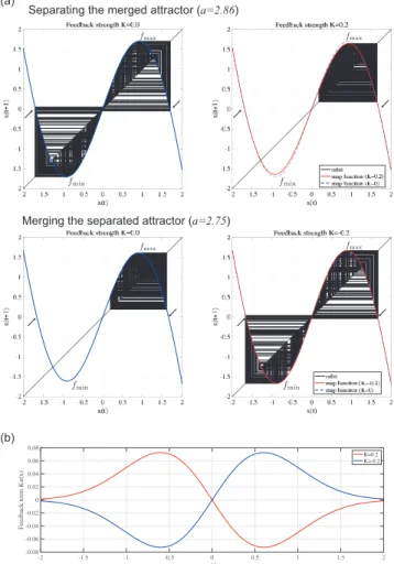
Fig. 1 Overview of the “reduced region of orbit” (RRO) feedback control method for discrete chaotic systems. (a) Effect of separating the merged attractor (upper) and that for merging the separated attractor (lower). Here fmax,minindicate the local maximum and minimum of map functions of F(x(t))+K u(x(t)). Arrows indicate the attractor merging points, i.e., F(fmax,min)+K u(fmax,min). (b) The feedback termK u(x)inK=0.2,−0.2 cases. (b=10, σ=0.6).
F(x)+Ku(x), if fmax,min reaches the regions ofxsatisfy- ing F(x)+Ku(x)−xd < 0 in the region for x > 0 and F(x)+Ku(x)−xd >0 in the region forx<0, respectively, the attractor merges.
We demonstrate the effect of the RRO feedback method in Fig. 1. In the left parts of Fig. 1(a), the map functions of F(x) and their orbits are represented corresponding to the cases without feedback signal (K = 0) for merged at- tractor (a = 2.86) and separated attractor (a = 2.75). In the merged attractor condition (a = 2.86), application of positive feedback strength (K=0.2) (see Fig. 1(b)) induces separation of the attractor into negative and positive regions, depending on the initial values of x(t), because decreasing
|fmax,min|leads to violation of the attractor merging condition F(fmax)+Ku(fmax)−xd <0,F(fmin)+Ku(fmin)−xd >0.
This separating effect was explored in our previous stud- ies [38], [43], [44]. Furthermore, in this study, we deal with the negative RRO feedback strength in addition to the positive RRO feedback strength. Under the condi-
tion for separated attractor (a = 2.75) (see lower part of Fig. 1(a)), application of negative RRO feedback strength (K =−0.2) leads to attractor merging and CCI by satisfying the attractor merging conditionF(fmax)+Ku(fmax)−xd <
0,F(fmin)+Ku(fmin)−xd >0 due to increasing|fmax,min|. 2.2 Chua’s Circuit Model with RRO Feedback Signals In this section, we expand the RRO feedback method to con- tinuous chaotic systems. Chua’s circuit is a chaotic system with a double-scroll attractor[47]described by the differen- tial equations
˙
x=α(y−x)−αf(x), (4)
y˙ =x−y+z, (5)
˙
z=−β y−γz. (6)
Here, the function f determines the non-linear characteris- tics of Chua’s diode as
f(x)=m1x+1
2(m0−m1)(|x+1| − |x−1|). (7) In this system, when the parameters are set to (β = 12.0732, γ = 0.0052,m0 = −0.1768,m1 = −1.1468), the chaotic attractor exhibits CCI between two separated regions [48]. The present study adopts this parameter set.
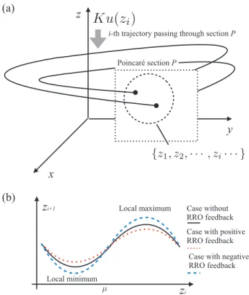
Figure 2(a) outlines our proposed RRO feedback con- trol method, as applied to continuous chaotic systems. The Poincaré return map of zi, which is the values of zwithin the Poincaré sectionP, is exhibited as follows:
zi+1 =FK(zi). (8)
The RRO feedback signal for theith (i=1,2,· · ·) trajectory crossing Poincaré sectionP is determined by the function u(zi) with a strength K (see Fig. 2(b)). In Refs.[38],[43]
and Sect. 2.1, we demonstrated that the merged attractor dis- playing CCI has a cubic-map structure and that reduction of the absolute values of the local maximum and minimum of map function results in the separation of the merged attractor (increase of these absolute values leads to the merging the separated attractor). In the present study, we therefore de- veloped the RRO feedback functionuto adjust the absolute values of the local maximum and minimum of the Poincaré return map functionFK(zi). Specifically, the RRO feedback signalKuwas added to Eq. (6), yielding
˙
z=−β y−γz+Ku(zi). (9) where, zi denotes the ith value of z when crossing the Poincaré section P = {(x, y,z)|x = 0, y < 0} [20]. This RRO feedback signalKu(zi) becomes constant during one cycle from Poincaré section to Poincaré section. We as- sumed that these signals are biased to the dynamics of zi corresponding to the direction of the sign of Ku(zi), i.e., positive (Ku(zi) >0) and negative (Ku(zi) <0) values of the RRO feedback signal induce an increase and decrease in the value ofzi+1, respectively. In this study, as well as
Fig. 2 Overview of the “reduced region of orbit” (RRO) feedback control method for continuous chaotic systems. (a) Orbit of a chaotic system and the RRO feedback signal. (b) Poincaré return map functionFK(zi)on Poincaré sectionP.
Fig. 3 Profile of RRO feedback signals given by Eq. (10) ((µ, σ) = (−3.7,0.3)).
for the RRO feedback functions used in our previous work [38],[43], the Gaussian RRO feedback functionu is given by
u(X)=−(X−µ) 1
√2πσexp(−(X−µ)2
2σ2 ), (10)
whereµis set to a division for attractor ofzi. In this study, we set(µ, σ) =(−3.7,0.3)(see the profile of functionuin Fig. 3).
To evaluate the synchronization with an input signal, the sinusoidal signalS(t)is applied to ˙zas follows:
˙
z=−β y−γz+Ku(zi)+S(t). (11) Here,S(t)representsAssin(2πfst).
2.3 Evaluation Methods
According to the attractor merging condition for the discrete cubic map described in Sect. 2.1 and in Refs.[38],[43], to evaluate the effect of RRO feedback signals, we use the condition for attractor merging:
FK(fmax)−µ <0, (12)
FK(fmin)−µ >0. (13)
Here fmax,minindicate the local maximum and minimum of FK(zi), respectively. Otherwise, the condition corresponds to the attractor separating.
Under the condition of attractor merging, the orbit of zihops betweenzi ≤ µandzi > µregions, which is called CCI of zi. To evaluate the synchronization of CCI of zi with a weak input sinusoidal signal, we use the strength of distribution for the interval term of CCI around the period ofTs =1/fs[49]:
P1=Z 1.25Ts 0.75Ts
P(Tcci)dTcci. (14) Here, P(Tcci) exhibits the probability distribution for the interval term of CCI ofzi, i.e.,Tcci=tk+1−tk(k=1,2,· · ·) (tkis time at which the CCI arises).
3. Results
3.1 Chua’s Circuit without RRO Feedback Signal
Figure 4 shows a bifurcation diagram ofzi as a function of the internal system parameter α, in the absence of a RRO feedback signal (K =0). Asαincreases through a period- doubling bifurcation, the chaotic state appears when α &
8.42. When 8.42 . α . 8.48, zi is confined within the range−4.5 .zi .−3.7 or−3.7.zi .−2.5, depending on the initial condition. However, whenα&8.48,zi oscillates between these regimes, thus demonstrating CCI.
3.2 Chua’s Circuit with a RRO Feedback Signal
For a fixed value of the internal system parameterα=8.52, the system state exhibits CCI when there is no RRO feedback (K =0). Then, the RRO feedback signalKu(zi)is applied.
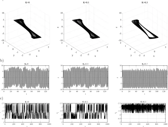
Figure 5 shows a bifurcation diagram of zi, plotted as a function of the RRO feedback strengthK. Typical examples of time-series of (x, y,z), z(t), and zi in K = 0,0.1,0.3 are represented in Fig. 6. For 0 . K . 0.21, zi exhibits CCI in the ranges −4.5 . zi . −3.7 and −3.7 . zi .
−2.5 (see the representative example for zi in the left and middle parts of Fig. 6(c)). However, asK increases beyond
≈0.21,zibecomes constrained within−4.5.zi .−3.7 or
−3.7 . zi .−2.5, depending on the initial values (see the representative example ofziin the right part of Fig. 6(c)).
Next, the negative RRO feedback signal is applied to
Fig. 4 System behavior of Chua’s circuit without a RRO feedback signal.
Bifurcation diagram of zi, plotted as a function of the internal system parameterα. Two kinds ofzi time series are plotted, corresponding to different initial values: (x(0), y(0),z(0)) = (−6.0489,0.0839,8.7739) (plotted with black points) and(6.0489,−0.0839,−8.7739)(plotted with red points). With increasingα, the separated attractor is merged. (β= 12.0732, γ=0.0052,m0=−0.1768,m1=−1.1468,K=0).
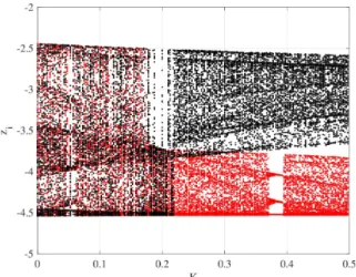
Fig. 5 System behavior of Chua’s circuit with an applied RRO feedback signal. Bifurcation diagram ofzi, plotted as a function of the RRO feedback strength K. Two kinds of zi time series are plotted, corresponding to different initial values: (x(0), y(0),z(0)) = (−6.0489,0.0839,8.7739) (plotted with black points) and(6.0489,−0.0839,−8.7739)(plotted with red points). With increasing strength of the positive feedback signal, the merged attractor is separated. (α=8.52, β=12.0732, γ=0.0052,m0=
−0.1768,m1=−1.1468).
Chua’s circuit under the condition that the attractor is sep- arating when there is no RRO feedback (K = 0) corre- sponding to α = 8.46. Figure 7 shows a bifurcation di- agram of zi, plotted as a function of the RRO feedback strength K. Typical examples of time-series of (x, y,z), z(t), andzi inK = 0,−0.1,−0.2 are represented in Fig. 8.
For −1.3 . K ≤ 0, zi is constrained in−4.5 . zi .−3.7 or −3.7 . zi . −2.5 (see the representative example for zi in the left and middle parts of Fig. 8(c)). However, as K decreases to less than≈ −1.3, zi exhibits CCI between
−4.5. zi .−3.7 and−3.7. zi .−2.5 (see the represen-
Fig. 6 Typical time-series of system behavior of Chua’s circuit with an applied positive RRO feedback signal (corresponding to Fig. 5). (α=8.52, β=12.0732, γ=0.0052,m0=−0.1768,m1=−1.1468).
Fig. 7 System behavior of Chua’s circuit with an applied negative RRO feedback signal. Bifurcation diagram ofzi, plotted as a function of the RRO feedback strengthK. Two kinds ofzitime series are plotted, corresponding to different initial values:(x(0), y(0),z(0))=(−6.0489,0.0839,8.7739) (plotted with black points) and(6.0489,−0.0839,−8.7739)(plotted with red points). With increasing absolute value of strength of the negative feed- back signal, the separated attractor is merged. (α=8.46, β=12.0732, γ= 0.0052,m0=−0.1768,m1=−1.1468).
tative example ofziin the right part of Fig. 8(c)).
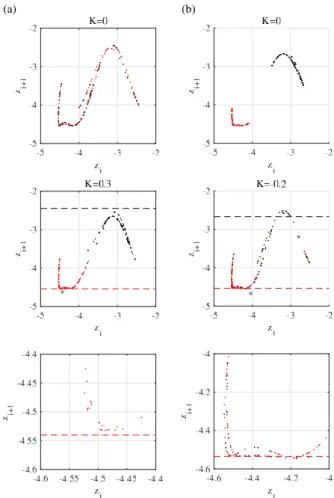
Figure 9(a) shows the return maps ofzi on a Poincaré section in the cases corresponding to K = 0,0.3 in Fig. 6.
The cubic-map structure for the map functionFK(zi)in the case without an applied RRO feedback signal is confirmed.
On the other hand, in the presence of a RRO feedback signal, the absolute values of the local maximum of the map func- tion FK(zi) are reduced, and the separation of the merged attractor is also confirmed. This effect of the RRO feed- back signal is consistent with our previous findings for a discrete cubic map[38],[43]. Here, the change to the value of the local minimum of the map function is less in com- parison with the change of the local maximum of the map function FK(zi). Moreover, this effect is evaluated by the attractor merging conditions for Eqs. (12) and (13). Ac- cording to the evaluation of the condition based on fmax (Eq. (12)), FK(fmax)−µ ≈ −2.8 < 0 (attractor merging) and FK(fmax)−µ ≈ 0.22 > 0 (attractor separating) are satisfied in the K = 0,0.3 cases, respectively. By con- trast, according to the evaluation of the condition based on fmin (Eq. (13)), in K = 0.3 corresponding to the attrac- tor separating, the attractor separating condition is satisfied (FK(fmin)−µ≈ −0.47<0), although whenK =0, corre-
Fig. 8 Typical time-series of system behavior of Chua’s circuit with an applied negative RRO feedback signal (corresponding to Fig. 7). (α=8.46, β=12.0732, γ=0.0052,m0=−0.1768,m1=−1.1468).
sponding to attractor merging, the attractor merging condi- tion is not satisfied (FK(fmin)−µ≈ −0.72<0). This might be attributed to the fact that the slope ofFK(zi)at around fmin(zi ≈ −4.5) is too steep to estimate the map function precisely (see the middle part in Fig. 9(a)).
In Fig. 9(b), the map functionFK(zi)corresponding to K =0,−0.2 cases in Fig. 8 are represented. In the case with- out an applied RRO feedback signal (K =0), the attractor is divided into−4.5 . zi . −4 and −3.5 . zi . −2.5.
While applying a negative RRO feedback signal (K=−0.2), the absolute values of the local maximum of the map func- tionFK(zi)are increased, and then the attractor is merged.
Here, as well as the positive feedback case in Fig. 9(a), the changing values of the local minimum of the map function are smaller in comparison with the ones for the local max- imum of the map functionFK(zi). Moreover, according to the evaluation of the condition based on fmax (Eq. (12)), FK(fmax) − µ ≈ 0.21 > 0 (attractor separating) and FK(fmax)−µ≈ −0.09<0 (attractor merging) are satisfied in theK =0,−0.2 cases, respectively. By contrast, according to the evaluation of the condition based on fmin(Eq. (13)), whenK =0, corresponding to the attractor separating, the attractor separating condition forFK(fmin)−µ≈ −0.67<0 is satisfied, although whenK =−0.2, corresponding to the
attractor merging, the attractor merging condition is not sat- isfied (FK(fmin)−µ≈ −0.60< 0). This might be for the same reason as in the positive feedback case, whereby the slope of FK(zi)at around fmin(zi ≈ −4.5) is too steep to estimate the map function precisely (see the middle part of Fig. 9(b)).
3.3 Inducing Chaotic Resonance with a RRO Feedback Signal
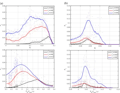
The signal response against a weak sinusoidal signal (S(t)= Assin(2πfst),As = 10−3) is evaluated. The upper parts of Fig. 10 show the strength of distribution for the interval term of CCI: P1 as a function of the feedback strength K in the cases of positive RRO feedback strength (α =8.52) and negative RRO feedback strength (α=8.46). The lower parts of Fig. 10 show scatter plots of P1 andFK(fmax)−µ given by Eq. (12) under the condition without a sinusoidal signal. Here, the attractor merging condition based on fmax is used, rather than the condition based on fminaccording to the results in Sect. 3.2. In both cases, the tendency of the unimodal maximum peak of P1 is confirmed at around the feedback strengthKfor the appearance of the attractor merg- ing (FK(fmax)−µ≈0). Moreover, the peak values depend
Fig. 9 Return map ofzi on a Poincaré section, in the absence of RRO feedback signal (upper graph) and presence of RRO feedback signal (middle graph). The lower graph is magnified at around∗in the middle graph. The red and black points correspond to the initial conditions(x(0), y(0),z(0))= (−6.0489,0.0839,8.7739)and(6.0489,−0.0839,−8.7739), respectively.
The black and red dashed lines in the lower part indicate the local max- imum and minimum values of the map functionFK(zi), respectively, in the case without feedback (K =0). (β = 12.0732, γ =0.0052,m0 =
−0.1768,m1=−1.1468,α=8.52 ((a)),α=8.46 ((b))).
on the input signal frequency fs. From these results, it can be interpreted that the RRO feedback signal induces an ap- propriate chaotic state around attractor-merging bifurcation for the chaotic resonance.
4. Discussion and Conclusion
In this study, we extended the RRO feedback method, which was developed for controlling attractor-merging bifurcation in discrete chaotic systems, to continuous chaotic systems by focusing on the map function on the Poincaré section. We applied the extended RRO feedback method to Chua’s cir- cuit as a continuous chaotic system with CCI. Moreover, we evaluated the signal response against a weak sinusoidal sig- nal under the RRO feedback signals. The results confirmed that a merged attractor and a separated attractor can be sepa- rated and merged, respectively, by the RRO feedback signal with sufficiently strong strength. In both cases, the ability of signal response is maximized at around the strength of the
RRO feedback signal for attractor merging bifurcation, i.e., the chaotic resonance can be induced by the RRO feedback signals.
The mechanism of the RRO feedback method that merges and separates the attractor must be considered. With regard to the separating effect, Refs.[38],[43]show that, in discrete chaotic systems, the merged attractor in the presence of CCI exhibits a cubic-map structure, and the reduction of the absolute values of the local maximum and minimum of the map function by the RRO feedback signal has the effect of separating the merged attractor. Moreover, in Sect. 2.1, we showed that the RRO feedback signal with negative feed- back strength exhibits the effect of merging the separated attractor due to increasing the absolute values of the local maximum and minimum of map function. For developing the RRO feedback method for Chua’s circuit, the local maxi- mum and minimum of the functionuare set to approximately equate the local minimum and maximum of the map function of FK(zi), respectively, as well as those of discrete chaotic systems [38],[43]. In addition, the RRO feedback signal is set to a constant value Ku(zi)defined by Eq. (9), during one cycle from Poincaré section to Poincaré section. We assumed that these signals are biased to the dynamics ofzi corresponding to the direction of sign ofKu(zi), i.e., posi- tive (Ku(zi) >0)/negative (Ku(zi) <0) values of the RRO feedback signal induce increase/decrease in the value ofzi+1, respectively. Owing to this effect, the absolute values of the local maximum/minimum of the map function are reduced and increased for the positive (K > 0 case) and negative (K <0 case) RRO feedback signals, respectively. This leads to the respective effects for separating and merging attractor.
Next, with regard to the signal response against a weak sinusoidal signal, the proposed RRO feedback sig- nals for Chua’s circuit can induce the unimodal maxi- mum peak of signal response with the dependency on in- put frequency around the attractor-merging bifurcation (see Fig. 10). The reason for enhancing the signal response of CCI at the attractor-merging bifurcation is considered. Near the attractor-merging bifurcation point, CCI seldom occurs in the condition without an input signal. However, with an input signal, the influence of the input signal leads the attractor to switch according to the period of the input sig- nal. Consequently, this effect enhances the signal response.
It is known that, in discrete and continuous chaotic sys- tems with CCI, the signal response in chaotic resonance is also maximized at around the attractor-merging bifurcation, and its response exhibits dependency on the input frequency [19]. We previously reported that these characteristics are maintained under RRO feedback signals in discrete chaotic systems [38],[44], [45]. Therefore, the characteristics of chaotic resonance observed in this study are congruent with the previous findings of[19],[38],[44],[45].
We now turn to a discussion of the limitations and fu- ture scope of this study. By expanding RRO feedback signals to Chua’s circuit, the system-specific assumption is not con- sidered. Therefore, it is assumed that the RRO feedback signals can be widely adopted for other continuous systems
Fig. 10 Strength of distribution for interval term of chaos–chaos intermittency (CCI):P1as a function of feedback strengthK(upper). Scatter plots ofP1given by the upper part andFK(fmax)−µunder the condition without a sinusoidal signal (given by Eq. (12)) (lower). (a) Positive feedback strength case (α=8.52). (b) Negative feedback strength case (α=8.46). In both feedback cases, the value ofP1exhibits an unimodal maximum peak at around the attractor merging point. (β=12.0732, γ= 0.0052,m0=−0.1768,m1=−1.1468,As=10−3).
with attractor-merging bifurcation where chaotic resonance have been observed, such as the Lorenz system and the duff- ing oscillator[9],[19],[23], for inducing chaotic resonance.
This must be verified in a future study. As a limitation of the proposed RRO feedback method, when controlling the local minimum of the map function ofzi in Chua’s circuit, the change in the value of the RRO feedback signal is less in comparison with that for the local maximum (see Fig. 9).
This might be attributed to the fact that the return map ofzi is not a complete odd function, while the RRO feedback sig- nal is applied based on the assumption of complete function.
Furthermore, we did not succeed at estimating the attractor merging condition based on fminbecause of the steep slope of the map function. To address these problems, we must develop RRO feedback signals that accurately correspond to the return map on the Poincaré section, and a highly accurate estimation method is needed for the map function. More- over, to adopt the RRO feedback method to chaotic systems with more complex structure of attractor, one might consider the setting for several Poincaré sections and a RRO feedback signal based on the map function estimated using these sec- tions. In addition, application of the RRO feedback method to continuous neural systems should be investigated in future studies.
In conclusion, this study is the first to report the ap- plication of RRO feedback to a continuous chaotic system.
The findings will open fresh avenues for expanding device development, which to date has been limited to stochastic resonance, to chaotic resonance.
Acknowledgments
This work was supported by the JSPS KAKENHI for Early- Career Scientists Grant Number 18K18124 (SN) and the Grant-in-Aid for Scientific Research (C) Grant Number 18K11450 (TY).
References
[1] Q. Wang, Z. Duan, M. Perc, and G. Chen, “Synchronization tran- sitions on small-world neuronal networks: Effects of information transmission delay and rewiring probability,” EPL (Europhysics Let- ters), vol.83, no.5, p.50008, 2008.
[2] Q. Wang, M. Perc, Z. Duan, and G. Chen, “Synchronization tran- sitions on scale-free neuronal networks due to finite information transmission delays,” Phys. Rev. E, vol.80, no.2, p.026206, 2009.
[3] Q. Wang, G. Chen, and M. Perc, “Synchronous bursts on scale-free neuronal networks with attractive and repulsive coupling,” PLoS ONE, vol.6, no.1, p.e15851, 2011.
[4] S. Majhi, M. Perc, and D. Ghosh, “Chimera states in uncoupled neurons induced by a multilayer structure,” Sci. Rep., vol.6, 2016.
[5] J. Hizanidis, N.E. Kouvaris, Z.L. Gorka, A. Díaz-Guilera, and C.G.
Antonopoulos, “Chimera-like states in modular neural networks,”
Sci. Rep., vol.6, p.19845, 2016.
[6] B.K. Bera, D. Ghosh, and T. Banerjee, “Imperfect traveling chimera states induced by local synaptic gradient coupling,” Phys. Rev. E, vol.94, no.1, p.012215, 2016.
[7] A. Pikovsky, M. Rosenblum, and J. Kurths, Synchronization: A Uni- versal Concept in Nonlinear Sciences, Cambridge University Press, 2003.
[8] V.S. Anishchenko, V. Astakhov, A. Neiman, T. Vadivasova, and L. Schimansky-Geier, Nonlinear Dynamics of Chaotic and Stochastic
Systems: Tutorial and Modern Developments, Springer Science &
Business Media, 2007.
[9] S. Rajasekar and M.A. Sanjuan, Nonlinear Resonances, Springer, 2016.
[10] R. Benzi, A. Sutera, and A. Vulpiani, “The mechanism of stochastic resonance,” J. Phys. A: Math. Gen., vol.14, no.11, pp.L453–L457, 1981.
[11] G.P. Harmer, B.R. Davis, and D. Abbott, “A review of stochastic resonance: Circuits and measurement,” IEEE Trans. Instrum. Meas., vol.51, no.2, pp.299–309, 2002.
[12] F. Moss and K. Wiesenfeld, “The benefits of background noise,” Sci.
Am., vol.273, no.2, pp.66–69, 1995.
[13] P. Hänggi, “Stochastic resonance in biology how noise can enhance detection of weak signals and help improve biological information processing,” ChemPhysChem, vol.3, no.3, pp.285–290, 2002.
[14] T. Mori and S. Kai, “Noise-induced entrainment and stochastic resonance in human brain waves,” Phys. Rev. Lett., vol.88, no.21, p.218101, 2002.
[15] M.D. McDonnell and L.M. Ward, “The benefits of noise in neu- ral systems: bridging theory and experiment,” Nat. Rev. Neurosci., vol.12, no.7, pp.415–426, 2011.
[16] S. Nobukawa and H. Nishimura, “Enhancement of spike-timing- dependent plasticity in spiking neural systems with noise,” Int. J.
Neural Syst., vol.26, no.5, p.1550040, 2016.
[17] S. Nobukawa, R. Hashimoto, H. Nishimura, T. Yamanishi, and M. Chiba, “Noise-induced phenomena in the Kaldor business cy- cle model,” Trans. ISCIE, vol.30, no.12, pp.459–466, 2017.
[18] H. Nishimura, N. Katada, and K. Aihara, “Coherent response in a chaotic neural network,” Neural Process. Lett., vol.12, no.1, pp.49–
58, 2000.
[19] V.S. Anishchenko, V. Astakhov, A. Neiman, T. Vadivasova, and L. Schimansky-Geier, Nonlinear Dynamics of Chaotic and Stochastic Systems: Tutorial and Modern Developments, Springer Science &
Business Media, 2007.
[20] Q. Li, H. Zeng, and X.S. Yang, “On hidden twin attractors and bifurcation in the Chua’s circuit,” Nonlinear Dynam., vol.77, no.1-2, pp.255–266, 2014.
[21] S. Nobukawa, H. Nishimura, and T. Yamanishi, “Evaluation of chaotic resonance by Lyapunov exponent in attractor-merging type systems,” International Conference on Neural Information Process- ing, pp.430–437, Springer, 2016.
[22] G.L. Baker, G.L. Baker, and J.P. Gollub, Chaotic Dynamics: An Introduction, Cambridge University Press, 1996.
[23] I. Kovacic and M.J. Brennan, The Duffing Equation: Nonlinear Os- cillators and Their Behaviour, John Wiley & Sons, 2011.
[24] S.H. Strogatz, Nonlinear Dynamics and Chaos: With Applications to Physics, Biology, Chemistry, and Engineering, CRC Press, 2018.
[25] N. Schweighofer, K. Doya, H. Fukai, J.V. Chiron, T. Furukawa, and M. Kawato, “Chaos may enhance information transmission in the inferior olive,” Proc. National Academy of Sciences of the United States of America, vol.101, no.13, pp.4655–4660, 2004.
[26] I.T. Tokuda, C.E. Han, K. Aihara, M. Kawato, and N. Schweighofer,
“The role of chaotic resonance in cerebellar learning,” Neural Net- works, vol.23, no.7, pp.836–842, 2010.
[27] S. Nobukawa and H. Nishimura, “Signal response in Velarde- Llinás model of inferior olive neuron,” IEICE Trans. Fundamentals (Japanese Edition), vol.J96-A, no.1, pp.1–11, Jan. 2013.
[28] S. Nobukawa, H. Nishimura, T. Yamanishi, and J.Q. Liu, “Analysis of chaotic resonance in Izhikevich neuron model,” PloS ONE, vol.10, no.9, p.e0138919, 2015.
[29] S. Nobukawa and H. Nishimura, “Chaotic resonance in coupled in- ferior olive neurons with the Llinás approach neuron model,” Neural Comput., vol.28, no.11, pp.2505–2532, Nov. 2016.
[30] S. Nobukawa, H. Nishimura, and T. Yamanishi, “Chaotic resonance in typical routes to chaos in the Izhikevich neuron model,” Sci. Rep., vol.7, p.1331, 2017.
[31] Y. Kurita, M. Shinohara, and J. Ueda, “Wearable sensorimotor en-
hancer for fingertip based on stochastic resonance effect,” IEEE Trans. Human-Mach. Syst., vol.43, no.3, pp.333–337, 2013.
[32] L.R. Enders, P. Hur, M.J. Johnson, and N.J. Seo, “Remote vibrotactile noise improves light touch sensation in stroke survivors’ fingertips via stochastic resonance,” J. NeuroEngineering and Rehabilitation, vol.10, no.1, p.105, 2013.
[33] N.J. Seo, M.L. Kosmopoulos, L.R. Enders, and P. Hur, “Effect of remote sensory noise on hand function post stroke,” Front. Hum.
Neurosci., vol.8, p.934, 2014.
[34] Y. Kurita, Y. Sueda, T. Ishikawa, M. Hattori, H. Sawada, H. Egi, H. Ohdan, J. Ueda, and T. Tsuji, “Surgical grasping forceps with enhanced sensorimotor capability via the stochastic resonance ef- fect,” IEEE/ASME Trans. Mechatronics, vol.21, no.6, pp.2624–
2634, 2016.
[35] Y. Tadokoro, H. Tanaka, Y. Nakashima, T. Yamazato, and S. Arai,
“Enhancing a BPSK receiver by employing a practical parallel net- work with stochastic resonance,” Nonlinear Theory and Its Applica- tions, IEICE, vol.10, no.1, pp.106–114, 2019.
[36] O. Van der Groen, M.F. Tang, N. Wenderoth, and J.B. Mattingley,
“Stochastic resonance enhances the rate of evidence accumulation during combined brain stimulation and perceptual decision-making,”
PLoS Comput. Biol., vol.14, no.7, p.e1006301, 2018.
[37] S. Nobukawa, H. Nishimura, and N. Katada, “Chaotic resonance by chaotic attractors merging in discrete cubic map and chaotic neural network,” IEICE Trans. Fundamentals (Japanese Edition), vol.J95-A, no.4, pp.357–366, April 2012.
[38] S. Nobukawa, H. Nishimura, T. Yamanishi, and H. Doho, “Control- ling chaotic resonance in systems with chaos-chaos intermittency using external feedback,” IEICE Trans. Fundamentals, vol.E101-A, no.11, pp.1900–1906, Nov. 2018.
[39] E. Ott, C. Grebogi, and J.A. Yorke, “Controlling chaos,” Phys. Rev.
Lett., vol.64, no.11, pp.1196–1199, 1990.
[40] K. Pyragas, “Continuous control of chaos by self-controlling feed- back,” Phys. Lett. A, vol.170, no.6, pp.421–428, 1992.
[41] H. Nakajima, “On analytical properties of delayed feedback control of chaos,” Phys. Lett. A, vol.232, no.3-4, pp.207–210, 1997.
[42] W. Jiang, Q. Guo-Dong, and D. Bin, “H∞variable universe adaptive fuzzy control for chaotic system,” Chaos, Solitons & Fractals, vol.24, no.4, pp.1075–1086, 2005.
[43] S. Nobukawa, H. Nishimura, T. Yamanishi, and H. Doho, “In- duced synchronization of chaos-chaos intermittency maintaining asynchronous state of chaotic orbits by external feedback signals,”
IEICE Trans. Fundamentals, vol.E102-A, no.3, pp.524–531, March 2019.
[44] S. Nobukawa and N. Shibata, “Controlling chaotic resonance using external feedback signals in neural systems,” Sci. Rep., vol.9, no.1, p.4990, 2019.
[45] S. Nobukawa, N. Shibata, H. Nishimura, H. Doho, N. Wagatsuma, and T. Yamanishi, “Resonance phenomena controlled by external feedback signals and additive noise in neural systems,” Sci. Rep., vol.9, p.12630, 2019.
[46] S. Nobukawa, N. Shibata, A. Miyazaki, H. Nishimura, T. Yamanishi, and H. Doho, “Chaos-chaos intermittency controlled by external feedback signals in Chua’s circuit,” Proc. SICE Annual Conference 2019, FrC03.3, 2019.
[47] L.O. Chua, Introduction to Nonlinear Network Theory, McGraw- Hill, 1969.
[48] G. Leonov, N. Kuznetsov, and V. Vagaitsev, “Localization of hidden Chua’s attractors,” Phys. Lett. A, vol.375, no.23, pp.2230–2233, 2011.
[49] S. Sinha and B.K. Chakrabarti, “Deterministic stochastic resonance in a piecewise linear chaotic map,” Phys. Rev. E, vol.58, no.6, pp.8009–8012, 1998.
Sou Nobukawa graduated from the De- partment of Physics and Earth Sciences of the University of Ryukyus in 2006, completed the doctoral program at the University of Hyogo and received a Ph.D. degree in 2013. He is an Asso- ciate Professor in the Department of Computer Science, Chiba Institute of Technology. His research interests include chaos/bifurcation and neural networks. He is a member of IEEE, INNS, IEICE, IPSJ, SICE, ISCIE, and others, and was awarded the SICE Encouragment Prize in 2016, as well as the Young Researcher Award by the IEEE Computational In- telligence Society Japan Chapter in 2019 and Best Paper Award of The 29th Symposium on Fuzzy, Artificial Intelligence, Neural Networks and Computational Intelligence in 2019.
Hirotaka Doho graduated from the Faculty of School of Education, Hiroshima University, in 1985, completed the Master’s program at Hyogo University of Education, receiving a Master’s degree in 2000. He is a Professor in the Faculty of Education, Kochi University. His research interests include nonlinear dynamics of neural networks.
Natsusaku Shibata graduated from the Department of Computer Science, Chiba Insti- tute of Technology, in 2019 and is a Master’s student at this institute. He is a member of IEICE and ISCIE. His research interests include chaos/bifurcation in neural networks.
Haruhiko Nishimura graduated from the Department of Physics, Shizuoka University, in 1980, completed the doctoral program at Kobe University, and received a Ph.D. degree in 1985.
He is currently a Professor in the Graduate School of Applied Informatics, University of Hyogo. His research interests include intelli- gent systems science based on several architec- tures, such as neural networks and complex sys- tems. He is also presently engaged in research on biomedical, healthcare, and high confidence sciences. He is a member of the IEEE, IEICE, IPSJ, ISCIE, JNNS, and others, and was awarded the ISCIE paper prize in 2001 and the JSKE paper prize in 2010.
Teruya Yamanishi received a Master’s de- gree in science education from Kobe University in 1991, and a Ph.D. degree in physics from Kobe University in 1994. He is a Professor at Fukui University of Technology, where he works on mathematical information science for the brain and develops optimization tools for the behavior of autonomous robots.