PAPER Special Section on Circuits and Systems
An Architecture for Real-Time Retinex-Based Image Enhancement and Haze Removal and Its FPGA Implementation
Dabwitso KASAUKA†, Kenta SUGIYAMA†,Nonmembers, Hiroshi TSUTSUI†a),Senior Member, Hiroyuki OKUHATA††,Member,andYoshikazu MIYANAGA†,Fellow
SUMMARY In recent years, much research interest has developed in image enhancement and haze removal techniques. With increasing demand for real time enhancement and haze removal, the need for efficient architec- ture incorporating both haze removal and enhancement is necessary. In this paper, we propose an architecture supporting both real-time Retinex-based image enhancement and haze removal, using a single module. Efficiently leveraging the similarity between Retinex-based image enhancement and haze removal algorithms, we have successfully proposed an architecture supporting both using a single module. The implementation results reveal that just 1% logic circuits overhead is required to support Retinex-based image enhancement in single mode and haze removal based on Retinex model. This reduction in computation complexity by using a single mod- ule reduces the processing and memory implications especially in mobile consumer electronics, as opposed to implementing them individually us- ing different modules. Furthermore, we utilize image enhancement for transmission map estimation instead of soft matting, thereby avoiding fur- ther computation complexity which would affect our goal of realizing high frame-rate real time processing. Our FPGA implementation, operating at an optimum frequency of 125 MHz with 5.67 M total block memory bit size, supports WUXGA (1,920×1,200) 60 fps as well as 1080p60 color input.
Our proposed design is competitive with existing state-of-the-art designs.
Our proposal is tailored to enhance consumer electronic such as on-board cameras, active surveillance intrusion detection systems, autonomous cars, mobile streaming systems and robotics with low processing and memory requirements.
key words: real time processing, FPGA, Retinex-based image enhance- ment, haze removal
1. Introduction
Digital image and video processing plays an essential role in modern day consumer electronics, with the increasing demand in digital media driven by current social trends.
With continued advancement in digital imaging applications, real-time image (video) enhancement and haze removal are among key research topics influencing consumer electronics.
Image enhancement schemes can be categorized into two groups; adaptive and non-adaptive schemes. Non- adaptive schemes compensate each pixel value uniformly based on given equations [1], while adaptive schemes re- fer surrounding pixels to reproduce a high quality image.
Retinex theory[2]–[7]is a well-known adaptive image en- Manuscript received August 31, 2018.
Manuscript revised January 10, 2019.
†The authors are with Graduate School of Information Sci- ence and Technology, Hokkaido University, Sapporo-shi, 060-0814 Japan.
††The author is with Soliton Systems K. K., Osaka-shi, 530-0017 Japan.
a) E-mail: [email protected] DOI: 10.1587/transfun.E102.A.775
hancement scheme, its variant which we shall consider in this paper. Haze removal methods can be categorized as;
single and multiple image schemes. Single-image schemes are more popular, requiring less overhead.
The quality of images and video taken from outdoor scenes is influenced by scattering of light which occurs be- fore reaching the camera sensor. The amount of scattering depends on the distance between the scene points and the sensor, making degradation spatial-variant[8]. In haze (fog) weather, an elevated presence of atmospheric particles such as water-droplets results in more scattering, resulting in low contrast and color fidelity images. Scattering is caused by two basic phenomena, which are attenuation and airlight.
According to[8],[9], haze removal depends upon the un- known depth information. This particularly makes haze re- moval a challenging task. Haze removal is highly desired in computer vision applications. It not only serves to sig- nificantly increase the visibility of the scene and correct the color shift, it can also benefit many vision algorithms and advanced image editing.
Both Retinex-based image enhancement and haze re- moval are computation costly. Considering real-time pro- cessing in applications such as monitoring systems, au- tonomous cars, and live streaming systems, there still re- mains much room for the development of efficient hardware implementation of image enhancement and haze removal.
Motivate by this, in this paper we propose an architecture supporting both real-time Retinex-based image enhancement and haze removal, at low memory and process overhead uti- lizing a single module.
Our proposed implementation and architecture, based on our previous work[10], efficiently supports both Retinex- based image enhancement and haze removal. Efficiently leveraging the similarity between Retinex-based image en- hancement and haze removal, and modifying the process, we present a novel architecture optimized for both processes at low overhead cost.
This paper is organized as follows. In Sect. 2 we high- light some related works. In Sect. 3, we briefly describe the Retinex-based image enhancement proposed in[10]. In Sect. 4, we discuss haze removal. In Sect. 5, we show the detail of the proposed approach and architecture. In Sect. 6, we present the implementation result. Finally in Sect. 7, we conclude this paper.
Copyright © 2019 The Institute of Electronics, Information and Communication Engineers
2. Related Work
Various researchers have proposed algorithms to address im- age enhancement and haze removal, commonly independent of each other. Considering Retinex based image enhance- ment, Shen and Hwang[11]presented a color image process- ing using a robust envelope to improve the visual appearance of an image. Guo et al.[12]introduced a visibility restoration method for a single image using Retinex algorithm on lumi- nance component, while Fattal[13]presented a novel trans- mission estimation method to increase scene visibility and recover haze-free image. Marsi and Giovanni[14]proposed and FPGA implementation for illuminance-reflectance video enhancement in a single module. In Shiau et al.[15], hard- ware implementation of haze removal is presented. They, [15], proposed an 11-stage pipelined hardware architecture.
However, these existing algorithms highlighted require high memory and computation, more so at higher resolutions.
Furthermore, most of these algorithms are optimized for ei- ther enhancement or haze removal only.
Furthermore, Ren, Wenqi, et al.[16]proposed a multi- scale convolutional neural network dehazing method. In this proposal, a holistic prediction of the transmission map using a dataset trained neural network is utilized. In this case train- ing is required in order to learn mapping, which is a complex task. In[17], an end-to-end image dehazing method called Densely Connected Pyramid Dehazing Network (DCPDN) is proposed. This jointly learns the transmission map, atmo- spheric light and dehazing all together by directly embedding the atmospheric scattering model into the network. By this, the method follows the physics-driven scattering model for dehazing. Dataset training is required in this implementation as is in[16].
Galdran, Adrian, et al.[18] presents a dual relation- ship between image dehazing and non-uniform illumination separation, applying Retinex operation on an inverted im- age followed by another image inversion in order to obtain a dehazed output. It is generally concluded that Retinex and dehazing can be connected by a simple linear relationship.
The outcome of this was to demonstrate the general usability of existing Retinex implementations for haze removal based on a simple linear relationship, not to provide output perfor- mance gain over existing approaches.
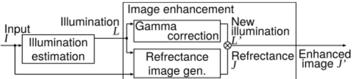
3. Retinex-Based Image Enhancement
The Retinex theory[19]deals with compensation for illumi- nation effects in images. This introduces the lightness and color perception of the human visual system, and is based on the property of the color constancy phenomenon, in that humans can recognize and match colors under a wide range of different illuminations. This theory decomposes an input imageI(x)into two different images, defined by
I(x)=L(x)J(x), (1)
where L(x) and J(x) is the illumination image and re-
Fig. 1 The flow of the Retinex image enhancement.
flectance image, respectively. The benefits of such decom- position include the possibility of removing illumination ef- fects, enhancing image edges, and correcting the colors in images by removing illumination induced color shifts[12].
Image enhancement can be achieved by extractingL(x) from I(x) in order to generate J(x), as an illumination- independent image. The logarithmic expression of the re- flectance imageJ(x)can be expressed by
J(x)= I(x) L(x),
j(x)=i(x)−l(x). (2)
wherei=logI,l=logL, andj =logJ. Figure 1 highlights the general flow chart of Retinex-based algorithms.
Several illumination models are proposed so far based on Retinex theory, such as Path-based[3], Center/Surround based[4]and Variational model[20], just to mention a few.
Path and center based models are easily implemented but require a large number of parameters. Hence, these were not considered in our FPGA realization as the require more memory and computation resources than proposed.
The variational model [20] (Kimmel’s variational model), assumes spatial smoothness of the illumination field.
In addition, knowledge of the limited dynamic range of the reflectance is used as a constraint in the recovery process. A modification of this variant was implemented in this paper, recognizing variational model as one of the most suitable models for practical applications in terms of computational cost and image quality, suitable for our real-time FPGA ar- chitecture[10].
The variational model algorithm is constructed to min- imize the following penalty function,
F[l]=Z
Ω
|∇l|2+α(i−l)2+β|∇(i−l)|2
dx, (3) whereαand βare weight parameters,iandl represent the logarithmic expression of input image I and illumination image L, respectively. Penalty terms, |∇l|2, (i −l)2, and
|∇(i−l)|2 represent spatial smoothness of the illumination image, closeness betweenlandi, and spatial smoothness of the reflectance imagej, respectively. The illumination image lwhich minimizes the penaltyF[l] is iteratively calculated using a projected normalized steepest descent algorithm.
Figure 1 illustrates the flow of the Retinex image en- hancement with illumination correction.
By utilizing such adaptive image enhancement meth- ods, halo artifacts are observed in the enhanced images.
These are caused because such methods utilize the constraint that the illumination image should be spatially smooth.
When the illumination is estimated in the regions around the edge with this constraint, these regions in reflectance image tend to be either over-enhanced or insufficiently enhanced.
Hence there are two types of halo artifacts; positive and neg- ative. In the variational model, positive halo artifacts are successfully suppressed using a constrainti ≤lin iterative calculation while leaving negative halo artifacts present[21].
Various halo effect suppression techniques have been inves- tigated in[11],[14], which however are computation costly.
In[21]we proposed a halo artifacts reduction method, with a small area overhead.
4. Haze Removal
The haze image model[13], [22]–[24], which consists of direct attenuation model and airlight model is generally ex- pressed by,
I(x)=J(x)T(x)+A(1−T(x)), (4) where I is the observed luminance representing the input haze image,Jis the scene radiance representing the restored haze-free image,T is the medium transmission describing the portion of the light that is not scattered and reaches the camera, andAis the global atmospheric light. The goal of haze removal is to recoverJfromIusing estimatedTandA by,
J(x)= I(x)−A
T(x) +A, (5)
In general,T and Aare estimated using dark channel prior[8]. The dark channel prior is a kind of statistics of the haze-free outdoor images. It is based on an observation that most local patches in the haze-free outdoor images contain some pixels which have very low intensities in at least one color channel. Hence the minimum intensity in such a patch should have a very low value. In[8], thedark channelof an arbitrary imageJis defined as
Jdark(x)= min
y∈Ω(x) min
c∈ {R,G,B}Jc(y)
!
, (6)
whereJcis the color channel ofJcomprising of RGB com- ponents, andΩ(x)depicts a local patch centered atx. The low intensity of the dark channels is due to shadows, colorful objects or surfaces and dark objects in images. According to the observation in[8], ifJis a haze-free outdoor image, the intensity ofJdarkis low and tends to be zero except for the sky region in an image. Due to additive airlight, a haze image is brighter than its haze-free version. Hence the dark channel of the haze image will have higher intensity in regions with denser haze. Therefore, the intensity of the dark channel is a rough approximation of the thickness of the haze.
In [8], the transmission T is determined using soft matting. However, this approach requires a high compu- tation cost. Motivated by this, some approaches use edge- preserving smoothing such as bilateral filters for estimating T with reasonable processing cost[25]. In our approach, we
use edge-preserving smoothing based on the cost minimiza- tion function in Eq. (3) and [26] to generate the transmis- sionT instead of soft matting. Hence, in a complimentary approach, we use Retinex-based image enhancement to sup- plement haze removal at a low overhead resource cost.
5. Proposed Architecture
The block diagram of our proposed FPGA architecture is shown in Fig. 2 and Fig. 5. The logic of this architecture is shown in Fig. 3. This architecture accommodates both Retinex-based enhancement and haze removal using a single module, with a low overhead resource cost as opposed to using separate modules.
This architecture consists of three parts (Figs. 2 and 3); (1) Gaussian pyramid generation part, (2) il- lumination/transmission estimation part, and (3) image enhancement/haze-removal part.
We utilize Gaussian pyramid downsampling in order to realize low block memory size hardware requirement. Con- sidering spatial smoothness characteristic of the illumination field, the effects of downsampling are tolerable.
Illumination and transmission estimation are performed on layers 5, 4, and 3 of Fig. 3, enabling accelerated itera- tions with low memory requirements. Figure 3 illustrates the scaling relationship between successive downsampled image layers, which are used as iterative inputs in the esti- mation stage. Therefore by downsampling, the size of the buffers required are significantly reduced since the size of layers 3, 4 and 5 are 1/64, 1/256 and 1/1024 of the reso- lution of the input image, respectively. The adaptation of Gaussian in our approach presents a computational efficient approximation, especially for FPGA. The original resolution is reconstructed using bi-linear interpolation, considering its low hardware cost. In order to combat blur effect inherent to interpolation, we implement the constrainti ≤ l. Figure 4 illustrates blur edge handling by this constraint. By applying this constraint to the interpolated image, the sharpness of edges is retained to a better degree, thereby countering loss of sharpness inherent to downsampling.
In Fig. 5, showing the illumination and transmission
Fig. 2 The block diagram of the proposed architecture[10].
Fig. 3 Layer hierarchy for illumination estimation.
Fig. 4 Edge preservation using constrainti≤l.
Fig. 5 Expanded view of Illumination and transmission estimation mod- ule.
estimation module of Fig. 2, we have the following:
GA(x, y)=∇l(k)j−1(x, y),
GB(x, y)=∇s(k)(x, y), µA=X
x
X
y
G(x, y)2, µB =−X
x
X
y
G(x, y)∇G(x, y), µNSD= µA
αµA+(1+β)µA, G(x, y)=−GA(x, y)+
α
l(kj−1)(x, y)−s(k)(x, y) +
β(GA(x, y)−GB(x, y)) (7)
where k is the layer number, j the iteration index is j = 1,2, ...,Tk andsrepresents decimated image. The illumina- tion/transmission estimation is given by,
l(k)j =max
l(k)j−1(x, y)−µNSDG(x, y),s(k)(x, y) (8) We utilized three 3×3 filters, each of them requiring 3 line buffers.
• 3 line buffers for calc GA (∇l): line width is 240,
• 3 line buffers for calc GB (∇s): line width is 240,
• 3 line buffers for calc G (∇G): line width is 240.
The components of our proposed architecture work in a pipeline manner. In this paper we do not utilize an external frame buffer to storing input frames temporally. To compen- sate for this, we leverage the close similarity characteristic of consecutive frames enabling estimation component reuse.
As shown in the Fig. 2, an input framet+2 is enhanced by using the illumination/ transmission estimated from a pre- ceding framet, without latency. If an external frame buffer which stores two successive input frames is used, each input frame can be enhanced with the corresponding estimated il- lumination with a latency of two frames delay. Hence, the advantage of our approach, further aided by our implementa- tion of Gaussian pyramid downsampling, is that no latency in frame processing is introduced, making real-time processing
more feasible.
In the Gaussian pyramid generation part, an RGB image is converted to HSV colorspace. The V component given by Eq. (9) is used as the initial estimation of the illumination image,L.
IV(x)= max
c∈ {R,G,B}Ic, (9)
Illumination component is estimated iteratively based on Eq. (3), by using Eq. (9) as an initial estimate argument.
Considering Eq. (6), calculation of the dark channel involves minimization over each pixel, over a local patch with trans- missionT(x) estimated using Eq. (3), in conjunction with our previously proposed minimization technique in[26].
From the definitions of Eqs. (3) and (4), we observe the following useful relationships between image enhancement and haze removal, which aid in the FPGA realization at a low overhead resource cost.
i = log(I), I: input
l = log(L), L: illumination/transmission j = log(J), J: reflectance/haze-free image where, in the case of image enhancement,
j(x) =i(x)−l(x)
J(x) =exp(−l(x))I(x), (10)
and, for haze removal, J(x) = I(x)−A
T(x) +A,
J(x) =exp(−t(x)) (I(x)−A)+A, (11) We formulate a generalized equation from Eq. (11) by replac- ingt(x)withl(x)based on our use of image enhancement for transmission estimation, yielding
J(x)=exp(−l(x)) (I(x)−A)+A, (12) Here, it should be noted that Eq. (10) is a special case of Eq. (12), where A=0. Furthermore, Eqs. (10) and (12) are efficiently suitable expression for our FPGA implementation, as we do not need to perform calculations in logarithmic space. Hence, this limits the requirement for more hardware resources. This architecture takes advantage of these simi- larities between Retinex-based image enhancement and haze removal, also using Retinex for transmission map estimation instead of soft matting.
In image enhancement mode, max operation is used in the Gaussian pyramid generation, andAis set zero. In haze removal mode, min operation is used in the Gaussian pyra- mid generation, and Ais set by user’s input. Equation (9) is used in enhancement mode while its ‘min’ version is used in haze removal. Hence, both max and min circuits are in- cluded in the architecture and can work simultaneously. The operation, max/min and its selection according to the mode, corresponds to ‘Downsampling w/RGB to s conversion’ in Fig. 2.
Since it can be regarded thatAis relatively stable during many successive frames, we do not employ any automatic Aestimation. An approximation of A, such as around the maximum value is set manually, based on initial illumination estimation in Eq. (9). This is relatively sufficient for our approach. However, it should be noted that in some real-time applications such as on-board car cameras, it is necessary to updateAregularly using automatic estimation.
6. Implementation Results
We implemented the proposed architecture using Intel Cy- clone V FPGA, which is from one of the lowest system cost FPGA series. The operating frequency used was 125 MHz, with a 5.67 M total block memory bit size.
Based on Fig. 3, we utilized only layer 5, 4, and 3.
Table 1 shows the optimum number of iterations used per layer in order to obtain desirable results without introducing blur artifacts. Layer 3 is interpolated from layer 4, with layer 4 from layer 5. By this, our FPGA implementation supports frame resolution and frame-per-second of 1,920×1,200 and 60 fps, respectively.
The implementation results are summarized in Table 2.
In Table 2, it can be noted that the required number of bits is 2.71 M. This is due to the architecture utilizing only layer 5, 4, and 3 in Fig. 3. The advantages of utilizing these layers instead of larger resolution layers 0, 1 or 2 are lower block memory and less iterative complexity, realizing real-time processing at 60 fps.
It was observed that when layers 1 and 2 are also used, the required memory (SRAM_s and SRAM_l) in Fig. 2 be- comes 64 times the proposed parameters. This also results in a decrease in frame rate performance, moving away from our goal of real-time processing at higher frame rate of at least 60 fps, while maintaining operation at relatively low frequency rate. At a frequency of 240 MHz, our proposed architecture is capable to support 4K video at 30 fps.
As can be observed from the Table 2, both enhancement and haze removal can be implemented using one module with an overall 1% overhead of logic circuits, with logic utilization
Table 1 Gaussian pyramid generation layer size and iterations.
Size (of the input resolution) # of Iterations
Layer 5 1/1024 30
Layer 4 1/256 20
Layer 3 1/64 10
Table 2 FPGA implementation result (1,920×1,200 and 60 fps).
Retinex-based image enhancement Both image enhancement and haze removal
Family Cyclone V
Device 5CSXFC6D6F31C6
Timing Models Final
Logic utilization (in ALMs) 3,179/41,910 (8%) 3,213/41,910 (8%)
Total registers 3,616 3,648
Total block memory bits 2.71 M/5.67 M (48%) 2.71 M/5.67 M (48%)
Total RAM Blocks 366/553 (66%) 366/553 (66%)
Total DSP Blocks 16/112 (14%) 16/112 (14%)
and registers increasing 3179 → 3212 and 3616 → 3648, respectively. The required RAM blocks and memory bits remain constant in both of operation.
In Figs. 6 and 7, sample results of our proposed FPGA implementation are presented. Table 3 shows a software performance comparison of our proposed method with other related methods. Our software implementation was in C++
and the CPU for simulation was Intel Core i5-4460 CPU
@3.20 GHz. Our approach is competitive, with less simu- lated processing time. Table 4 shows some hardware per- formance comparison results. The referenced related works were tested using input feeds at a resolution of 600×400, while our implementation was tested at 1,920×1,200.
To further verify our proposed design, we compared its
Fig. 6 Proposed haze removal on natural haze.
Fig. 7 Proposed Retinex image enhancement[10].
Table 3 Software performance comparison.
Method Image Size Average runtime (sec)
[13] 1920 x 1200 307.6
[27] 1920 x 1200 124.8
[8] 1920 x 1200 96
[15] 1920 x 1200 1.651
[16] 1920 x 1200 0.182
Proposed 1920 x 1200 0.165
Table 4 Hardware performance comparison.
Method FPGA Freq. (MHz) buffers Mpixels/s
[15] Stratix X 58.43 6 58.43
[30] Stratix 116 6 116
Proposed Cyclone V 125 9 125
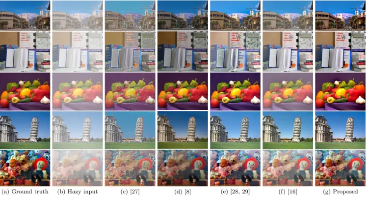
Fig. 8 Haze removed images of various methods where inputs are sythetic hazy images. The top image is ours, peppers image is from MATLAB, tower image is public domain, and others are popular test images used in various papers.
Table 5 Quantitative comparison (PSNR).
Method street books peppers tower toys Average
[27] 16.29 16.57 16.59 18.82 12.56 16.17
[8] 20.12 13.52 29.21 19.32 18.46 20.13
[28],[29] 20.01 15.84 26.73 21.88 17.56 20.40
[16] 19.20 23.59 12.66 23.31 11.42 18.04
Proposed 20.40 21.92 24.78 24.44 18.17 21.94
performance with various state-of-the-art dehazing methods.
Synthesized hazy images were used, having the respective ground truth images. Figure 8 presents qualitative results obtained from our proposed method compared with [27], [8], [28], [29]and[16]. As can be observed visually, our proposal is competitive in haze removal performance. The results of Tarel and Hautire[27]have color distortions. The results of Ren et al.[16]retain some elements of haze under heavy haze conditions. Berman et al.[28],[29] produces better results compared to[8],[16],[27], however with some visible color shift in certain images. In He et al.[8], the output images are darker due to the underlying assumptions used in dark channel prior. Our method which is based on [8]model, does not suffer from this darkening characteristic while maintaining high color fidelity. In Table 5, the PSNR values obtained using the results from Fig. 8 are presented.
Table 6 shows the structural similarity metrics (SSIM) using the same dataset presented. The performance evaluation using PSNR and SSIM shown in Tables 5 and 6 reveals that our approach produces better results.
Table 6 Quantitative comparison (SSIM).
Method street books peppers tower toys Average
[27] 0.873 0.825 0.858 0.933 0.687 0.835
[8] 0.943 0.881 0.979 0.950 0.809 0.912
[28],[29] 0.943 0.815 0.978 0.972 0.888 0.919
[16] 0.948 0.968 0.790 0.981 0.672 0.872
Proposed 0.898 0.930 0.959 0.980 0.876 0.929
7. Conclusion
In this paper, a novel architecture supporting both real-time Retinex-based image enhancement and haze removal is pro- posed, with emphasis on low memory requirement and pro- cessing complexity. The FPGA implementation results show that enhancement and haze removal can be implemented us- ing one module, with 1% logic circuits overhead cost. By utilizing layers 5, 4, and 3 in Fig. 3, our proposed architec- ture supports real-time processing of 1,920×1,200 at 60 fps, under optimal conditions at 125 MHz frequency. By im- plementing the constrainti ≤ l, we were able to preserve edges, which otherwise would have suffered from blur effect due to interpolation on smoothed components. Furthermore, by not using an external frame buffer in Fig. 2, our proposed FPGA implementation do not suffer from latency in process- ing real-time feeds. Our design proves to be competitive with state-of-the-art designs, both qualitatively and quantitatively, shown in Tables 4, 5, and 6.
Acknowledgments
The authors would like to thank the GI-CoRE GSB, Hok- kaido University for fruitful discussions. This work is supported in parts by the Ministry of Internal Affairs and Communications for SCOPE Program (185001003). This work is also supported by VLSI Design and Education Cen- ter (VDEC), the University of Tokyo in collaboration with Synopsys, Inc., Cadence Design Systems, Inc., and Mentor Graphics, Inc.
References
[1] R.C. Gonzalez and R.E. Woods, Digital Image Processing, 3rd ed., Prentice-Hall, Upper Saddle River, NJ, USA, 2006.
[2] E.E.H. Land and J.J. McCann, “Lightness and Retinex theory,” J.
Opt. Soc. Am., vol.61, vol.61, no.1, pp.1–11, 1971.
[3] J. McCann, “Lessons learned from Mondrians applied to real im- ages and color gamuts,” Proc. IS&T/SID Color Imaging Conference, pp.1–8, Nov. 1999.
[4] D.J. Jobson, Z.U. Rahman, and G.A. Woodell, “A multi-scale Retinex for bridging the gap between color images and the human observation of scenes,” IEEE Trans. Image Process., vol.6, no.7, pp.965–976, Aug. 1997.
[5] D.J. Jobson, Z. Rahman, and G.A. Woodell, “Properties and perfor- mance of a center/surround Retinex,” IEEE Trans. Image Process., vol.6, no.3, pp.451–462, March 1997.
[6] D. Terzopoulos, “Image analysis using multiglid relaxation meth- ods,” IEEE Trans. Pattern Anal. Mach. Intell., vol.8, no.2, pp.129–
139, March 1986.
[7] C.T. Lin and C.H. Huang, “CNN-based Retinex technology,” Proc.
European Conf. on Circuit Theory and Design (ECCTD’03), pp.69–
72, Sept. 2003.
[8] K. He, J. Sun, and X. Tang, “Single image haze removal using dark channel prior,” IEEE Trans. Pattern Anal. Mach. Intell., vol.33, no.12, pp.2341–2353, Dec. 2011.
[9] Y. Wang and B. Wu, “Improved single image dehazing using dark channel prior,” Proc. Intelligent Computing and Intelligent Systems (ICIS), pp.789–792, Oct. 2010.
[10] H. Tsutsui, H. Nakamura, R. Hashimoto, H. Okuhata, and T. Onoye,
“An FPGA implementation of real-time Retinex video image en- hancement,” Proc. World Automation Congress, Sept. 2010.
[11] C.T. Shen and W.L. Hwang, “Color image enhancement using Retinex with robust envelope,” 2009 16th IEEE International Con- ference on Image Processing (ICIP), pp.3141–3144, Nov. 2009.
[12] F. Guo, Z. Cai, B. Xie, and J. Tang, “Automatic image haze removal based on luminance component,” Proc. International Conference on Wireless Communications Networking and Mobile Computing (WiCOM), pp.1–4, Oct. 2010.
[13] R. Fattal, “Single image dehazing,” Proc. ACM SIGGRAPH, 2008.
[14] S. Marsi and G. Ramponi, “A flexible FPGA implementation for illuminance–reflectance video enhancement,” J. Real-Time Image Process., vol.8, no.1, pp.81–93, 2013.
[15] Y. Shiau, H. Yang, P. Chen, and Y. Chuang, “Hardware implementa- tion of a fast and efficient haze removal method,” IEEE Trans. Circuits Syst. Video Technol., vol.23, no.8, pp.1369–1374, Aug. 2013.
[16] W. Ren, S. Liu, H. Zhang, J. Pan, X. Cao, and M.H. Yang, “Sin- gle image dehazing via multi-scale convolutional neural networks,”
European conference on computer vision, pp.154–169, 2016.
[17] H. Zhang and V.M. Patel, “Densely connected pyramid dehazing network,” CVPR, 2018.
[18] A. Galdran, A. Alvarez-Gila, A. Bria, J. Vazquez-Corral, and M. Bertalmio, “On the duality between retinex and image dehaz- ing,” CVPR 2018, Salt Lake City, USA, 2018.
[19] E.H. Land and J. McCann, “Lightness and Retinex theory,” J. Opt.
Soc. Am., vol.61, no.1, pp.1–11, Feb. 1971.
[20] R. Kimmel, M. Elad, D. Shaked, R. Keshet, and I. Sobel, “A varia- tional framework for Retinex,” Int. J. Comput. Vision, vol.52, no.1, pp.7–23, April 2003.
[21] H. Tsutsui, S. Yoshikawa, H. Okuhata, and T. Onoye, “Halo arti- facts reduction method for variational based realtime Retinex image enhancement,” Proc. 2012 Asia Pacific Signal and Information Pro- cessing Association Annual Summit and Conference, pp.1–6, Dec.
2012.
[22] S.G. Narasimhan and S.K. Nayar, “Vision and the atmosphere,” Int.
J. Comput. Vision, vol.48, no.3, pp.233–254, 2002.
[23] S.G. Narasimhan and S.K. Nayar, “Chromatic framework for vision in bad weather,” Proc. IEEE Conference on Computer Vision and Pattern Recognition (CVPR), pp.598–605, June 2000.
[24] R.T. Tan, “Visibility in bad weather from a single image,” Proc. IEEE Conference on Computer Vision and Pattern Recognition (CVPR), pp.598–605, June 2008.
[25] Y. Ru and G. Tanaka, “Proposal of dehazing method and quanti- tative index for evaluation of haze removal quality,” IEICE Trans.
Fundamentals, vol.E100-A, no.4, pp.1045–1054, April 2017.
[26] D. Kasauka, H. Tsutsui, S. Imai, T. Imagawa, H. Okuhata, and Y. Miyanaga, “Image smoothing in the spatial domain using multigrid conjugate gradient methods based on accelerated iterative shrink- age,” Proc. Asia-Pacific Signal and Information Processing Associa- tion Annual Summit and Conference (APSIPA), pp.1–5, Dec. 2016.
[27] J. Tarel and N. Hautiére, “Fast visibility restoration from a single color or gray level image,” 2009 IEEE 12th International Conference on Computer Vision, pp.2201–2208, Sept. 2009.
[28] D. Berman, T. Treibitz, and S. Avidan, “Non-local image dehaz- ing,” IEEE Conference on Computer Vision and Pattern Recognition (CVPR), pp.1674–1682, June 2016.
[29] D. Berman, T. Treibitz, and S. Avidan, “Air-light estimation using haze-lines,” IEEE International Conference on Computational Pho- tography (ICCP), pp.1–9, May 2017.
[30] B. Zhang and J. Zhao, “Hardware implementation for real-time haze removal,” IEEE Trans. Very Large Scale Integr. (VLSI) Syst., vol.25, no.3, pp.1188–1192, March 2017.
Dabwitso Kasauka received his B.E. degree in Electrical and Electronic Engineering from University of Zambia in 2012, and his master degree in Information Science and Technology from Hokkaido University in 2015. Presently, he is a doctor course student at Division of Media and Network Technologies, Graduate School of Information Science and Technology, Hokkaido University.
Kenta Sugiyama received his B.E. degree in Electronics and Information Engineering and his master degree in Information Science and Technology, both from Hokkaido University in 2016 and 2018, respectively.
Hiroshi Tsutsui received his B.E. degree in Electrical and Electronic Engineering and his master and Ph.D. degrees in Communications and Computer Engineering from Kyoto Univer- sity in 2000, 2002, and 2005, respectively. He is currently an associate professor in Division of Media and Network Technologies, Hokkaido University. His research interests include cir- cuits and systems for image processing and VLSI design methodology. He is a member of IEEE, ACM, IPSJ, IEEJ, and IIEEJ.
Hiroyuki Okuhata received his B.E., M.E., and Ph.D. degrees in information systems en- gineering from Osaka University in 1995, 1997, and 1999, respectively. He joined Synthesis Cor- poration in 1999 and is currently a senior general manager of Soliton Systems K.K. He has been working on the implementation of application specific hardware, especially in the field of dig- ital image processing.
Yoshikazu Miyanaga is a professor of Grad- uate School of Information Science and Tech- nology, Hokkaido University and the director of Global Station for Big Data and Cyberse- curity, Global Institution for Collaborative Re- search and Education, Hokkaido University. He is also the adjunct professors of University of Technology Sydney (UTS) and King Mongkut’s University of Technology Thonburi (KMUTT).
He was an associate editor of Journal of Signal Processing, RISP Japan (2005–2018). He was a chair of Technical Group on Smart Info-Media Systems, IEICE (IEICE TG-SIS) (2004–2006) and he is now a member of the advisory committee, IEICE TG-SIS (2006–present). He was the President, IEICE Engineering Science (ES) Society (2015–2016) and now an auditor of IEICE (2018–
present). He is a fellow member of IEICE. He was a distinguished lecture (DL) of IEEE CAS Society (2010–2011), an associate editor of IEEE CAS Transaction on TCAS-II (2011–2013), and a Board of Governor (BoG) of IEEE CAS Society (2011–2013).