000001AX
OB NO.002-21048-2
1009
MD 40B
2
MD 40B
2
50B
2
PARTS LIST
MD 40B2/50B2
Website :
50B
2
PARTS
CATALOG
トーハツ船外機
パーツ カタログ
PARTS CATALOG
〒174-0051
〒812-0892
〒530-0043
〒174-0051
03(3966)3116
092(411)8770
06(6358)2971
03(3966)2222
東京都板橋区小豆沢3-5-4
福岡市博多区東那珂2-10-55
大 阪 市 北 区 天 満 1 - 8 - 2 7
東京都板橋区小豆沢3-5-4
本
社
マリン九州
マリン関西
マリン関東
000001AX~
1. This Parts Catalog provides information available as of the end of January, 2010.
2. Please keep the Parts Catalog updated each time when receiving the Service Bulletin describing
the addition, abolition and/or change of parts.
3. Actual shapes of parts may be different from the illustrations shown in this Parts Catalog because
they are described only as a guide for searching parts.
4. One illustration is given more than one article number. Please confirm the sub-number and
applicable model before ordering parts.
5. Given mark in (*) to part number shows assembly or kit part.
6. Marks in this Parts Catalog show.
STD : Standard
OPT : Optional Parts
O/S : Over size
Ass'y : Assembly
AR : As required
EU : European Union
7. Attention to order
Please order painted parts in accordance with following.
The parts that fourth figure of the parts number is (B), (Q) have painted. Present coloring of
power head is black (B) and lower unit is aqua marine blue (Q).
[Example]
Engine Short Block Kit
Lower Unit Assy (L)
3GFB87090-1
3T5Q87302-3
┃
┃
B: Black
Q: Aquamarine Blue
8. About dimensional identification of bolts, nuts and washers.
Bolt
○○○○○○ - ○○○○
Length below neck
Diameter
Nuts & Washers
○○○○○○ - ○○○○
Diameter
9. Hose, that is a standard part, is replaced with long hose.
Part No. Description D30B2 D40B2 D50B2 Remarks
Ref. No.
Qty
7-17 3C8-05221-0 Throttle Limiter Rod 3.5-56 1 1 1 for “F” Type
7-18 3C8-05223-0 Rod Snap B 3.5-4 2 2 2 for “F” Type
7-19 1 3GF-10100-0 Throttle Body A'ssy 1 50ps mark 3GF
7-19 2 3GG-10100-0 Throttle Body A'ssy 1 40ps mark 3GG
7-19 3 3GM-10100-0 Throttle Body A'ssy 1 30ps mark 3GM
7-20 3T5-63718-0 Throttle Cam 1 1 1 7-21 3T5-63721-0 Bushing 6-24-7ブッシング 6-24-7 1 1 1 7-22 910103-6618 Boltボルト 1 1 1 7-23 346-67115-0 Washer 6.5-21-1ワッシャ 6.5-21-1 1 1 1 7-24 346-05228-1 Ball Joint Bボールジョイント B 1 1 1 7-25 930203-0600 Nutナット 1 1 1 7-26 940103-0600 Washerワッシャ 1 1 1 7-27 3T5-10110-0 TPS A'ssyTPSアッシ 1 1 1 7-28 3T5-10107-0 * Rubber Mount* ラバーマウント 3 3 3 7-29 3T5-10128-0 Collar 4.2-6-10.5カラー 4.2-6-10.5 3 3 3 7-30 921503-6420 Screwスクリュ 3 3 3 7-31 3T5-10129-0 Washer 4.2-12.5-0.8ワッシャ 4.2-12.5-0.8 3 3 3
7-32 98AB-30-310 Hoseホース 1 1 1 98AB-3-1000
7-33 3T5-84398-0 Band Lead Wire 104バンドリードワイヤ 104 1 1 1
7-34 338-01133-0 Clip φ7クリップ φ7 1 1 1
7-35 3T5-10104-0 Gasket Throttle Bodyガスケット スロットルボディ 1 1 1
7-36 3T5-02241-0 Bolt 6-25 Precoatedボルト 6-25プレコート 2 2 2
7-37 3T5-72195-0 TPS DecalTPSデカール 1 1 1
Applicable model
Different specification
Illustration position number
Fig. No.
エアチャンバ
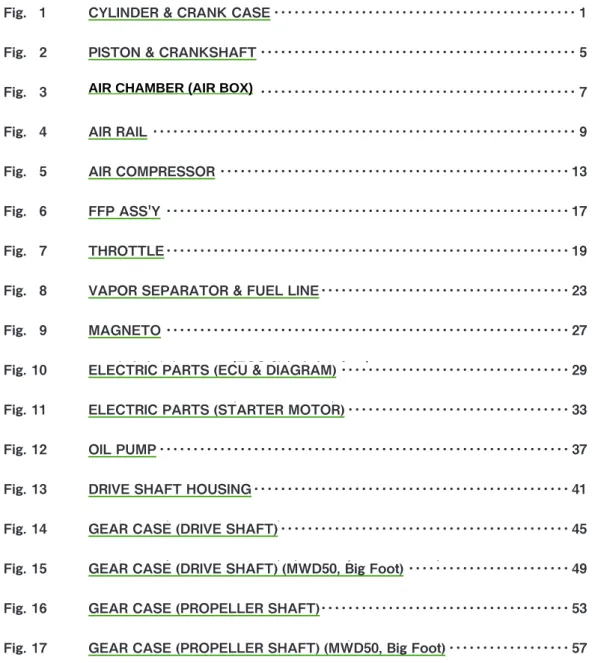
Fig. 3
AIR
・・・・・・・・・・・・・・・・・・・・・・・・・・・・・・・・・・・・・・・・・・・・・・・ 7
エアレール
Fig. 4
AIR RAIL ・・・・・・・・・・・・・・・・・・・・・・・・・・・・・・・・・・・・・・・・・・・・・・・・・・・・・・・・・・・・・・・ 9
エアコンプレッサ
Fig. 5
AIR COMPRESSOR ・・・・・・・・・・・・・・・・・・・・・・・・・・・・・・・・・・・・・・・・・・・・・・・・・・・・ 13
FFP アッシ
Fig. 6
FFP ASS'Y ・・・・・・・・・・・・・・・・・・・・・・・・・・・・・・・・・・・・・・・・・・・・・・・・・・・・・・・・・・・・ 17
スロットル
Fig. 7
THROTTLE ・・・・・・・・・・・・・・・・・・・・・・・・・・・・・・・・・・・・・・・・・・・・・・・・・・・・・・・・・・・・ 19
ベーパセパレータ & フュエルライン
Fig. 8
VAPOR SEPARATOR & FUEL LINE ・・・・・・・・・・・・・・・・・・・・・・・・・・・・・・・・・・・・・ 23
マグネト
Fig. 9
MAGNETO ・・・・・・・・・・・・・・・・・・・・・・・・・・・・・・・・・・・・・・・・・・・・・・・・・・・・・・・・・・・・ 27
エレクトリックパーツ(ECU & ダイヤフラム)
Fig. 10
ELECTRIC PARTS (ECU & DIAGRAM) ・・・・・・・・・・・・・・・・・・・・・・・・・・・・・・・・・・ 29
エレクトリックパーツ(スタータモータ)
Fig. 11
ELECTRIC PARTS (STARTER MOTOR) ・・・・・・・・・・・・・・・・・・・・・・・・・・・・・・・・・ 33
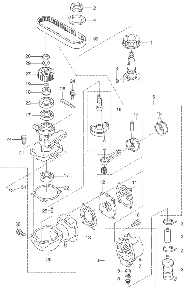
オイルポンプ
Fig. 12
OIL PUMP ・・・・・・・・・・・・・・・・・・・・・・・・・・・・・・・・・・・・・・・・・・・・・・・・・・・・・・・・・・・・・ 37
ドライブシャフトハウジング
Fig. 13
DRIVE SHAFT HOUSING ・・・・・・・・・・・・・・・・・・・・・・・・・・・・・・・・・・・・・・・・・・・・・・・ 41
ギヤケース(ドライブシャフト)
Fig. 14
GEAR CASE (DRIVE SHAFT) ・・・・・・・・・・・・・・・・・・・・・・・・・・・・・・・・・・・・・・・・・・・ 45
ギヤケース(ドライブシャフト)(MWD50, ビッグフット)
Fig. 15
GEAR CASE (DRIVE SHAFT) (MWD50, Big Foot) ・・・・・・・・・・・・・・・・・・・・・・・・ 49
ギヤケース(プロペラシャフト)
Fig. 16
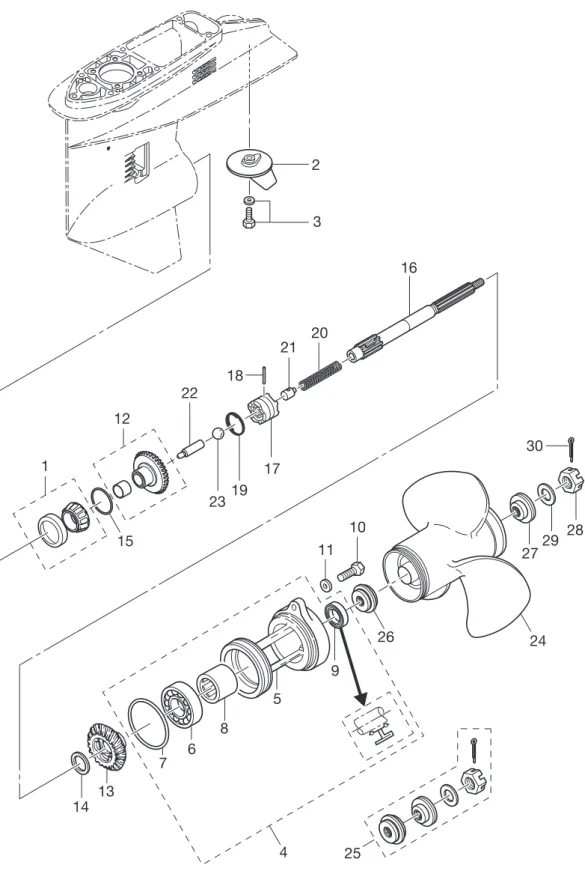
GEAR CASE (PROPELLER SHAFT) ・・・・・・・・・・・・・・・・・・・・・・・・・・・・・・・・・・・・・ 53
ギヤケース(プロペラシャフト)(MWD50, ビッグフット)
Fig. 17
GEAR CASE (PROPELLER SHAFT) (MWD50, Big Foot) ・・・・・・・・・・・・・・・・・・ 57
ブラケット(1)マニュアルチルト
Fig. 18
BRACKET (1) MANUAL TILT ・・・・・・・・・・・・・・・・・・・・・・・・・・・・・・・・・・・・・・・・・・・ 61
マニュアルチルト(M タイプ)
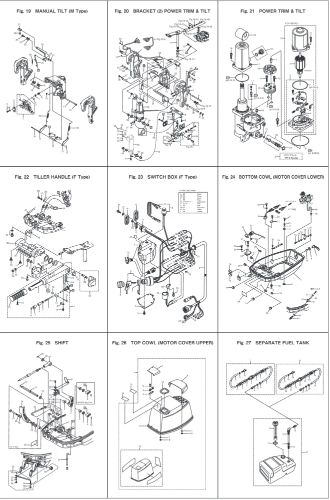
Fig. 19
MANUAL TILT (M Type) ・・・・・・・・・・・・・・・・・・・・・・・・・・・・・・・・・・・・・・・・・・・・・・・・ 65
ブラケット(2)パワートリム & チルト
Fig. 20
BRACKET (2) POWER TRIM & TILT ・・・・・・・・・・・・・・・・・・・・・・・・・・・・・・・・・・・・・ 67
パワートリム & チルト
Fig. 21
POWER TRIM & TILT ・・・・・・・・・・・・・・・・・・・・・・・・・・・・・・・・・・・・・・・・・・・・・・・・・・ 73
ティラハンドル(F タイプ)
Fig. 22
TILLER HANDLE (F Type) ・・・・・・・・・・・・・・・・・・・・・・・・・・・・・・・・・・・・・・・・・・・・・・ 75
スイッチボックス(F タイプ)
Fig. 23
SWITCH BOX (F Type) ・・・・・・・・・・・・・・・・・・・・・・・・・・・・・・・・・・・・・・・・・・・・・・・・・ 79
ボトムカウル(モータカバーロワ)
CONTENTS
AIR CHAMBER (AIR BOX)
Fig. 2
PISTON & CRANKSHAFT ・・・・・・・・・・・・・・・・・・・・・・・・・・・・・・・・・・・・・・・・・・・・・・・ 5
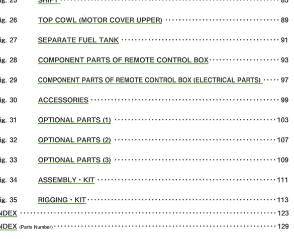
Fig. 25
SHIFT ・・・・・・・・・・・・・・・・・・・・・・・・・・・・・・・・・・・・・・・・・・・・・・・・・・・・・・・・・・・・・・・・・ 85
トップカウル(モータカバーアッパ)
Fig. 26
TOP COWL (MOTOR COVER UPPER) ・・・・・・・・・・・・・・・・・・・・・・・・・・・・・・・・・・ 89
セパレートフュエルタンク
Fig. 27
SEPARATE FUEL TANK ・・・・・・・・・・・・・・・・・・・・・・・・・・・・・・・・・・・・・・・・・・・・・・・ 91
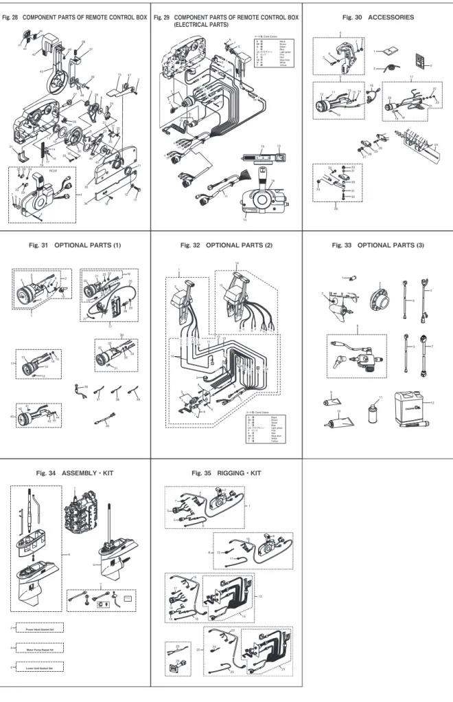
リモコンボックス構成部品
Fig. 28
COMPONENT PARTS OF REMOTE CONTROL BOX ・・・・・・・・・・・・・・・・・・・・・ 93
リモコンボックス構成部品(電装品関係)
Fig. 29
COMPONENT PARTS OF REMOTE CONTROL BOX (ELECTRICAL PARTS) ・・・・・ 97
アクセサリ
Fig. 30
ACCESSORIES ・・・・・・・・・・・・・・・・・・・・・・・・・・・・・・・・・・・・・・・・・・・・・・・・・・・・・・・・ 99
オプショナルパーツ (1)
Fig. 31
OPTIONAL PARTS (1) ・・・・・・・・・・・・・・・・・・・・・・・・・・・・・・・・・・・・・・・・・・・・・・・・ 103
オプショナルパーツ (2) (P タイプ)
Fig. 32
OPTIONAL PARTS (2) ・・・・・・・・・・・・・・・・・・・・・・・・・・・・・・・・・・・・・・・・・・・・・・・・ 107
オプショナルパーツ (3)
Fig. 33
OPTIONAL PARTS (3) ・・・・・・・・・・・・・・・・・・・・・・・・・・・・・・・・・・・・・・・・・・・・・・・・ 109
アッセンブリキット
Fig. 34
ASSEMBLY・KIT ・・・・・・・・・・・・・・・・・・・・・・・・・・・・・・・・・・・・・・・・・・・・・・・・・・・・・ 111
リギングキット
Fig. 35
RIGGING・KIT ・・・・・・・・・・・・・・・・・・・・・・・・・・・・・・・・・・・・・・・・・・・・・・・・・・・・・・・・ 113
索引・・・・・・・・・・・・・・・・・・・・・・・・・・・・・・・・・・・・・・・・・・・・・・・・・・・・・・・・・・・・・・・・・・・・・・・・・・・・・・・ 115
INDEX ・・・・・・・・・・・・・・・・・・・・・・・・・・・・・・・・・・・・・・・・・・・・・・・・・・・・・・・・・・・・・・・・・・・・・・・・・・・・ 123
INDEX
(Parts Number)・・・・・・・・・・・・・・・・・・・・・・・・・・・・・・・・・・・・・・・・・・・・・・・・・・・・・・・・・・・・・・・・・・ 129
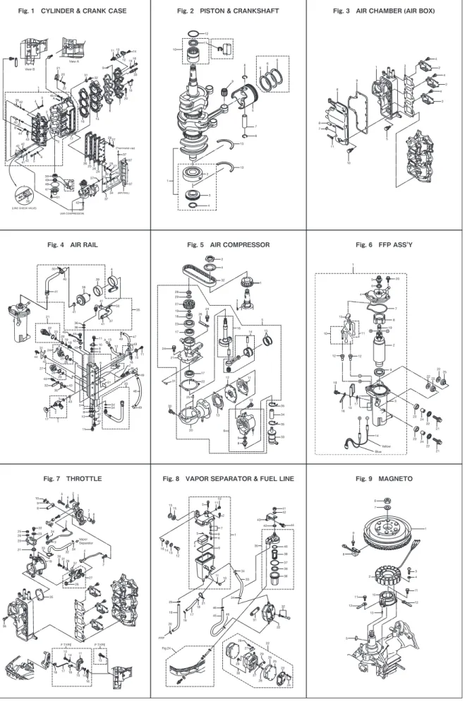
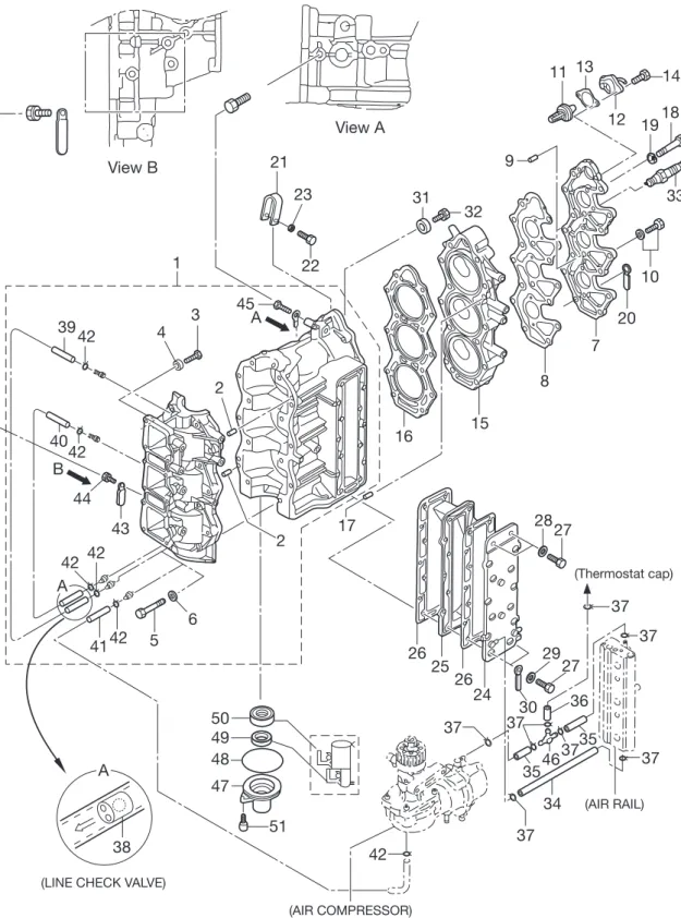
Fig. 1 CYLINDER & CRANK CASE Fig. 2 PISTON & CRANKSHAFT Fig. 3 AIR CHAMBER (AIR BOX)
Fig. 4 AIR RAIL Fig. 5 AIR COMPRESSOR Fig. 6 FFP ASS'Y
Fig. 7 THROTTLE Fig. 8 VAPOR SEPARATOR & FUEL LINE Fig. 9 MAGNETO
(AIR RAIL) (Thermostat cap)
(AIR COMPRESSOR) (LINE CHECK VALVE)
A A 51 38 1 21 23 22 31 32 9 44 43 3942 4 3 11 13 14 121918 33 10 20 7 8 15 16 17 2 6 2 4042 42 42 4142 5 50 49 48 47 42 37 37 37 37 37 27 29 30 36 35 3546 37 37 34 24 26 25 26 2827 45 View B View A B A シリンダー・クランクケース Fig.1 CYLINDER・CRANK CASE
5 11 9 10 12 6 6 6 8 7 8 13 13 2 3 4 1 ピストン・クランクシャフト Fig.2 PISTON・CRANK SHAFT
6 2 2 2 4 4 4 5 7 8 11 10 9 1 3 エアチャンバ( エアボックス) Fig.3 AIR CHAMBER(AIR B OX)
40 41 50 41 38 39 4 35 37 41 41 36 36 22 21 20 23 19 18 44 42 43 11 10 8 9 13 49 47 49 12 24 31 44 43 A A 27 28 29 44 43 32 30 25 26 51 746 1511 13 49 48 33 49 34 34 5 9 8 10 11 42 43 44 43 3 2 17 1 16 6 50 45 エアレール Fig.4 AIR RAIL
2 4 32 1 3 5 16 14 15 24 26 28 29 27 19 18 23 17 24 21 31 30 25 17 22 20 6 13 12 11 10 35 34 35 33 9 7 8 エアコンプレッサ Fig.5 AIR COMPRESSOR
20 7 8 19 2 11 13 5 6 4 12 12 9 3 14 Yellow Blue 18 23 24 22 21 23 24 22 21 1615 17 22 25 2225 1 10 FFP アッシ Fig.6 FFP ASS'Y 13 P TYPE F TYPE 5 6 2 2 2 1 7 6 10 9 8 3 24 22 23 25 26 20 21 33 34 32 4 27 29 37 3031 19 35 36 12 14 11 28 Vapor Separator スロットル Fig.7 THROTTLE 13 15 16 14 13 12 1 10 11 3 2 7 8 6 9 5 4 11 10 41 42 42 43 44 35 40 38 37 39 36 20 19 20 17 18 21 18 33 34 FFP Fig.24 34 32 31 22 22 28 27 29 29 26 25 45 46 46 ベーパセパレータ&フュエルライン Fig.8 VAPOR SEPARATOR & FUEL LINE
6 7 1 9 8 3 4 11 10 12 11 12 13 5 2 マグネト Fig.9 MAGNETO
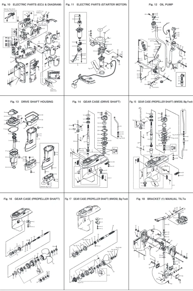
Fig. 13 DRIVE SHAFT HOUSING Fig. 14 GEAR CASE (DRIVE SHAFT) Fig. 15 GEAR CASE (PROPELLER SHAFT) (MWD50, Big Foot)
Fig. 16 GEAR CASE (PROPELLER SHAFT) Fig. 17 GEAR CASE (PROPELLER SHAFT) (MWD50, Big Foot) Fig. 18 BRACKET (1) MANUAL TILTa
ボトムカウル Bottom Cowl 3435 31 33 25 43 Battery(+) Manual, Gas shock
バッテリー(+) Starter Moter(+) スタータモータ(+) 30 30 43 2626 39 40 41 42 21 26 23 36 38 37 14 11 16 14 11 8 19 18 3 5 3 5 23 4 6 20 21 22 24 2 3 1 74 6 9 16 44 45 10 12 13 13 29 EM MAT MAP 32 マニュアル、ガスショック 28 27 1514 17 16 Fig.10 30 6 4 10 11 12 13 15 22 21 20 19 18 14 17 16 9 8 2 3 5 1 7 23 27 24 26 27 29 28 31 9 25
Fig.11 ELECTRIC PARTS(STARTER MOTOR)
(#3 AIR BOX) (#2 AIR BOX) (#1 AIR BOX) (Air Compressor) 46 4344 44 45 38 15 15 14 13 27 30 29 28 31 3335 36 33 34 32 26 34 32 36 33 35 37 15 33 42 41 40 39 8 7 22 15 24 24 18 25 25 12 19 24 Fig.7 17 25 12 25 16 24 9 11 10 6 5 24 20 25 12 25 24 21 25 25 12 23 24 24 1 2 3 4 Fig.12 OIL PUMP MWD50 (Big Foot) 19 18 13 12 19 18 16 17 17 10 12 13 29 6 28 30 3 6 1 4 5 2 31 32 11 9 7 8 27 24 25 2623 22 21 20 14 15 ドライブシャフトハウジング Fig.13 DRIVE SHAFT HOUSING
41 40 38 39 37 36 35 33 14 14 12 34 17 15 13 34 32 2 1 56 3 4 9 8 7 42 4 3 11 10 31 30 22 23 23 44 43 45 Fig.13-20 25 25 27 26 28 16 19 18 29 21 24 20 ギヤケース(ドライブシャフト ) Fig.14 GEAR CASE (DRAIVE SHAFT)
45 24 32 10 8 9 34 35 33 14 31 28 29 30 11 12 1 5 3 4 37 36 2 29 27 39 38 20 19 20 41 40 42 Fig.13-20 Fig.14-24 Fig.14-25 Fig.14-25 25 17 Fig.14 Fig.14 Fig.14 Fig.14 15 16 23 21 22 13 18 6 7 ギヤケース( ドライブシャフト )
Fig.15 GEAR CASE (DRAIVE SHAFT) (Big Foot)
ギヤケース( プロペラシャフト ) Fig.16 GEAR CASE (PROPELLER SHAFT)
25 26 24 11 10 9 5 8 6 7 13 14 2729 28 30 1 12 22 23 15 4 19 17 18 2120 16 3 2 ギヤケース( プロペラシャフト )
Fig. 17 GEAR CASE (PROPELLER SHAFT) (Big Foot)
14 15 8 7 9 10 24 11 25 23 17 16 18 19 21 20 13 12 Fig.16-23 Fig.16-30 Fig.16-28 Fig.16-29 Fig.16-15 Fig.16-6 Fig.16-15 22 1 4 5 2 6 3 40 42 43 45 44 41 39 20 22 21 51 47 12 9 1415 3 5 4 2 17 18 6 1 11 10 13 26 Fig.20-11 46 36 49 29 28 34 33 25 50 27 35 32 36 35 31 52 53 7 10 8 12 16 37 38 19 23 24 30 48 48 ブラケット (1 )マニュアルチルト Fig.18 BRACKET(1)MANUAL TI LT
Fig. 19 MANUAL TILT (M Type) Fig. 20 BRACKET (2) POWER TRIM & TILT Fig. 21 POWER TRIM & TILT
Fig. 22 TILLER HANDLE (F Type) Fig. 23 SWITCH BOX (F Type) Fig. 24 BOTTOM COWL (MOTOR COVER LOWER)
Fig. 25 SHIFT Fig. 26 TOP COWL (MOTOR COVER UPPER) Fig. 27 SEPARATE FUEL TANK
27 20 24 23 26 18 28 2221 25 8 9 10 3 76 15 19 19 15 14 1 2 4 5 16 11 13 1217 A A マニュアルチルト( Mタイプ) Fig.19 MANUAL TI LT(M Type) Fig.18-40 Fig.18-42 Fig.18-43 Fig.18-41 Fig.18-45 Fig18-44 Fig.18-15 Fig.18-9 Fig.18 Fig.18 Fig.18-12 Fig.18-39 Fig.33-6 54 53 7 10 1 50 14 42 4139 36 37 33 35 34 35 45 23 21 8 52 51 16 22 12 22 13 13 15 17 12 48 49 47 46 4 9 38 39 41 42 25 5 15 18 17 24 112 3 6 30 31 32 35 36 27 19 34 33 20 55 56 4039 39 28 29 27 30 31 31 32 39 44 43 4039 26 A A B B ブラケット(2 )パワートリム&チルト (新) Fig.20 BRACKET(2)POWER TRIM & TI LT(New)
Armature Breaker 5 (ø2-55.5) 24 (ø2-52.5) (ø1.5-3.5) (ø1.5-6.5) # 011601XC~ 1 19 7 23 18 17 16 14 2 13 11 10 21 20 22 8 9 15 24 24 3 4 6 12 (ø1.8-69.6) 24 Oリングセット PTT O-Ring Set 24 パワートリム&チルト (新) Fig.21 POWER TRIM & TI LT(New)
26 2728 25 40 32 41 39 23 30 31 33 18 19 17 36 22 21 29 16 35 34 8 2 151213 24 2420 38 37 14 9 10 1 11 3 7 4 5 6 A B A B ティラハンド ル(F タイプ ) Fig.22 TILLER HANDLE(F Type)
P BRBR BB SB 26 R R R 25 YGL 21 R Y WGG 24 3 2 18 19 20 7 5 4 6 1 10 23 12 13 11 14 15 17 16 9 8 22 B :黒 Black BR :茶 Brown G :緑 Green L :青 Blue LG :ライトグリーン Light green P :ピンク Pink R :赤 Red SB :空 Skya blue W :白 White Y :黄 Yellow コード色 Cord Colors R スイッチボックス(F タイプ) Fig.23 SWITCH B OX(F Type)
F TYPE 22 21 4 5 3 2 40 39 47 46 45 11 8 12 14 15 13 7 9 10 1 2 28 23 24 20 19 19 38 17 26 16 18 6 34 36 35 27 25 37 32 31 33 30 29 メインハーネス 42 44 47 47 43 41 燃料フィルタ ボトムカウル( モーターカバーロワ) Fig.24 BOTTOM COWL(MOTOR COVER LOWER)
For F Type 40 29 28 25 8 12 11 13 9 10 7 6 ※ P 1枚 F 3枚 2 1 MWD50 (Big Foot) 5 2 3 4 12 15 17 16 16 22 21 14 24 2630 30 27 19 18 2123 2023 31 39 35 32 Q'ty 1 Q'ty 3 A A A シフト Fig.25 SHIFT 1 15 14 6 4 5 12 3 9 10 11 8 7 13 2 トップカウル( モーターカバーアッパ) Fig.26 TOP COWL(MOTOR COVER UPPER)
12 10 11 6 11 2 5 5 4 3 11 911 8 7 16 15 13 14 17 18 24 2928 29 29 27 21 23 2322 20 25 26 29 19 1 セパレートフュエルタンク Fig.27 SE PARATE FUEL TANK
(ELECTRICAL PARTS)
Fig. 31 OPTIONAL PARTS (1) Fig. 32 OPTIONAL PARTS (2) Fig. 33 OPTIONAL PARTS (3)
Fig. 34 ASSEMBLY・KIT Fig. 35 RIGGING・KIT 44 44 41 42 40 38 37 RC5F 43 39 27 48 328 8 24 15 47 2 2122 20 23 26 11 10 31 14 16 17 19 3332 30 9 21 46 45 35 11 12 13 18 36 34 29 29 25 25 7 65 4 1 25 F N R 6 7 5 3R R R P SB Y G R RL BB BR BR R P W YG B SB 4 12 8 1 2 10 9 15 13 16 14 11 17 B :黒 Black BR :茶 Brown G :緑 Green L :青 Blue LG :ライトグリーン Light green P :ピンク Pink R :赤 Red SB :空 Skya blue W :白 White Y :黄 Yellow コード色 Cord Colors 17 20 22 23 21 18 19 3 5 6 7 8 9 4 12 11 13 15 14 16 10 26 2825 27 29 33 34 33 31 30 31 32 24 1 2 Fig.30 ACCESSORIES 41 42 40 43 4544 12 14 1615 11 13 36 38 39 37 46 31 32 33 30 34 35 27 29 19 2426 20 2123 22 18 25 26 28 17 10 4 5 97 6 9 8 2 1 3 オプショナルパーツ(1 ) Fig.31 OPTIONAL PARTS(1) G G A RR R R R BRBB BR L Y A G PSB R GLR GL GG GG G L P SB R R G G G G 2 10 8 3 4 7 6 8 7 13 11 9 12 15 1 14 5 B :黒 Black BR :茶 Brown G :緑 Green L :青 Blue LG :ライトグリーン Light green P :ピンク Pink R :赤 Red SB :空 Skya blue W :白 White Y :黄 Yellow コード色 Cord Colors オプショナルパーツ(3 )(P タイプ) Fig.32 OPTIONAL PARTS(3)(P Type)
1 2 8 3 6 4 5 7 9 10 11 12 オプショナルパーツ(4 ) Fig.33 OPTIONAL PARTS(4)
Power Head Gasket Set
Water Pump Repair Kit
Lower Unit Gasket Set
1 6 5 2 3 4 7 アッセンブリ・ キット Fig.34 ASSEMB LY・KIT リ ギング・ キット Fig.35 RIGGING・KIT 4 1 13 20 8 7 3 5 6 2 10 12 11 9 14 21 16 23 15 22 18 19 25 26 17 24