特異な酸化還元挙動を示す π 電子系化合物
Ø 化学反応・構造変化が絡んだ酸化還元
Ø 複数の分子ユニットを含む酸化還元系
骨格変換を伴う酸化還元
ー 1,4-‐ ジチイン系ー
S S
S S
S S
S S
S
S S
S Pb(OAc)
4CF
3CO
2H
54%
S
S S
S S
S S
S -e +e
-e S +e
S S S +.
S S
S S 2+
+ +
S S S
S
TTF2+
-e +e -e
+e
• +
S S S
S
TTF+.
TTF
不安定なジカチオン → 安定なジカチオン
化学酸化による確認
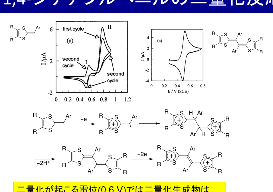
1,4-‐ ジチアフルベニルの二量化反応
二量化が起こる電位 (0.6 V) では二量化生成物は 電極表面で生成すると速やかに酸化される。
S S R R
Ar
S S
R R Ar
R. Carlier et al. / Electrochimica Acta 46 (2001) 3269 – 3277 3271
Scheme 3.
For low scan rate cyclic voltammetry (0.05– 500 V s
−1), the working electrode was either a glassy car- bon disk (0.8 mm diameter Tokai Corporation), a 1 mm diameter gold or platinum disk. They were care- fully polished before each set of voltammograms with 1
! m diamond paste and ultrasonically rinsed in absolute ethanol. Electrochemical instrumentation consisted of a PAR Model 175 Universal programmer and of a home- built potentiostat equipped with a positive feedback compensation device [31]. The data were acquired with a 310 Nicolet oscilloscope.
For high scan rate cyclic voltammetry, the ultrami- croelectrode was a gold or platinum wire (10 ! m diame- ter) sealed in soft glass [32]. The signal generator was a Hewlett – Packard 3314A and the curves were recorded with a 4094 C Nicolet oscilloscope with a minimum acquisition time of 5 ns per point.
Acetonitrile was of Uvasol quality (Merck) and was used as received. The supporting electrolyte NEt
4BF
4and 2,6-lutidine (2,6-dimethylpyridine) were from Fluka (puriss).
Simulations of the voltammograms were made with the BAS Digisim
®simulator 2.1 [33]. Molecular model- ing were performed using the
GAUSSIAN98 [34] pack- age for density functional and solvation calculations.
3. Results and discussion
All the investigated DTF exhibit the same general redox behavior. On the first anodic scan, DTF 3 dis- plays an irreversible oxidation peak (see example DTF 3b, Fig. 1a). A new reversible system is observed at a less positive potential during the following scans. The first electrochemical oxidation (peak II), corresponding to the oxidation of DTF 3 to its cation radical 3 !
+, is followed by a series of chemical reactions leading to 4, which is further oxidized at less positive potentials. The new redox (I) system is associated with the redox behavior of dimer 4 formed in the solution. It is inter- esting to notice that the peak (I) is less than half of the oxidation peak (II) showing that a low quantity of dimer 4 was formed during the scan.
3 . 1 . Mechanism of dimer formation
The electrodimerization reaction involves different electrochemical and chemical steps: homogeneous and heterogeneous electron transfers, carbon – carbon bond formation and elimination of protons. The first oxida- tion step of 3 leads to the formation of the cation-radi- cal that can be observed through the reversibility of its voltammogram (for scan rates higher than 5000 – 10 000 V s
−1, see Fig. 1b). Addition of large amounts of base (2,6-lutidine) to the solution does not change the re- versibility of the fast scan voltammogram indicating that the lifetime of the cation-radical is not modified.
At the lowest scan rates, an increase of the current of the reversible system corresponding to the quantity of produced dimmer is noticed. From these observations, we can conclude that the first reaction step is not a
Fig. 1. Cyclic voltammetry of a solution of 10
−3mol l
−1of DTF 3b (R = p -NCC
6H
4) in acetonitrile ( + 0.2 mol l
−1of NEt4BF
4): (a) on a 1 mm diameter platinum disk electrode, scan rate = 0.2 V s
−1; (b) on 10 !m diameter microelectrode, scan rate = 6000 V s
−1.
R. Carlier et al./Electrochimica Acta 46 (2001) 3269–3277 3273
Fig. 2. Cyclic voltammetry of TTF vinylogues oxidation on a 1 mm Pt electrode in acetonitrile+0.1 mol l−1NEt4BF4. Scan rate:
0.2 V s−1. Temperature=20 °C: (a) 4b (R=p-NCC6H4), concentration=4.5×10⁻⁴ mol l−1; (b) 4f (R=p-MeOC6H4), concen- tration=6×10⁻⁴ mol l−1; (c) 5 (R=H), concentration=8.5×10⁻⁴ mol l−1.
formal potentials (the second electron being more easily removed than the first one). The second noticeable observation is that the inversion of the individual for- mal potentials is larger when a withdrawing group is present on the phenyl ring. Similar trends were found
from the investigations performed in dichloromethane.
The use of this solvent instead of acetonitrile induced an increase of !E° for all the investigated vinylogous TTF as expected from the lower dielectric constant of dichloromethane. In CH2Cl2, depending on the donat- Table 2
Oxidation potentials of TTF vinylogues 4 and 5 assuming fast electron transfers CH2Cl2 CH3CN
R
!E°=E°2−E°1 (V) E°2e− (V) (!Ep in mV)a
!E°=E°2−E°1 (V) E°2e− (V)(!Ep in mV)a
p-NO2C6H4 0.546 (31) −0.065 0.671 (34) −30
4a
p-NCC6H4 0.530 (30)
4b −0.090 0.651 (35) −25
C6H5 0.519 (104)b 76
4d 0.413 (37) −0.013
0.468 (143)b
0.004 104
0.378 (41) p-MeOC6H4
4f
120
p-Me2NC6H4 0.309 (41) 0.004 0.334 (60)c
4g
0.454 (61) 0.467 (92)b
o-NO2C6H4 0.067
4h 0.495 (57)c 221
0.716 (63) 0.551 (57)c
0.079 216
0.519 (109)b o-NCC6H4
4i
0.767 (70)
258
o-MeOC6H4 290 (56)c 0.112 0.293 (59)c
4j
0.551 (63) 402 (59)
0.398 (56)c 181
5 H 0.321 (57)c 0.142
0.436 (57) 0.579 (57)
a!Ep at 0.1 V s−1.
bDouble wave.
cTwo well-separated waves (!Ep=Epa2−Epc1).
S S R
R
Ar
S S R
R
Ar −e S
S R
R
Ar
+ •
S S R
R
Ar
+
S S
R R Ar
+
H
H
− 2H
+S S R
R
Ar
S S
R R Ar
− 2e S
S R
R
Ar
+
S S
R R Ar
+
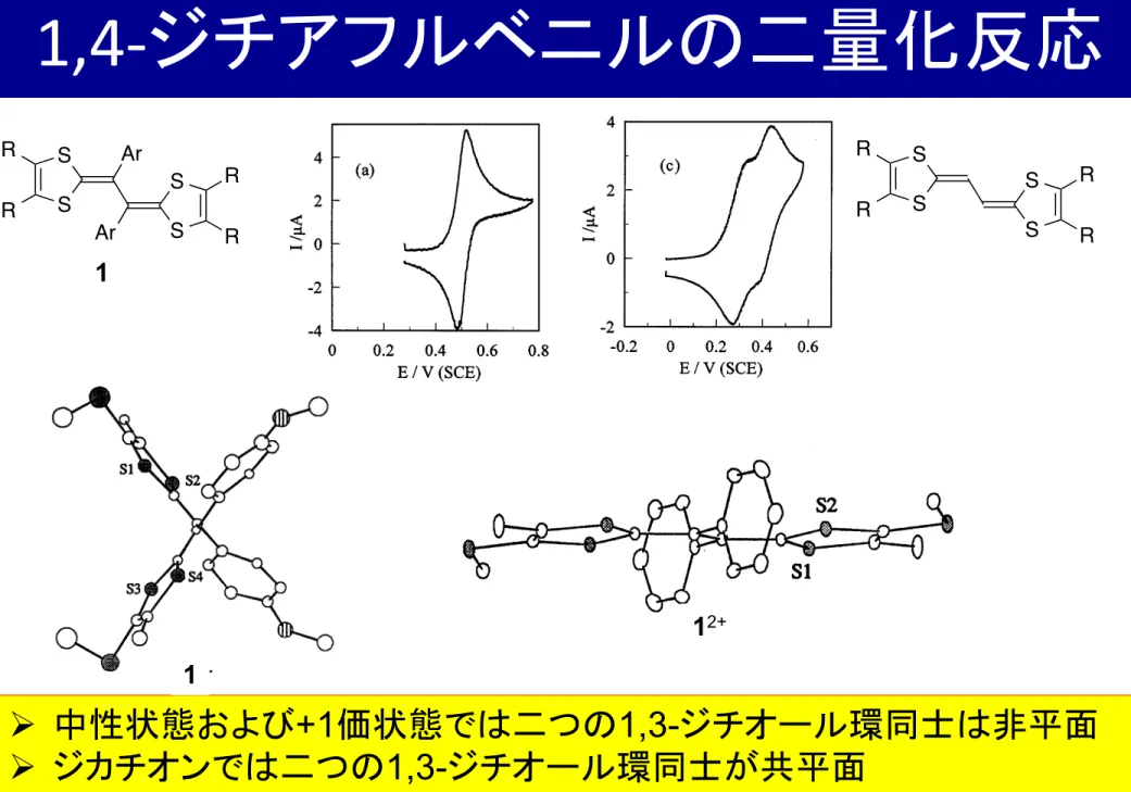
1,4-‐ ジチアフルベニルの二量化反応
Ø 中性状態および +1 価状態では二つの 1,3- ジチオール環同士は非平面 Ø ジカチオンでは二つの 1,3- ジチオール環同士が共平面
→ カチオンラジカルよりもジカチオンの方が安定(= E 1 >E 2 )
R. Carlier et al./Electrochimica Acta 46 (2001) 3269–3277 3273
Fig. 2. Cyclic voltammetry of TTF vinylogues oxidation on a 1 mm Pt electrode in acetonitrile+0.1 mol l−1 NEt4BF4. Scan rate:
0.2 V s−1. Temperature=20 °C: (a) 4b (R=p-NCC6H4), concentration=4.5×10⁻⁴ mol l−1; (b) 4f (R=p-MeOC6H4), concen- tration=6×10⁻⁴ mol l−1; (c) 5 (R=H), concentration=8.5×10⁻⁴ mol l−1.
formal potentials (the second electron being more easily removed than the first one). The second noticeable observation is that the inversion of the individual for- mal potentials is larger when a withdrawing group is present on the phenyl ring. Similar trends were found
from the investigations performed in dichloromethane.
The use of this solvent instead of acetonitrile induced an increase of !E° for all the investigated vinylogous TTF as expected from the lower dielectric constant of dichloromethane. In CH2Cl2, depending on the donat- Table 2
Oxidation potentials of TTF vinylogues 4 and 5 assuming fast electron transfers CH2Cl2 CH3CN
R
!E°=E°2−E°1 (V) E°2e− (V) (!Ep in mV)a
!E°=E°2−E°1 (V) E°2e− (V)(!Ep in mV)a
−30
p-NO2C6H4 0.546 (31) −0.065 0.671 (34)
4a
p-NCC6H4 0.530 (30)
4b −0.090 0.651 (35) −25
C6H5 0.519 (104)b 76
4d 0.413 (37) −0.013
0.468 (143)b
0.004 104
0.378 (41) p-MeOC6H4
4f
p-Me2NC6H4 0.309 (41) 0.004 0.334 (60)c 120 4g
0.454 (61) 0.467 (92)b
o-NO2C6H4 0.067
4h 0.495 (57)c 221
0.716 (63) 0.551 (57)c
0.079 216
0.519 (109)b o-NCC6H4
4i
0.767 (70)
258
o-MeOC6H4 290 (56)c 0.112 0.293 (59)c
4j
0.551 (63) 402 (59)
0.398 (56)c 181
5 H 0.321 (57)c 0.142
0.436 (57) 0.579 (57)
a!Ep at 0.1 V s−1.
bDouble wave.
cTwo well-separated waves (!Ep=Epa2−Epc1).
R. Carlier et al./Electrochimica Acta 46 (2001) 3269–3277 3273
Fig. 2. Cyclic voltammetry of TTF vinylogues oxidation on a 1 mm Pt electrode in acetonitrile+0.1 mol l−1 NEt4BF4. Scan rate:
0.2 V s−1. Temperature=20 °C: (a) 4b (R=p-NCC6H4), concentration=4.5×10⁻⁴ mol l−1; (b) 4f (R=p-MeOC6H4), concen- tration=6×10⁻⁴ mol l−1; (c) 5 (R=H), concentration=8.5×10⁻⁴ mol l−1.
formal potentials (the second electron being more easily removed than the first one). The second noticeable observation is that the inversion of the individual for- mal potentials is larger when a withdrawing group is present on the phenyl ring. Similar trends were found
from the investigations performed in dichloromethane.
The use of this solvent instead of acetonitrile induced an increase of !E° for all the investigated vinylogous TTF as expected from the lower dielectric constant of dichloromethane. In CH2Cl2, depending on the donat- Table 2
Oxidation potentials of TTF vinylogues 4 and 5 assuming fast electron transfers CH2Cl2 CH3CN
R
!E°=E°2−E°1 (V) E°2e− (V) (!Ep in mV)a
!E°=E°2−E°1 (V) E°2e− (V)(!Ep in mV)a
p-NO2C6H4 0.546 (31) −0.065 0.671 (34) −30
4a
p-NCC6H4 0.530 (30)
4b −0.090 0.651 (35) −25
C6H5 0.519 (104)b 76
4d 0.413 (37) −0.013
0.468 (143)b
0.004 104
0.378 (41) p-MeOC6H4
4f
120
p-Me2NC6H4 0.309 (41) 0.004 0.334 (60)c
4g
0.454 (61) 0.467 (92)b
o-NO2C6H4 0.067
4h 0.495 (57)c 221
0.716 (63) 0.551 (57)c
0.079 216
0.519 (109)b o-NCC6H4
4i
0.767 (70)
258
o-MeOC6H4 290 (56)c 0.112 0.293 (59)c
4j
0.551 (63) 402 (59)
0.398 (56)c 181
5 H 0.321 (57)c 0.142
0.436 (57) 0.579 (57)
a!Ep at 0.1 V s−1.
bDouble wave.
cTwo well-separated waves (!Ep=Epa2−Epc1).
R.Carlier et al./Electrochimica Acta46 (2001) 3269–3277 3274
Fig. 3. X-ray investigations: (a) molecular structure of4f(from Ref. [11]); (b) molecular structure of the dicationic vinylogous TTF4d(from Ref. [40]), counteranion: I3−.
donor in CH2Cl2 to an iodine atmosphere, the X-ray structures of several of these donors were determined [22,39,40]. The donor under its cation radical or dica- tionic forms adopts a new conformation with a planar extended TTF core while the substituents are located in a perpendicular plane (Fig. 3). Yamashita et al. ob- served similar conformational modifications on cation radical salts of vinylogous TTF substituted by bulky groups [17]. Interestingly, neutral non-substituted derivatives (R=H), analogues of5, are planar and do not undergo conformational changes upon oxidation as the extended TTF core remains planar.
3.4.Molecular modeling
The crystallographic data support the hypothesis that the unusual redox behavior for the TTF vinylogues is caused by structural changes. More surprisingly is the way that the oxidation potentials separations!E°vary with the substitution. To rationalize the effects, we performed a series of molecular modeling calculations to determine both the geometries and the stabilities of the TTF vinylogues in their three oxidation states.
The geometries were determined by full optimizations of the conformations using the B3LYP density func- tional [41] and the 6-31G* basis set [42] (see Fig. 4). For 5, the neutral, radical cation and dication were found to be planar in agreement with the X-ray structural inves- tigations. For the phenyl-substituted donors4, the neu- tral are twisted and the radical cation and the dication display an almost planar TTF core. The situation changes when a donor group is introduced on the phenyl ring and the dication is not planar anymore.
This change of behavior is explained by a better stabi- lization of the positive charges due to the conjugation with the phenyl ring bearing donor groups. It results in a competition between the stabilization energy brought by the conjugation at the level of the TTF core and the energy gained by the stabilization of the positive charge by the donor groups. In the case of the simple phenyl and, of course, for withdrawing substituents, the dica- tion has a better advantage to make the TTF core planar. It is noticeable that the electronic effects due to the repulsion of the two positive charges are lowered in the presence of the solvent. Therefore, it is likely that the gas phase calculations overestimate the twisting of the TTF core in the charged states.
To discuss the variations of the oxidation potentials more precisely, we should estimate the solvation free energies because much of !G°disp in gas phase has an electrostatic origin. We used the IPCM [43] method where the solvent is described as a dielectric continuum with the geometries previously optimized in gas phase.
2TTF!+"TTF2++TTF, !G°disp
ing properties of the phenyl group the bielectronic waves can split or not into two monoelectronic ones, but the same general effect is observed for all the TTF in both solvents.
When a substituent is introduced on theortho-posi- tion of the phenyl group (4h–j), similar decreases of
!E° are observed as a function of the withdrawing strength of the substituent. However, the extracted!E°
are always larger for the ortho-substituted molecules than for the correspondingpara-substituted molecules.
These analyses were confirmed by spectrovoltamme- try experiments [22]. The spectrum of the electrogener- ated radical-cation was clearly visible before the formation of the dication in the case of the non-substi- tuted derivative 5and in the case of electron donating substituents linked to4. On the contrary, the dication is directly produced during the oxidation in the case of withdrawing substituents.
3.3.X-ray structural in!estigations
The single-crystal X-ray analysis of a neutral donor 4f reveals a non-planar geometry due to steric hin- drance [11]. This severely distorted structure [22,39,40]
was found for all the substituted TTF vinylogues [16– 18]. After a chemical oxidation either with a solution of Cu(ClO4)2·6H2O in THF or by exposing a solution of a
R. Carlier et al./Electrochimica Acta 46 (2001) 3269–3277 3274
Fig. 3. X-ray investigations: (a) molecular structure of4f (from Ref. [11]); (b) molecular structure of the dicationic vinylogous TTF 4d (from Ref. [40]), counteranion: I3−.
donor in CH
2Cl
2to an iodine atmosphere, the X-ray structures of several of these donors were determined [22,39,40]. The donor under its cation radical or dica- tionic forms adopts a new conformation with a planar extended TTF core while the substituents are located in a perpendicular plane (Fig. 3). Yamashita et al. ob- served similar conformational modifications on cation radical salts of vinylogous TTF substituted by bulky groups [17]. Interestingly, neutral non-substituted derivatives (R = H), analogues of 5, are planar and do not undergo conformational changes upon oxidation as the extended TTF core remains planar.
3.4. Molecular modeling
The crystallographic data support the hypothesis that the unusual redox behavior for the TTF vinylogues is caused by structural changes. More surprisingly is the way that the oxidation potentials separations ! E° vary with the substitution. To rationalize the effects, we performed a series of molecular modeling calculations to determine both the geometries and the stabilities of the TTF vinylogues in their three oxidation states.
The geometries were determined by full optimizations of the conformations using the B3LYP density func- tional [41] and the 6-31G* basis set [42] (see Fig. 4). For 5, the neutral, radical cation and dication were found to be planar in agreement with the X-ray structural inves- tigations. For the phenyl-substituted donors 4, the neu- tral are twisted and the radical cation and the dication display an almost planar TTF core. The situation changes when a donor group is introduced on the phenyl ring and the dication is not planar anymore.
This change of behavior is explained by a better stabi- lization of the positive charges due to the conjugation with the phenyl ring bearing donor groups. It results in a competition between the stabilization energy brought by the conjugation at the level of the TTF core and the energy gained by the stabilization of the positive charge by the donor groups. In the case of the simple phenyl and, of course, for withdrawing substituents, the dica- tion has a better advantage to make the TTF core planar. It is noticeable that the electronic effects due to the repulsion of the two positive charges are lowered in the presence of the solvent. Therefore, it is likely that the gas phase calculations overestimate the twisting of the TTF core in the charged states.
To discuss the variations of the oxidation potentials more precisely, we should estimate the solvation free energies because much of ! G °
dispin gas phase has an electrostatic origin. We used the IPCM [43] method where the solvent is described as a dielectric continuum with the geometries previously optimized in gas phase.
2TTF
!+" TTF
2++ TTF, ! G°
disping properties of the phenyl group the bielectronic waves can split or not into two monoelectronic ones, but the same general effect is observed for all the TTF in both solvents.
When a substituent is introduced on the ortho-posi- tion of the phenyl group (4h – j), similar decreases of
! E° are observed as a function of the withdrawing strength of the substituent. However, the extracted ! E ° are always larger for the ortho-substituted molecules than for the corresponding para-substituted molecules.
These analyses were confirmed by spectrovoltamme- try experiments [22]. The spectrum of the electrogener- ated radical-cation was clearly visible before the formation of the dication in the case of the non-substi- tuted derivative 5 and in the case of electron donating substituents linked to 4. On the contrary, the dication is directly produced during the oxidation in the case of withdrawing substituents.
3.3. X -ray structural in!estigations
The single-crystal X-ray analysis of a neutral donor 4f reveals a non-planar geometry due to steric hin- drance [11]. This severely distorted structure [22,39,40]
was found for all the substituted TTF vinylogues [16 – 18]. After a chemical oxidation either with a solution of Cu(ClO
4)
2·6H
2O in THF or by exposing a solution of a S
S R
R
Ar
S S
R R Ar
S S R
R
S S
R R
1
1
1
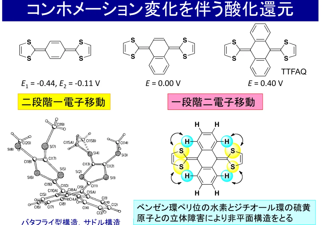
2+コンホメーション変化を伴う酸化還元
一段階二電子移動 二段階一電子移動
S
S S
S S
S S
S S
S S
S
E 1 = -‐0.44, E 2 = -‐0.11 V E = 0.00 V E = 0.40 V
ベンゼン環ペリ位の水素とジチオール環の硫黄 原子との立体障害により非平面構造をとる
S
S S
S H
H H
H
H H
H H
バタフライ型構造,サドル構造
An Introduction to TTFAQ
two days thin red needle-shaped crystals, up to 5 mm in length, were harvested from the anode and submitted for an X-ray crystallographic analysis.
78MeS SMe
svs
54
Bu4NCI04 DCM, rt, 2 days Electrochemical Oxidation
Scheme 7: Electrocrystallisation ofTTFAQ derivative 54.
For comparison, the X-ray crystal structure of neutral 54 is shown in Figure 25.
76The molecule adopts the characteristic saddle-shape, as a consequence of the steric repulsion between the sulfur atoms and the peri-hydrogen atoms.
Figure 25: X-ray crystal structure of neutral 54 possessing the characteristic saddle-shape. One of the methyl groups is disordered over two positions. 79
In the crystal structure of 54
2+(Cl0
4-)2,the anion occupies a general position, while the dication 54
2+ has crystallographic Ci symmetry (Figure 26).
77The conformation of the dication is very different from the saddle-shape of neutral 54. The anthracene moiety is planar and has essentially the geometry of the anthracene molecule,
80that is, it is fully aromatic. The planar 1 ,3-dithiolium rings and the anthracene system form a dihedral angle of 77.2° and are linked through an essentially single bond: C(7)-C(8) 1.490(3) A. The 1 ,3-dithiolium rings in 54
2+ display stronger n-conjugation than in the neutral molecule 54. The C-S bonds in the
27
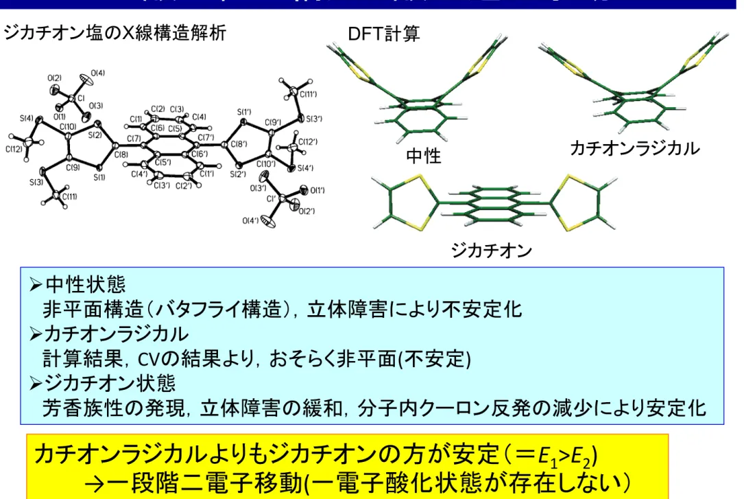
TTFAQ
Ø 中性状態
非平面構造(バタフライ構造),立体障害により不安定化 Ø カチオンラジカル
計算結果, CV の結果より,おそらく非平面 ( 不安定 ) Ø ジカチオン状態
芳香族性の発現,立体障害の緩和,分子内クーロン反発の減少により安定化
酸化種の構造と酸化還元挙動
カチオンラジカルよりもジカチオンの方が安定(= E 1 >E 2 )
→ 一段階二電子移動 ( 一電子酸化状態が存在しない)
cation in its optimized structure. The calculations give 0.14 eV for this energy difference. Whether by calculation or experiment, the inner reorganization for the oxidation of2to its cation radical is quite small.
These calculations confirm that a major structural change occurs upon proceeding from the neutral to the dication. It is not clear whether the greater part of the structural change is associated with the first or with the second electron transfer or whether one of these structural changes is sufficiently small that it is reasonable to assume that it is concerted with electron transfer. Nevertheless, it is reasonable to assume that at least one of the reactions occurs as a two-step process with structural change occurring as a distinct chemical change (isomerization, conformational change, etc.) either preceding or following the electron transfer.
Analysis of the Voltammograms According to Two-Step Processes.In this section, we will determine whether two-step processes can be the basis of a mechanism that will account for the data as effectively as the concerted processes used above.
The mechanism is given as Scheme 1 in which the species labeled
“DC” have structures similar to the structure of the dication,
“CR” species have structures similar to that of the cation radical, and “N” species have structures similar to that of the neutral compound. This mechanism includes two-step processes for both electron transfers with structural change occurring both before and after electron transfer.
One data set obtained at 25°C was analyzed according to Scheme 1, and the best-fit parameters are given in Table 2. The agreement between simulation and data for scan rates from 0.10 to 30.0 V/s was of equal quality to that obtained in the simulations reported in Table 1 wherein the electron transfers and structural changes are considered to be concerted. Comparisons of data
with simulations for both mechanisms for this data set are shown in the Supporting Information.
That equally good fits could be obtained using reactions 1 and 2 compared to Scheme 1 is not surprising in view of the additional array of parameters available in Scheme 1. What is more important is that, where comparisons can be made, there is reasonable agreement between parameters found for both mechanisms. These includeECRo +/N) -0.017 V (Scheme 1, Table 2) andE°1 ) -0.029 V (reaction 1, Table 1),EDCo 2+/CR+) -0.338 V (Scheme 1, Table 2) andE°2) -0.318 V (reaction 2; Table 1),E°ov) -0.178 (Scheme 1; Table 2) and-0.174 (Table 1), and finally, E°1-E°2)0.321 V (Scheme 1) and 0.289 V (Table 1).
The greatest improvement of Scheme 1 over reactions 1 and 2 (in which the structural changes and electron transfer are considered to be concerted) is that allRvalues were 0.50 for Scheme 1 whereas an abnormally low value of 0.25-0.30 was required forR1 when fitting with reactions 1 and 2. Similar healing of deviantRvalues was obtained when Scheme 1 was applied to the oxidation of two bis(dimethylamino)arenes.12Also, according to Scheme 1 the rate constant for the first electron- transfer reaction (NfN•++e-) is large, ca. 2-3 cm/s, which is much more consistent with a reaction having the small inner Figure 6. Optimized structures of neutral2, the cation radical, and
the dication.
Scheme 1
Table 2. Parameters Used in Simulations According to Scheme 1a
parameter
KCR/N 5.5×10⁻⁶
kNfCR 0.9 s-1
kCRfN 1.6×10⁵s-1
KCR+/N+ 1.8×10³ kN+fCR+ 5.1×10⁹s-1 kCR+fN+ 2.9×10⁶s-1 KDC+/CR+ 2.2×10⁻³ kCR+fDC+ 1.1×10⁴s-1 kDC+fCR+ 4.8×10⁶s-1
KDC2+/CR2+ 4.7
kCR2+fDC2+ 90 s-1 kDC2+fCR2+ 19 s-1 EDC2+/DC+
o -0.495
ks, DC2+/DC+ 0.36 cm/s
ECRo 2+/CR+ -0.299 V
ks, CR2+/CR+ 0.030 cm/s
ECRo +/CR -0.328 V
ks,CR+/CR 0.36 cm/s
EN+/N
o 0.175 V
ks,N+/N 2.6 cm/s
EDCo 2+/CR+b -0.338 V ECRo +/Nb -0.017 V
Eoverallo -0.178 V
aPotentials are referred to the formal potential of the ferrocenium/
ferrocene couple. Measurement conditions: 0.77 mM2, 25°C; scan rates simulated: 0.10-30.0 V/s. Values ofRfor all four electron-transfer reactions were set at 0.50. Diffusion coefficient for all species: 5.3× 10⁻⁶cm2/s.bValues calculated from formal potentials and equilibrium constants from analysis according to Scheme 1.
Potential InVersion in Extended TetrathiafulValene Langmuir, Vol. 22, No. 25, 2006 10687
cation in its optimized structure. The calculations give 0.14 eV for this energy difference. Whether by calculation or experiment, the inner reorganization for the oxidation of2to its cation radical is quite small.
These calculations confirm that a major structural change occurs upon proceeding from the neutral to the dication. It is not clear whether the greater part of the structural change is associated with the first or with the second electron transfer or whether one of these structural changes is sufficiently small that it is reasonable to assume that it is concerted with electron transfer. Nevertheless, it is reasonable to assume that at least one of the reactions occurs as a two-step process with structural change occurring as a distinct chemical change (isomerization, conformational change, etc.) either preceding or following the electron transfer.
Analysis of the Voltammograms According to Two-Step Processes.In this section, we will determine whether two-step processes can be the basis of a mechanism that will account for the data as effectively as the concerted processes used above.
The mechanism is given as Scheme 1 in which the species labeled
“DC” have structures similar to the structure of the dication,
“CR” species have structures similar to that of the cation radical, and “N” species have structures similar to that of the neutral compound. This mechanism includes two-step processes for both electron transfers with structural change occurring both before and after electron transfer.
One data set obtained at 25°C was analyzed according to Scheme 1, and the best-fit parameters are given in Table 2. The agreement between simulation and data for scan rates from 0.10 to 30.0 V/s was of equal quality to that obtained in the simulations reported in Table 1 wherein the electron transfers and structural changes are considered to be concerted. Comparisons of data
with simulations for both mechanisms for this data set are shown in the Supporting Information.
That equally good fits could be obtained using reactions 1 and 2 compared to Scheme 1 is not surprising in view of the additional array of parameters available in Scheme 1. What is more important is that, where comparisons can be made, there is reasonable agreement between parameters found for both mechanisms. These includeECR+/N
o ) -0.017 V (Scheme 1, Table 2) and E°1) -0.029 V (reaction 1, Table 1),EDC2+/CR+
o ) -0.338 V (Scheme 1, Table 2) andE°2) -0.318 V (reaction 2; Table 1),E°ov) -0.178 (Scheme 1; Table 2) and-0.174 (Table 1), and finally, E°1-E°2)0.321 V (Scheme 1) and 0.289 V (Table 1).
The greatest improvement of Scheme 1 over reactions 1 and 2 (in which the structural changes and electron transfer are considered to be concerted) is that allRvalues were 0.50 for Scheme 1 whereas an abnormally low value of 0.25-0.30 was required forR1 when fitting with reactions 1 and 2. Similar healing of deviantRvalues was obtained when Scheme 1 was applied to the oxidation of two bis(dimethylamino)arenes.12Also, according to Scheme 1 the rate constant for the first electron- transfer reaction (NfN•++e-) is large, ca. 2-3 cm/s, which is much more consistent with a reaction having the small inner Figure 6. Optimized structures of neutral2, the cation radical, and
the dication.
Scheme 1
Table 2. Parameters Used in Simulations According to Scheme 1a
parameter
KCR/N 5.5×10⁻⁶
kNfCR 0.9 s-1
kCRfN 1.6×10⁵s-1
KCR+/N+ 1.8×10³ kN+fCR+ 5.1×10⁹s-1 kCR+fN+ 2.9×10⁶s-1 KDC+/CR+ 2.2×10⁻³ kCR+fDC+ 1.1×10⁴s-1 kDC+fCR+ 4.8×10⁶s-1
KDC2+/CR2+ 4.7
kCR2+fDC2+ 90 s-1 kDC2+fCR2+ 19 s-1 EDCo 2+/DC+ -0.495
ks, DC2+/DC+ 0.36 cm/s
ECRo 2+/CR+ -0.299 V
ks, CR2+/CR+ 0.030 cm/s
ECRo +/CR -0.328 V
ks,CR+/CR 0.36 cm/s
ENo+/N 0.175 V
ks,N+/N 2.6 cm/s
EDC2+/CR+
o b -0.338 V
ECR+/N
o b -0.017 V
Eoverallo -0.178 V
aPotentials are referred to the formal potential of the ferrocenium/
ferrocene couple. Measurement conditions: 0.77 mM2, 25°C; scan rates simulated: 0.10-30.0 V/s. Values ofRfor all four electron-transfer reactions were set at 0.50. Diffusion coefficient for all species: 5.3× 10⁻⁶cm2/s.bValues calculated from formal potentials and equilibrium constants from analysis according to Scheme 1.
Potential InVersion in Extended TetrathiafulValene Langmuir, Vol. 22, No. 25, 2006 10687
cation in its optimized structure. The calculations give 0.14 eV for this energy difference. Whether by calculation or experiment, the inner reorganization for the oxidation of2to its cation radical is quite small.
These calculations confirm that a major structural change occurs upon proceeding from the neutral to the dication. It is not clear whether the greater part of the structural change is associated with the first or with the second electron transfer or whether one of these structural changes is sufficiently small that it is reasonable to assume that it is concerted with electron transfer. Nevertheless, it is reasonable to assume that at least one of the reactions occurs as a two-step process with structural change occurring as a distinct chemical change (isomerization, conformational change, etc.) either preceding or following the electron transfer.
Analysis of the Voltammograms According to Two-Step Processes.In this section, we will determine whether two-step processes can be the basis of a mechanism that will account for the data as effectively as the concerted processes used above.
The mechanism is given as Scheme 1 in which the species labeled
“DC” have structures similar to the structure of the dication,
“CR” species have structures similar to that of the cation radical, and “N” species have structures similar to that of the neutral compound. This mechanism includes two-step processes for both electron transfers with structural change occurring both before and after electron transfer.
One data set obtained at 25 °C was analyzed according to Scheme 1, and the best-fit parameters are given in Table 2. The agreement between simulation and data for scan rates from 0.10 to 30.0 V/s was of equal quality to that obtained in the simulations reported in Table 1 wherein the electron transfers and structural changes are considered to be concerted. Comparisons of data
with simulations for both mechanisms for this data set are shown in the Supporting Information.
That equally good fits could be obtained using reactions 1 and 2 compared to Scheme 1 is not surprising in view of the additional array of parameters available in Scheme 1. What is more important is that, where comparisons can be made, there is reasonable agreement between parameters found for both mechanisms. These include ECRo +/N) -0.017 V (Scheme 1, Table 2) andE°1 ) -0.029 V (reaction 1, Table 1),EDCo 2+/CR+) -0.338 V (Scheme 1, Table 2) andE°2) -0.318 V (reaction 2; Table 1),E°ov) -0.178 (Scheme 1; Table 2) and-0.174 (Table 1), and finally, E°1-E°2)0.321 V (Scheme 1) and 0.289 V (Table 1).
The greatest improvement of Scheme 1 over reactions 1 and 2 (in which the structural changes and electron transfer are considered to be concerted) is that allRvalues were 0.50 for Scheme 1 whereas an abnormally low value of 0.25-0.30 was required for R1when fitting with reactions 1 and 2. Similar healing of deviantRvalues was obtained when Scheme 1 was applied to the oxidation of two bis(dimethylamino)arenes.12Also, according to Scheme 1 the rate constant for the first electron- transfer reaction (NfN•++e-) is large, ca. 2-3 cm/s, which is much more consistent with a reaction having the small inner Figure 6. Optimized structures of neutral2, the cation radical, and
the dication.
Scheme 1
Table 2. Parameters Used in Simulations According to Scheme 1a
parameter
KCR/N 5.5×10⁻⁶
kNfCR 0.9 s-1
kCRfN 1.6×10⁵s-1
KCR+/N+ 1.8×10³ kN+fCR+ 5.1×10⁹s-1 kCR+fN+ 2.9×10⁶s-1 KDC+/CR+ 2.2×10⁻³ kCR+fDC+ 1.1×10⁴s-1 kDC+fCR+ 4.8×10⁶s-1 KDC2+/CR2+ 4.7
kCR2+fDC2+ 90 s-1 kDC2+fCR2+ 19 s-1 EDCo 2+/DC+ -0.495
ks, DC2+/DC+ 0.36 cm/s
ECRo 2+/CR+ -0.299 V
ks, CR2+/CR+ 0.030 cm/s
ECRo +/CR -0.328 V
ks,CR+/CR 0.36 cm/s
ENo+/N 0.175 V
ks,N+/N 2.6 cm/s
EDCo 2+/CR+b -0.338 V ECR+/N
o b -0.017 V
Eoverallo -0.178 V
aPotentials are referred to the formal potential of the ferrocenium/
ferrocene couple. Measurement conditions: 0.77 mM2, 25°C; scan rates simulated: 0.10-30.0 V/s. Values ofRfor all four electron-transfer reactions were set at 0.50. Diffusion coefficient for all species: 5.3× 10⁻⁶cm2/s.bValues calculated from formal potentials and equilibrium constants from analysis according to Scheme 1.
Potential InVersion in Extended TetrathiafulValene Langmuir, Vol. 22, No. 25, 2006 10687
An Introduction to TTFAQ
dication ["inner" S(l)-C(8) 1.695(2)
A
and S(2)-C(8) 1.672(2)A;
"outer" S(l)-C(9) 1.734(2) and S(2)-C(IO) 1.708(2) A] are contracted compared with neutral 54 with averages 1.767(4)A
and 1.759(5)A
for the "inner" and "outer" C-S bonds, respectively/6 while the C(9)-C(10) bond is lengthened from 1.334(7)A
in 54 to 1.375(3)A
in 542\Cl04-)2.81Figure 26: X-ray crystal structure of 542+(CI04-)2 showing 50% thermal ellipsoids. Primed atoms are generated by the inversion centre. The saddle-shape of neutral 54 is not retained upon oxidation to the dication. 78
The crystal packing of542+(Cl04-h is shown in Figure 27. Interactions ofthe S(l) atom with two perchlorate anions can explain the weakening of the S( 1 )-C bonds in the dithiolium ring compared with the S(2)-C bonds. There are no S"'S contacts significantly shorter than twice the van der Waals radius ofS (3.68
A).
82Figure 27: Crystal packing of 542+(CI04) 2• Shortest intermolecular contacts (in A): S"'O i = 3.335(2), ii = 3.205(2), iii = 3.277(2), iv = 3.157(2); S"'S v = 3.655(1); S"'C vi= 3.450(2).78
28