Mathematical Model of Permanent Magnet Synchronous Motor
Natthawut Kongchoo
†1Phonsit Santiprapan
†1Nattha Jindapetch
†1Abstract: The mathematical model of a permanent magnet synchronous motor (PMSM) is necessary to design the control of PMSM. The mathematical model on three-phase system is not commonly used for the control design. This approach is the time-varying model. Therefore, the control strategy design becomes even more difficult. Owing to this problem, this paper presents the dynamic model of the PMSM using the DQ modeling method. In addition, the proposed model has been validated with the exact topology model in MATLAB/Simulink program.
Keywords: permanent magnet synchronous motor (PMSM); DQ modeling method; model validation
1. Introduction
Nowadays, the PMSM is widely used for many applications, especially for electric vehicle (EV). In order to achieve a high performance PMSM drives, the control of the PMSM drives should be suitably designed. From literature reviews, there are many control techniques (field-oriented control, predictive DTC scheme, nonlinear torque control scheme, etc.) and many estimation techniques (flux vector, speed) [1-3]. The control design of PMSM drives is based on the mathematical model of PMSM. Therefore, the aim of this work is to derive the mathematical model of PMSM. The DQ modeling approach is selected to derive the mathematical model of the studied PMSM. This paper is structured as follows. The principle of the PMSM is briefly explained in Section 2. The mathematical model of the PMSM are presented in Section 3. The model validation is expressed in Section 4. Finally, Section 5 concludes the purpose of this paper.
2. The Principle of the PMSM
The operation of a PMSM is similar to a three-phase induction motor. The three-phase voltage source connected with the stator winding produces a rotating magnetic field (RMF). The RMF cause the rotor to turn. The power losses in the rotor side do not occur because the rotor of PMSM is a permanent magnet. Moreover, this machine can provide a constant torque. The structure and equivalent circuit of the PMSM are shown in Fig. 1.
Va Vb Vc Rs Rs Rs Ls Ls Ls N S N S Magnetic coupling Stator Rotor
Fig. 1 The structure and equivalent circuit of the PMSM
3. Mathematical Model of the PMSM
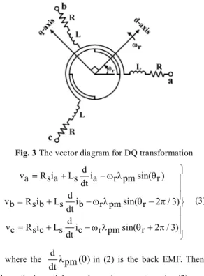
The DQ modeling method is applied to derive a mathematical model of the system as depicted in Fig. 2. The DQ– axis in Fig. 3 is rotated with the angular speed (
r
) by phase shift (
r
). The stator voltages (vabc
) can be written for three-phase system as follows:d
vabc R is abc (L is abc pm( )) dt (1) sin( )r d ( ) sin( 2 / 3) pm r pm r dt sin( r 2 / 3) (2)
†1 Department of Electrical Engineering, Faculty of Engineering, Prince of Songkla University, Hat Yai, Songkhla 90110, Thailand
Fig. 3 The vector diagram for DQ transformation
d va R is a Ls ia r pmsin( )r dt d vb R is b Ls ib r pmsin( r 2 / 3) dt d vc R is c Ls ic r pmsin( r 2 / 3) dt (3) where the
d
pm
( )
dt
in (2) is the back EMF. Then, the mathematical model on three-phase system in (3) can be transformed into the DQ-axis. The dynamic equation of the PMSM on DQ-axis can be written in (4) - (5).d d d vd R is d r q d R is d Ld id r q qL i pm dt dt dt (4)
d
d
v
q
R i
s q
r d
q R i
s q
L
q
i
q
r d d
L i
r pm
dt
dt
(5)As a result, the equivalent circuit of the PMSM in DQ-axis derived by using DQ modeling method is shown in Fig. 4.
R
sL
d r q V
d+
-R
sL
q r d V
q+
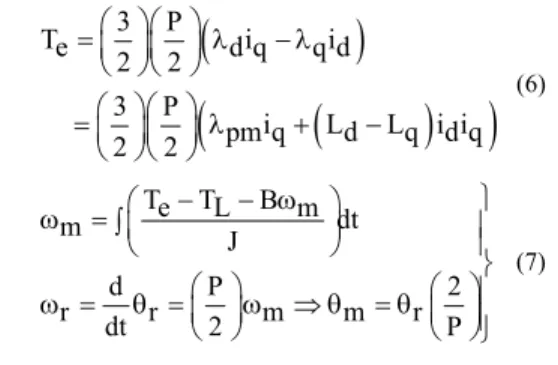
-Fig. 4 The PMSM equivalent circuit in the DQ-axis From the (4)-(5), the developed torque (
Te
) and the angular motor speed (
m
) can be calculated in (6)-(7).Asia Pacific Conference on Robot IoT System Development and Platform 2020 (APRIS2020)
3
P
T
e
d q
i
q d
i
2
2
3
P
i
L
L
i i
pm q
d
q d q
2
2
(6)T
e
T
L
B
m dt
m
J
d
P
2
r
dt
r
2
m
m
r
P
(7)4. Model Validation
The simulation for model validation uses the exact topology model in SimPowerSystem of MATLAB/Simulink called the benchmark model. The parameters of the PMSM in Fig. 1 are given in Table 1. The proposed model implemented by MATLAB/Simulink is illustrated in Fig. 5.
Table. 1 Parameters of the PMSM
Symbol Description Value
RS Stator resistance 0 55 Ω
Ld D-axis inductance 16 61 mH
Lq Q-axis inductance 16 22 mH
pm
Permanent magnet flux 0 121 Vs
J Rotor inertia 7 2460 10 3kg m2
P Pole pair 4
PS Rated power 750 W
NS Rated speed 3000 rpm
Fig. 5 The simulation model used to validate the PMSM model Fig. 6 shows the response comparison of stator current, load torque, and motor speed between the DQ model and the benchmark model.
(a) Stator current at phase A
(b) Changing torque and speed Fig. 6 Model verification
The testing condition for model validation consists of the load torque changing and frequency changing which are detailed as presented in Table 2 and 3, respectively.
Table. 2 The model validation results for load torque changing
Load torque
(N.m)
Model
Measured value
Vabc(V) Iabc(A) Speed (rpm) Torque (N m) 1 DQ 219 97 36 81 750 1 Benchmark 219 97 36 82 750 1 039 3 DQ 219 97 36 80 750 3 Benchmark 219 97 36 80 750 3 039 5 DQ 220 00 36 80 750 5 Benchmark 220 00 36 80 750 5 039
Table. 3 The model validation results for frequency changing
Frequency (Hz) Model Measured value Vabc (V) Iabc (A) Speed (rpm) Torque (N m) 50 DQ 220 00 36 80 750 5 Benchmark 220 00 36 80 750 5 039 45 DQ 199 93 37 17 675 5 Benchmark 199 93 37 17 675 5 035 40 DQ 179 80 37 59 600 5 Benchmark 179 80 37 60 600 5 031 35 DQ 159 77 38 16 525 5 Benchmark 159 77 38 16 525 5 027 30 DQ 139 83 38 92 450 5 Benchmark 139 83 38 92 450 5 023
5. Conclusion
This paper presents how to derive the DQ model of the PMSM by using the DQ modeling method. The results confirm that the mathematical model of the PMSM from DQ modeling method provides a good accuracy compared with the simulation results from the exact topology model. In the future work, the authors will use the proposed model of the PMSM on DQ-axis to design the field oriented control (FOC) for PMSM drives.
Acknowledgments
The authors express their thanks to Prince of Songkla University.
Reference
[1] A.Mishra, J.Makwana, P.Agarwal and S.P. Srivastava, "Mathematical modeling and fuzzy based speed control of permanent magnet synchronous motor drive," 2012 7th IEEE Conference on Industrial Electronics and Applications (ICIEA), Singapore, pp. 2034-2038, 2012. [2] K. Zhao et al., "Robust Model-Free Nonsingular Terminal
Sliding Mode Control for PMSM Demagnetization Fault," in IEEE Access, vol. 7, pp. 15737-15748, 2019.
[3] K. Tatemarsu, D. Hamada, K. Uchida, S. Wakao and T. Onuki, "New approaches with sensorless drives," in IEEE Industry Applications Magazine, vol. 6, no. 4, pp. 44-50, July-Aug. 2000.
Asia Pacific Conference on Robot IoT System Development and Platform 2020 (APRIS2020)