Versatile synthesis and properties of sulfonated
polyphenylene derivatives
A Doctoral Thesis
Presented to
Special Doctoral Program for Green Energy Conversion Science and Technology
Integrated Graduate School of Medicine, Engineering and Agricultural Science
University of Yamanashi
March 2020
1
1.1 General introduction---3
1.2 Proton exchange membrane fuel cells (PEMFCs)---4
1.2.1 Current status and issues of PEMFCs---4
1.2.2 Perfluorosulfonic acid ionomers as proton exchange membrane---6
1.2.3 Current trends and issues of sulfonated aromatic ionomers---7
1.2.4 Chemical degradation mechanism of SPAE ionomers---8
1.2.5 Approach for improvement of the chemical stability---11
1.3 Objective of this PhD research---14
1.4 Reference---15
Chapter 2: Effect of Sulfonated Triphenylphosphine Oxide Groups in Aromatic Block Copolymers as Proton-exchange Membranes 2.1 Introduction---18
2.2 Experimental---19
2.2.1 Materials ---19
2.2.2 Measurements ---20
2.2.3 Synthesis of the hydroxy (OH)-terminated telechelic oligomers 1---21
2.2.4 Synthesis of the hydrophilic oligomer containing the phosphinoxide moiety-24 2.2.5 Synthesis of multiblock copolymers (PP)---30
2.3 Result and discussion ---32
2.3.1 Synthesis of the hydroxy (OH)-terminated telechelic oligomers 1---32
2.3.2 Synthesis of the hydrophilic oligomer containing the phosphinoxide moiety-32 2.3.3 Synthesis of multiblock copolymers (PP)---34
2.3.4 Morphology---35
2.3.5 Proton conductivity and water uptake---37
2.3.6 DMA ---39
2.3.7 Oxidative stability ---41
2.4 Conclusion ---43
2.5 Reference---43
Chapter 3: Versatile Synthesis of Sulfonated Aromatic Copolymers Using NiBr2 3.1 Introduction---45
3.2 Experimental---46
2
3.2.2 Measurements ---47
3.2.3 Synthesis of Protected Monomer (1)---48
3.2.4 Copolymerization Reaction ---50
3.2.5 Deprotection Reaction ---50
3.2.6 Membrane Preparation---51
3.3 Result and discussion ---51
3.4 Conclusion ---60
3.5 Reference---60
Chapter 4: Differences in the Synthetic Method Affected Copolymer Sequence and Membrane Properties of Sulfonated Polymers 4.1 Introduction---62 4.2 Experimental---64 4.2.1 Materials ---64 4.2.2 Measurements ---65 4.2.3 Copolymerization Reaction ---66 4.2.4 Deprotection Reaction ---67 4.2.5 Membrane Preparation---67
4.3 Result and discussion ---68
4.3.1 Synthesis and Characterization ---68
4.3.2 Morphology---75
4.3.3 Water Uptake and Ion Conductivity---80
4.3.4 Mechanical Properties---84
4.4 Conclusion ---88
4.5 Reference---90
Chapter 5: General conclusion and Future proposal 5.1 General conclusions ---91 5.2 Future proposal ---93 List of publications---97 Meeting Abstracts ---98 Awards - ---100 Acknowledgments---101
3
Since the industrial revolution, several countries centered upon the United Kingdom had
achieved economic, industrial and agricultural development. In particular, energy revolution
from the natural energy to fossil fuel such as petroleum and coal significantly improved the
productivity of manufactured product, which made the rich and convenient life.1 However,
economic development with the fossil fuel was a burden to environment due to the emission
of a large amount of greenhouse gases such as CO2, NOx and SOx. In 1896, Arrhenius
reported that concentration of CO2 in the atmosphere impacted on the temperature of the
ground.2 It has been reported so far that the globally averaged combined land and ocean
surface temperature increased by 0.85 oC from 1880 to 2012, and CO
2 concentration in the
atmosphere have also increased by 40% since pre-industrial times.3 Therefore, increase of
CO2 concentration in the atmosphere is considered as matter of major cause for global
warming. To investigate the detail of correlation between the CO2 concentration in
atmosphere and global warming, ministry of the environment, national institute for
environmental studies (NIES) and Japan aerospace exploration agency (JAXA) developed the
greenhouse gases observing satellite (GOSAT) called as "IBUKI" and started the
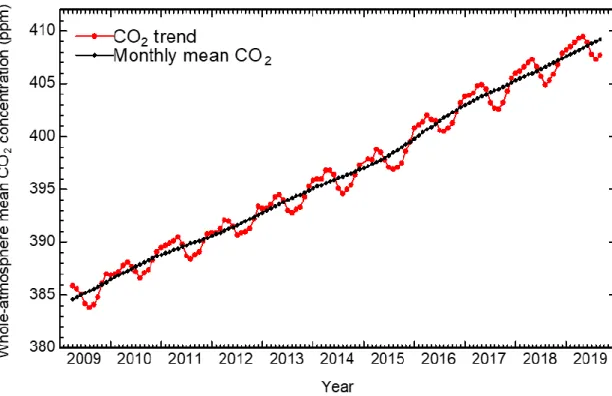
measurement of CO2 concentration in the atmosphere.4 As shown in Figure 1-1, CO2
concentration has been increasing by approximately 2 ppm per year from 2009, despite
improved energy conversion system with low emission of CO2.5 To reduce the CO2
concentration in the atmosphere, the several innovative energy conversion systems without
4
exchange membrane fuel cells using hydrogen as a fuel have attracted much attention to create
the low carbon societies.
Figure 1-1. Trend of whole-atmosphere mean CO2 concentration measured by IBUKI.5
1.2 Proton exchange membrane fuel cells (PEMFCs)
1.2.1 Current status and issues of PEMFCs
Proton exchange membrane fuel cells (PEMFCs) have attracted considerable attention as
alternative energy devices to traditional thermal power generation and internal combustion
engines because PEMFCs operated with pure H2 emit only water as a by-product, i.e.,
zero-carbon energy conversion system.6-9 In 2009, co-generation fuel cell systems (CG-FCs) have
been commercialized in Japan, which provided not only electric power but also hot water at
5
of economy, trade and industry (METI) set a binding target to introduce 5,300,000 units of
CG-FCs and 800,000 units of FCVs until 2030 in Japan.10 As of March of 2019, 276,217 units11
of CG-FCs and 3,056 units12 of FCVs have already been introduced in Japan; however, these
numbers are far from achievement of target due to delaying in the spread by the technical
issues for PEMFCs. Therefore, several technical challenges for PEMFCs such as lifetime,
safety, mass productivity, filling time of fuel and infrastructure e.g., hydrogen production,
storage, transportation and distribution (gas station) have to be solved to achieve the above
target. Among them, cost reduction of PEMFCs is especially big agenda for dissemination of
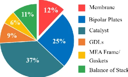
PEMFCs in the market. Figure 1-2 shows the cost analysis of the 2017 projected fuel cell stack
at 100,000 system per year. The proton exchange membrane occupies 12% of the total cost
of PEMFCs and incurs the high cost of the system.13 Therefore, cost effective proton exchange
membranes with improved properties are strongly required.
6
1.2.2 Perfluorosulfonic acid ionomers as proton exchange membrane
Perfuluorosulfonic acid (PFSA) ionomers such as Nafion is generally used as proton
exchange membrane in the PEMFCs because PFSA ionomers show 0.1~0.01 S cm-1 of proton
conductivity at 80 oC due to high acid dissociation constant of the perfluorosulfonic acid
groups (pKa: -5.5 to -6). Generally, the strong electron-withdrawing nature of fluorine atoms leads to stabilization of –CF2-SO3- as the conjugate base, thus protons of sulfonic acid groups
can easily dissociate in the presence of water and become a good source of the proton.14
Furthermore, the hydrophilic side-chain with super acidity promotes the formation of ionic
clusters and well-connected ionic path way within the hydrophobic matrix, resulting in the
improvement of the proton conductivity. Currently, PFSA ionomer reinforced with PTFE
called as Nafion XL has been developed and exhibited approximately two times higher storage
modulus (E’) than that of commercial Nafion 212.15 Y. Oshiba et al. also reported that the
pore-filled membrane consisting of prepared PFSA ionomer and ultra-high molecular weight
polyethylene (UHMWPE) showed much higher tensile strength value (70.0 MPa) than that
of commercial Nafion 211 (29.4 MPa).16 Gore and associates also developed the reinforced
PFSA ionomer with the expanded polytetrafluoroethylene (ePTFE) called as GORE-SELECT
membrane which has been made as thin as approximately 5 µm, resulting in minimizing ohmic
losses of fuel cell.14,17
However, there still remain problems associated with PFSA membranes. PFSA membranes
suffer from some disadvantages such as low environmental compatibility, high production cost,
and high gas permeability. As mentioned above, in order for wider spread commercialization
7
cost, high versatility of molecular structure and high gas barrier properties.
1.2.3 Current trends and issues of sulfonated aromatic ionomers
To replace state-of-the-art PFSA ionomers, sulfonated aromatic ionomers have been
researched and developed all over the world. As representatives, poly(arylene ether)s
(SPAEs),18 poly(arylene sulfide)s (SPASs)19, polyimides (SPIs)20, and polybenzimidazoles
(PBIs)21 have been studied and some were claimed to show the superior mechanical and
thermal stability compared with PFSA ionomers because of their rigid polymer backbone
structures. In particular, SPAE ionomers which could be synthesized from inexpensive raw
materials via simple synthetic route (e.g., nucleophilic aromatic substitution reaction) have
attracted much attention to replace PFSA ionomers. Kim et al. reported that pendant
dual-sulfonated poly(arylene ether ketone)s (SPEEKs) multiblock copolymers with 1.92 meq g-1 of
ion exchange capacity (IEC) estimated by inverse titration method exhibited the excellent
proton conductivity (80 mS cm-1) at 80 oC and 80% RH due to the well-developed
phase-separation with well-connected hydrophilic ionic channel (Figure 1-3).22
8
McGrath et al. clarified that the longer block length of hydrophilic and hydrophobic
repeating units in the polymer main chain induced more distinct nanophase separation and
better connectivity among the ionic domains i.e., the primary structure (or sequence of the
components) of the polymer chain affected the membrane morphology and proton
conductivity (Figure 1-4).23 However, most sulfonated aromatic ionomers showed the low
chemical stability to radial species derived from hydrogen peroxide, accordingly indicating the
lower cell performance and lifetime for FC stacks.
1.2.4 Chemical degradation mechanism of SPAE ionomers
Radical species such as hydroxyl and hydroperoxyl radicals are produced as by-product in
the operating PEMFCs conditions at both electrode sides. In the anode side, oxygen
permeated through the membrane from the cathode to the anode directly reacts with H2,
which generates the hydrogen peroxide followed by incomplete reduction at the surface of the
anode catalyst. On the other hand, oxygen reduction at the cathode proceeds not only
four-electron process but also two-four-electron process, resulting in the generation of hydrogen
peroxide. Radical species are known to form by homolytic and heterolytic dissociation of
hydrogen peroxide, in particular, in the presence of Fe ions. 24
In general, radical species which are produced as by-product in FC operating conditions
cause the chemical degradation of the proton exchange membrane, which lead to the increase Figure 1-4. Chemical structure of BisSF-BPSH multiblock copolymer.23
9
reported the chemical degradation mechanism of SPAE ionomers as shown in scheme 1-1.
Hydroxyl radical attacks to the positions of the aromatic ring next to the ether linkage because
of high electron density provided from the unshared electron pair of oxygen. After the
addition of hydroxyl radical, the scission of the ether bonds might take place by ipso-attack of hydroxyl radical to the -OR groups, due to the activating effect of hydroxyl substituents in the
ortho position to -OR (Scheme 1-1 (a)).28 Another possibility is the direct ipso-attack of
hydroxyl radicals to the -OR groups of typical poly(arylene ether)s as shown in Scheme 1-1
10
Scheme 1-1. Chemical degradation process of SPAE ionomers.28
(a)
11
vulnerable to radical species because of high electron density provided from the unshared
electron pair of oxygen. Therefore, many researchers have studied to improve the chemical
stability of sulfonated aromatic ionomers, and there seemed two major approaches as follows
to overcome these issues
1) Addition of the radical scavengers in the membranes
Cerium ion is a typical additive to quench the radical species. Kim et al. suggested the radical
quenching mechanism through reversible oxidation and reduction of Ce3+ and Ce4+ as
follows.29 Endoh et al. also reported that the use of Ce3+ as radical quencher enhanced the
chemical stability of PFSA ionomer by a factor of 100 to 1,000. Moreover, fuel cell with Ce3+
composite PFSA ionomer could operate for 6,000 hours at 120 oC and 50% relative humidity
condition.30 Ce3+ + ·OH + H+ → Ce4+ + H 2O (1) Ce3+ + ·OOH + H+ → Ce4+ + H 2O2 (2) Ce4+ + H 2O2 → Ce3+ + ·OOH + H+ (3) Ce4+ + ·OOH → Ce3+ + O 2+ H+ (4)
Kim et al. reported that the weight loss of cerium composite SPEEKs after Fenton's test at
room temperature is only 27%, where pristine sulfonated aromatic ionomer showed 100% of
weight loss.29
However, the cerium ion composite membrane system has two disadvantages. First, cerium
12
of the proton, decreasing the proton conductivity and the cell performance. Second, cerium
ions are mobile in the operating PEMFCs conditions and thus easy to leach out from the
membrane by diffusion process.
2) Elimination of ether linkages from the polymer backbone
As discussed in the section 1.2.4, chemical degradation by radical species occurs at the or
near the polar linkage such as ether. Holdcroft et al. reported that a sulfophenylated
terphenylene copolymer membrane without ether linkage having IEC of 3.70 meq g-1
displayed no practical weight loss and chemical degradation in the oxidative stability test (at
80 ºC in Fenton’s reagent (Figure 1-5).31
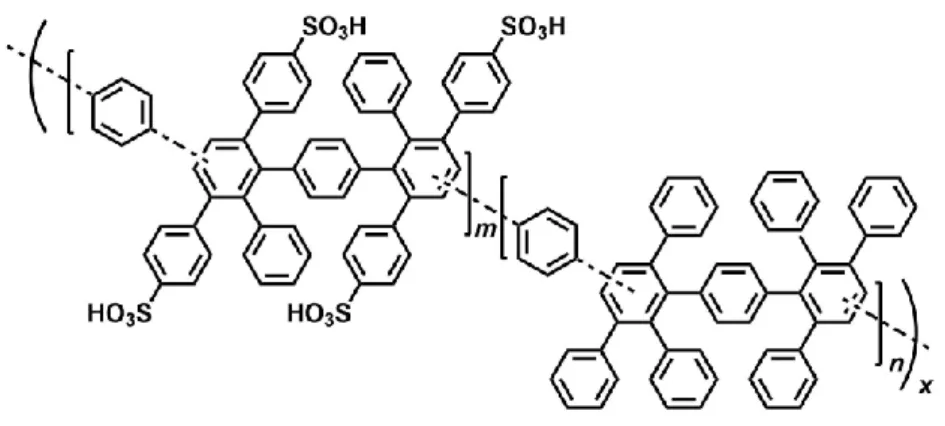
Our laboratory has also developed a series of sulfonated aromatic ionomers without the ether
linkage in polymer main chain composed of sulfo-1,4-phenylene groups as the hydrophilic
component, and hexafluoroisopropylidene (SBAF)32, or quinquephenylene (SPP-QP)33
groups as the hydrophobic component. As shown in Table 1, these membranes had
significantly high chemical stability in the oxidative stability test.32,33 However, these
13
copolymerization reactions to obtain high molecular weight polymers, which undermines the
advantages of potentially inexpensive hydrocarbon-based materials.
Figure 1-6. Chemical structure of SPP-QP and SBAF copolymers.32,33
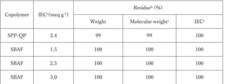
Table 1-1. Oxidative stability of SPP-QP and SBAF membranes.32,33
a: Calculated from back titration b:After Fenton’s test at 80 oC for 1 h.
c: Determined by GPC analyses (calibrated with polystyrene standards). Copolymer IECa(meq g-1)
Residueb (%)
Weight Molecular weightc IECa
SPP-QP 2.4 99 99 100
SBAF 1.5 100 100 100
SBAF 2.5 100 100 100
14 1.3 Objective of this PhD research
For all of these reasons, sulfonated aromatic ionomer membranes are greatly demanded as
alternatives to the PFSA ionomers, however, chemically stable sulfonated aromatic ionomer
with cost-effectiveness has not been developed yet. Therefore, the objective of this PhD
research is to develop a highly proton conductive sulfonated aromatic ionomer with high
chemical stability in consideration of mass production and dissemination. To accomplish this
objective, two approaches, i.e., effect of radical quencher and elimination of ether linkage,
have been tried and investigated as explained in chapter 1.2.5. in this doctoral thesis.
In chapter 2, the phosphine oxide moiety serving as a radical quencher is focused to improve
the oxidative stability and by direct introduction into polymer main chain of SPAE with low
cost and simply synthetic procedure. The effect of triphenyl phosphine oxide moieties in
hydrophilic components on oxidative stability is explained.
In chapter 3, new versatile synthesis method for sulfonated aromatic copolymers using
commercially available and low-cost NiBr2 is investigated. Moreover, effect of difference in
the synthetic route between conventional method with Ni(0) complex and new method with
NiBr2 on the membrane properties such as proton conductivity, mechanical property and
15
Twentieth-Century World, (2001)
2 S. Arrhenius, Lond. Edinb. Dublin Phil. Mag. J. Sci. (5th ser..). 1896, 41, 237.
3 IPCC “Climate Change 2013 - The Physical Science Basis”
https://www.ipcc.ch/site/assets/uploads/2018/02/WG1AR5_SPM_FINAL.pdf
4 Satellite Observation Center “Global Greenhouse Gas Observation by Satellite GOSAT Project”
http://www.gosat.nies.go.jp/eng/GOSAT_pamphlet_en.pdf
5 National Institute for Environmental Studies “Whole-atmosphere monthly mean CO2 concentration based on GOSAT observations -Recent data-“
http://www.gosat.nies.go.jp/en/recentglobalghg.html
6 E4tech Strategy Energy Sustainability “The Fuel Cell Industry Review 2018”
https://www.californiahydrogen.org/wp-content/uploads/2019/01/TheFuelCellIndustryReview2018.pdf
7 F. Baldi, L. Wang, M. Pérez-Fortes, F. Marechal, Frontiers in Energy Research 2018, 6, 139.
8 A. Arshad, H.M. Ali, A. Habib, M.A. Bashir, M. Jabbal, Y. Yan, Therm. Sci. Eng. Prog.
2019, 9, 308.
9 I. Staffell, D. Scamman, A.V. Abad, P. Balcombe, P.E. Dodds, P. Ekins, N. Shah, K.R. W ard, Energy Environ. Sci. 2019, 12,463.
~Industry-academia-16
government action plan to realize Hydrogen Society~”
https://www.meti.go.jp/press/2018/03/20190312001/20190312001-1.pdf
11 Enefarm Partners
https://www.gas.or.jp/user/comfortable-life/enefarm-partners/common/data/20190423_web.pdf
12 METI “Progress of The Strategic Road Map for Hydrogen and Fuel Cells”
https://www.meti.go.jp/shingikai/energy_environment/suiso_nenryo/roadmap_hyoka_
wg/pdf/001_04_00.pdf
13 DOE Hydrogen and Fuel Cells Program Record “Fuel Cell System Cost -2017-“ https://www.hydrogen.energy.gov/pdfs/17007_fuel_cell_system_cost_2017.pdf
14 A. Kusoglu, A. Z. Weber, Chem. Rev. 2017, 117, 987.
15 S. Shi, A.Z. Weber, A. Kusoglu, J. Membr. Sci. 2016, 516, 123.
16 Y. Oshiba, J. Tomatsu, T. Yamaguchi, J. Power Sources 2018, 394, 67. 17 W. Liu, T. Suzuki, H. Mao, T. Schmiedel, ECS Trans. 2012, 50, 51.. 18 D.W. Shin, M.D. Guiver, Y.M. Lee, Chem. Rev. 2017, 117, 4759.
19 Z. Wang, H.Z. Ni, C.J. Zhao, M.Y. Zhang, H. Na, J. Appl. Polym. Sci. 2009, 112, 858. 20 K.H. Lee, S.Y. Lee, D.W. Shin, C. Wang, S.-H. Ahn, K.-J. Lee, M.D. Guiver, Y.M. Lee,
Polymer 2014, 55, 1317.
21 X. Qiu, M. Ueda, H. Hu, Y. Sui, X. Zhang, L. Wang, ACS Appl. Mater.Interfaces 2017, 9, 33049.
22 K. Kang, D. Kim, J. Membr. Sci. 2019, 578, 103.
17
25 J.R. Yu, B.L. Yi, D.M. Xing, F.Q. Liu, Z.G. Shao, Y.Z. Fu, H.M. Zhang, Phys. Chem. Chem. Phys. 2003, 5, 611.
26 A.B. LaConti, H. Liu, C. Mittelsteadt, R.C. McDonald, ECS Trans. 2006, 1, 199. 27 D.A. Schiraldi, D. Savant, C. Zhou, ECS Trans. 2010, 33, 883.
28 L. Zhang, S. Mukerjee, J. Electrochem. Soc. 2006, 153, A1062. 29 S. Yang, D. Kim, J. Power Sources 2018, 393, 11.
30 E. Endoh, N. Onoda, Y. Kaneko, Y. Hasegawa, S. Uchiike, Y. Takagi, T. Take, ECS Electrochem. Lett. 2013, 2, F73.
31 T. J. G. Skalski, M. Adamski, B. Britton, E. M. Schibli, T. J. Peckham, T. Weissbach, T. Moshisuki, S. Lyonnard, B. J. Frisken, S. Holdcroft, ChemSusChem 2018, 11, 4033. 32 J. Ahn, R. Shimizu, K. Miyatake, J. Mater. Chem. A 2018, 6, 24625.
33 J. Miyake, R. Taki, T. Mochizuki, R. Shimizu, R. Akiyama, M. Uchida, K. Miyatake, Sci. Adv. 2017, 3, eaao0476.
18
Chapter 2: Effect of Sulfonated Triphenylphosphine
Oxide Groups in Aromatic Block Copolymers
as Proton-exchange Membranes
2.1 Introduction
Proton-exchange membranes (PEMs) are one of the key components in proton-exchange
membrane fuel cells.1 Currently, perfluorinated (PFSA) ionomer membranes are
state-of-the-art because they show very high proton conductivity and good mechanical and chemical
stability under fuel cell operating conditions. However, there has been great demand for
fluorinefree PEMs in order to lower the production cost and the environmental impact.
Sulfonated poly(arylene ether)s (SPAEs) are one of the most studied alternative PEMs due
to the easy synthetic process, molecular design versatility, and good film forming capability.
2-10 Among them, the multiblock copolymers composed of sulfonated and un-sulfonated blocks
showed improved proton conductivity due to a well-developed hydrophilichydrophobic
phase-separated morphology with interconnected ionic channels.11-15 Most SPAE based PEMs,
however, suffer from insufficient mechanical stability under wet/dry cycle conditions.
Furthermore, the poor oxidative stability of SPAE-based PEMs is also a critical issue.
To address these issues, our laboratory has demonstrated that the introduction of sulfonated
triphenylphosphine oxide moieties contributes to the improvement of the oxidative stability
of SPAE-based PEMs (PK,16 Figure 2-1). Although the position and content of the sulfonated
triphenylphosphine oxide moieties must affect the oxidative and mechanical stability of the
19
membranes are compared with those of the PK membrane sharing similar hydrophobic blocks
but with a different density of the sulfonated triphenylphosphine oxide moieties.
Figure 2-1. Chemical structure of the PP copolymer and the reference copolymer PK.
2.2 Experimental
2.2.1 Materials
N,N-Dimethylacetamide (DMAc), dimethyl sulfoxide (DMSO), N-methyl-2-pyrrolidinone (NMP), toluene (dehydrated), 30 wt% oleum, sulfuric acid (96%), hydrochloric acid
(35-37%), potassium carbonate (K2CO3), calcium carbonate (CaCO3), and sodium chloride
(NaCl) were purchased from Kanto Chemical Co. and used as received.
Bis(4-fluorophenyl)sulfone (FPS) and N-bromosuccinimide (NBS) were purchased from TCI Inc.
and used as received. Methanol was purchased from Wako and used as received. DMSO-d6
(0.03% tetramethylsilane (TMS) and 99.9 atom% D) and 1,1,2,2-tetrachloroethane-d2
(TCE-d2, 99 atom% D) were purchased from Acros Organics and used as received.
Spectra/Por 6 dialysis tubing (1,000 Da MWCO) was purchased from Spectrum Laboratories,
20
from Aldrich and used as received. m-Terphenyl (MTP) monomer, 1,3-bis(4-hydroxyphenyl)benzene, was provided by Honshu Chemical Industry Co., Ltd. and used as
received. Bis(4-hydroxyphenyl)phenylphosphine oxide (BHPPO)17 and
bis(3-bromo-4-fluorophenyl)sulfone (BrFPS)18 were synthesized according to the literature.
2.2.2 Measurements
1H (500 MHz), 19F (471 MHz), and 31P (202 MHz) NMR spectra were obtained on a JEOL
JNM-ECA 500 using DMSO-d6 or TCE-d2. Apparent molecular weight was estimated from
gel permeation chromatography (GPC) system with a Jasco 805 UV detector. DMF
containing 0.01 M LiBr was used as eluent. A Shodex K-805L column was used for sulfonated
compounds and a Shodex SB-803HQ column was used for un-sulfonated compounds,
respectively. Molecular weight was calibrated with standard polystyrene samples. Ion
exchange capacity (IEC) values of membranes were calculated from back-titration method.
Water uptake and proton conductivity were measured at 80 oC with a solid electrolyte analyzer
system (MSBAD-V-FC, Bel Japan Co.) equipped with a temperature and humidity
controllable chamber. Weight of the membranes was measured by magnetic suspension
balance at given humidity, and then water uptake ((weight of hydrated membrane) – (weight
of dry membrane) / weight of dry membrane×100) was obtained. Vacuum drying for 3 h at
80 oC gave the weight of dry membranes and exposure to a targeted humidity for at least 2 h
gave the weight of hydrated membranes. Proton conductivity was measured using four-probe
conductivity cell attached with impedance spectroscopy (Solartron 1255B and 1287)
21
distance between the two inner Au wires and the conducting area, respectively. Dynamic
mechanical analysis (DMA) was carried out with an ITK DVA-225 dynamic viscoelastic
analyzer. Humidity dependence of storage modulus (E'), loss modulus (E''), and tanδ at 80
oC was investigated for membranes (5 mm × 30 mm) at a humidification rate of 1% relative
humidity (RH) per minute. Oxidative stability of membranes was checked by immersing
membranes in Fenton’s reagent (3% H2O2, 2 ppm FeSO4) at 80 oC for 1 h. Loss of weight and
molecular weight were checked for the samples after the stability test. For TEM observations,
the membranes were stained with lead ions by ion exchange of the sulfonic acid groups in 0.5
M lead (II) acetate aqueous solution, rinsed with deionized water, and dried. The stained
membranes were embedded in epoxy resin, sectioned to 50 nm thickness with Leica
microtome Ultracut UCT, and placed on copper grids. Images were taken on a Hitachi
H-9500 TEM with an accelerating voltage of 200 kV.
2.2.3 Synthesis of the hydroxy (OH)-terminated telechelic oligomers 1
A typical procedure is as follows (X=3). A 100 mL three-necked round bottom flask
equipped with a magnetic stirring bar, a condenser, a Dean-Stark trap, and a nitrogen
inlet/outlet, was charged with MTP monomer (3.81 mmol), FPS (2.86 mmol), K2CO3 (9.52
mmol), DMAc (6.7 mL), and toluene (0.5 mL). The mixture was heated at 140 oC for 3 h.
After the reaction, the reaction mixture was poured into a 1 M hydrochloric acid to precipitate
22
times. Drying in a vacuum oven gave oligomer in 89% yield (X values; targeted = 3.0, 1H
NMR = 5.1, GPC = 7.5).
X=6 was prepared under the condition similar to that for X = 3. MTP monomer (5.72 mmol),
FPS (4.90 mmol), K2CO3 (14.3 mmol), DMAc (10 mL), and toluene (0.5 mL) were used.
93% yield (X values; targeted = 6.0, 1H NMR = 10, GPC = 12).
Scheme 2-1. Synthesis of the hydroxy (OH)-terminated telechelic oligomers 1
Oligomer
23 Figure 2-2. (a) 1H, (b) 19F NMR spectra (TCE-d
2, 80 oC), and (c) GPC profile of 1 oligomer.
7.0
7.5
8.0
δ/ ppm
4
5
6
8
10
7,9,11,12
X=3
7.0
7.5
8.0
δ/ ppm
5
10
4
6
7,9,11,12
8
-120
-110
-100
-90
-80
δ/ ppm
X=3
-120
-110
-100
-90
-80
δ/ ppm
X=6
(b)10
15
20
25
retention time (min)
UV
a
bs
o
rb
an
c
e
a
t
2
7
0
n
m
(
a
.u
.)
Mn:3.86 kDa
Mw:7.03 kDa
Mw/Mn 1.82
X=3
10
15
20
25
retention time (min)
UV
a
b
s
o
rb
a
n
c
e
a
t
2
7
0
n
m
(
a
.u
.)
Mn:5.82 kDa
Mw:12.7 kDa
Mw/Mn 2.18
X=6
(c)24
2.2.4 Synthesis of the hydrophilic oligomer containing the phosphine oxide moiety
[BHPPO-terminated oligomer]
A 100 mL three-necked round bottom flask equipped with a magnetic stirring bar, a
condenser, a Dean-Stark trap, and a nitrogen inlet/outlet, was charged with BHPPO (4.83
mmol), FPPO (2.42 mmol), K2CO3 (12.1 mmol), DMAc (8 mL), and toluene (1.6 mL). After
the reaction was conducted at 160 oC for 20 h, the reaction mixture was poured into a 1 M
hydrochloric acid to precipitate a solid. The crude product was washed with hot deionized
water several times. Drying in a vacuum oven gave oligomer in 87% yield (Y values; targeted
= 1.0, 1H NMR = 1.6).
Scheme 2-2. Synthesis of the hydrophilic oligomer containing the phosphine oxide moiety
25
Figure 2-3. (a) 1H, (b) 19F, (c) 31P NMR spectra (DMSO-d
6, 80 °C), and (d) GPC profile of BHPPO-terminated oligomer.
6.5
7.0
7.5
8.0
δ/ ppm
1
6
7
2,3,4,5
-120
-115
-110
-105
-100
δ/ ppm
20
25
30
δ/ ppm
i
ii
10
15
20
25
retention time (min)
UV
a
b
s
o
rb
a
n
c
e
a
t
2
7
0
n
m
(
a
.u
.)
(c) (d)26 [Hydrophilic oligomer precursor]
A 100 mL three-necked round bottom flask equipped with a magnetic stirring bar, a
condenser, a Dean-Stark trap, and a nitrogen inlet/outlet, was charged with
BHPPO-terminated oligomer (1.58 mmol), BrFPS (4.74 mmol), K2CO3 (4.74 mmol), DMAc (25 mL),
and toluene (5 mL). After the reaction was conducted at 160 oC for 3 h, the reaction mixture
was poured into a 1 M hydrochloric acid to precipitate a solid. The resulting solid was washed
with hot deionized water several times. Drying in a vacuum oven gave oligomer.
27
Figure 2-4. (a) 1H, (b) 19F, (c) 31P NMR spectra (DMSO-d
6, 80 oC), and (d) GPC profile
of hydrophilic oligomer precursor.
6.5
7.0
7.5
8.0
8.5
δ/ ppm
6,BrFPS
BrFPS
8
1
4
2,3,5,7,BrFPS
-105
-104
-103
δ/ ppm
BrFPS
Oligomer
24
25
26
δ/ ppm
i
ii
10
15
20
25
retention time (min)
UV
a
bs
o
rb
an
c
e
a
t
2
7
0
n
m
(
a
.u
.)
Mn:1.44 kDa
Mw:2.61 kDa
Mw/Mn:1.81
(d) (c)28 [Hydrophilic oligomer (2)]
A 100 mL round bottom flask equipped with a magnetic stirring bar was charged with
hydrophilic oligomer precursor (1.50 mmol) and 30 wt% oleum (18 mL). The amount of 30
wt% oleum was adjusted to be 5 excess equimolar of SO3 to the phenyl rings in the oligomer.
After the sulfonation reaction at r.t. for 48 h, the reaction mixture was poured into H2O,
basified with NaOH aqueous solution, dialyzed, and dried to give the targeted oligomer 2 in
73% yield. (Y value; 1H NMR = 1.9).
29
Figure 2-5. (a) 1H, (b) 19F, and (c) 31P NMR spectra (DMSO-d
6, 80 oC) of oligomer 2.
7.0
7.5
8.0
8.5
δ/ ppm
13
14
1
7,9
6,12
3,8,11,16
2,4,5,10,15
-100
-99
-98
δ/ ppm
24
25
26
δ/ ppm
i
ii
(c)30
2.2.5 Synthesis of multiblock copolymers (PP)
A typical procedure is as follows (X5Y2). A 100 mL three-necked round bottom flask
equipped with a magnetic stirring bar, a condenser, a Dean-Stark trap, and a nitrogen
inlet/outlet, was charged with oligomer 1 (0.142 mmol), oligomer 2 (0.142 mmol), K2CO3
(0.568 mmol), CaCO3 (1.42 mmol), DMSO (5 mL), and toluene (1 mL). After the mixture
was conducted at 140 oC for 21 h, the reaction mixture was poured into a 1 M hydrochloric
acid. The crude mixture was dialyzed and dried to give the targeted polymer PP in 67% yield.
X10Y2 was synthesized under the conditions similar to those for X5Y2. Oligomer 1 (0.142
mmol), oligomer 2 (0.142 mmol), K2CO3 (0.568 mmol), CaCO3 (1.42 mmol), DMSO (5 mL),
and toluene (1 mL). 71% yield.
31 Figure 2-6. (a) 1H NMR spectrum (DMSO-d
6 80 oC) and (b) GPC profiles
6.5
7.0
7.5
8.0
8.5
δ/ ppm
a,h
m,g
1
4
5,f,j
6,7,c,d,e,l
2,3
b
j
X5Y2
6.5
7.0
7.5
8.0
8.5
δ/ ppm
a,h
m,g
1
4
5,f,j
6,7,c,d,e,l
2,3
b
j
6
8
10
12
retention time (min)
UV
a
b
s
o
rb
a
n
c
e
a
t
2
7
0
n
m
(
a
.u
.)
hydrophobic
hydrophilic
polymer(X5Y2)
Mn:39.2 kDa
Mw:183 kDa
Mw/Mn:4.67
X5Y2
6
8
10
12
retention time (min)
UV
a
b
s
o
rb
a
n
c
e
a
t
2
7
0
n
m
(
a
.u
.)
X10Y2
hydrophobic
hydrophilic
polymer(X10Y2)
Mn:40.2 kDa
Mw:306 kDa
Mw/Mn:7.62
32 2.3 Result and discussion
2.3.1 Synthesis of the hydroxy (OH)-terminated telechelic oligomers 1
Scheme 1a represents the synthetic route for the title block copolymers PP. First of all, the
hydrophobic oligomers 1 were prepared according to the literature (Scheme 2-1).15 The
nucleophilic substitution polymerization of a slight excess of 1,3-bis(4-
hydroxyphenyl)benzene (MTP) with bis(4-fluorophenyl)sulfone (FPS) under basic
conditions provided the hydroxy (OH)-terminated telechelic oligomers 1. The number of
repeat units (X = 3 and 6) was controlled by the feed comonomer ratio. The chemical
structure of oligomers 1 was confirmed by 1H and 19F NMR spectra (Figure 2-2), in which all
signals were well-assigned to the supposed chemical structure. The X values obtained by 1H
NMR spectra (ca. 5 and 10) were slightly higher than the targeted values (X = 3 and 6). The
X values estimated from GPC analyses (ca. 8 and 12) were even higher than those above,
probably because the oligomers 1 comprise a rigid molecular structure and are eluted faster
in our GPC system than the standard polystyrene samples. Therefore, the values (X = 5, 10)
determined by 1H NMR spectra were used as the number of repeat units of the oligomers 1
for the following block copolymerization reaction.
2.3.2 Synthesis of the hydrophilic oligomer containing the phosphinoxide moiety
The hydrophilic oligomer 2 was synthesized in three steps, i.e., nucleophilic substitution
polymerization reaction, endcapping with bis(3-bromo-4-fluorophenyl)sulfone (BrFPS),
followed by sulfonation reaction. First, the OH-terminated telechelic oligomer was prepared
bis(4-33
which all signals were well-assigned. GPC data, however, showed much lower values than
expected. This result is consistent with our previous work, in which the oligomers containing
triphenylphosphine oxide moieties had some interaction with our GPC columns, resulting in
underestimation of the molecular weights.16 Since the oligomer in this study carries more
triphenylphosphine oxide groups than the previous oligomer, the interaction might become
more prominent. On the contrary, the Y value (2) obtained from the 1H NMR spectrum was
reasonable (targeted Y = 1).
Then, the endcapping reaction with BrFPS was carried out in a similar manner as described
for the oligomer (Scheme 2-3). Endcapping with the brominated compound was carried out
to increase the reactivity in the following block copolymerization reaction.19 The 1H, 19F, and
31P NMR spectra suggested the formation of the targeted BrFPS-terminated oligomer (Figure
2-4). Although the monomeric BrFPS was contaminated (two 19F NMR signals), this could
be easily removed in the next step.
The sulfonation reaction of the BrFPS-terminated oligomer was conducted to synthesize
hydrophilic oligomer 2 (Scheme 2-4). The 1H, 19F, and 31P NMR spectra suggested the
formation of targeted oligomer 2 (Figure 2-5). In the 31P NMR spectrum, two signals were
observed, which can be assigned as phosphorous atoms in the repeat unit and at the chain
terminals, respectively. In the 19F NMR spectrum, the hydrophilic oligomer 2 showed a single
peak at -99.3 ppm, which was significantly shifted to the lower magnetic field compared to
34
oxide (FPPO) terminals (-107.2 ppm).16 The result suggests that 2 would be more reactive
than the non-endcapped hydrophilic oligomer.20 Furthermore, the single 19F NMR peak
supported the successful removal of the BrFPS contaminant.
2.3.3 Synthesis of multiblock copolymers (PP)
Block copolymerization of 1 and 2 was carried out under conditions similar to that for the
oligomerization reaction (Scheme 2-5). The obtained copolymers 3 possessed high molecular
weights (apparent Mw = 183-306 kDa, Table 1) and were soluble in polar organic solvents.
Casting from NMP solutions provided thin bendable membranes (ca. 30 µm thick). The 1H
NMR spectra of the copolymers confirmed the hydrophilic and hydrophobic components
without detectable terminal groups. The experimental ion exchange capacity (IEC) values
obtained by 1H NMR spectra (Figure 2-6) were comparable to or slightly lower than those
calculated from the feed ratios (Table 1). On the other hand, IEC values obtained by titration
were much lower than these IEC values, suggesting that part of the sulfonic acid groups
embedded in the rather hydrophobic environment did not function as ion exchangeable
groups. Similar behavior was previously observed for the other series of sulfonated block
35
a: Determined by GPC analyses (calibrated with polystyrene standards).
b: After Fenton’s test at 80 oC for 1 h. c: See ref 16.
2.3.4 Morphology
Figure 2-7 shows a TEM image of the PP-X5Y2 membrane stained with lead ions. While the
effect of counter cations might not be negligible, TEM images often provide useful
information on the morphology of ionomer membranes. The PP membrane showed
phase-separated morphology with hydrophilic (black domain) and hydrophobic (white domain)
components. The hydrophilic domain of the PP membrane was narrow with a string-like
structure, which was similar to that of the reference copolymer PK, probably because both
copolymers contained similar, rigid, and linear hydrophilic blocks. The difference lies in their
size, i.e., the width of the hydrophilic parts of the PP membrane was ca. 3 nm, which was
slightly smaller than that of the PK (ca. 5 nm) membrane. The shorter hydrophilic chain
length of PP (Y = 2) compared to PK (Y = 4) must be responsible. The connectivity of the
hydrophilic domains in the PP membrane was somewhat lower than that in the PK membrane. PEMs Composition
Molecular
weighta (kDa)
IEC (meq g-1) Residueb (%)
Mn Mw Target NMR Titration Weight Mwa
PP X5Y2 39 183 2.36 1.90 1.15 80 75
PP X10Y2 40 306 1.71 1.63 0.92 88 74
36
37
as a function of relative humidity (RH). For comparison, data for Nafion NRE 212 and PK
(sharing similar hydrophobic blocks but with a different density of the sulfonated
triphenylphosphine oxide moieties) membranes are also included in Figure 2-8. The water
uptake and proton conductivity of these membranes were dependent on RH, i.e., a higher RH
caused higher water uptake and proton conductivity. The PP membrane with the higher IEC
value (X5Y2, 1.15 meq g-1) showed much higher proton conductivity than that the reference
PK (0.92 meq g-1) membrane due to the former’s higher IEC value. Comparison of PP-X10Y2
(0.92 meq g-1) with PK (0.92 meq g-1) revealed that these two membranes showed comparable
proton conductivity at a wide range of humidities (the PP membrane showed only slightly
lower proton conductivity than PK at 20% RH). Although the PP and PK membranes showed
much lower proton conductivity than the Nafion NRE 212 membrane at low RH, all
membranes showed comparable proton conductivity at high RH, probably due to the higher
38
Figure 2-8. Water uptake and proton conductivity of the membranes (IEC values obtained by
titration in parentheses) at 80 oC as a function of RH.
0
20
40
60
80
100
10
-410
-310
-210
-1Relative humidity (%)
Pr
o
to
n
con
d
u
c
ti
vi
ty
(S
cm
-1)
0
10
20
30
W
a
te
r
u
p
ta
ke
(%)
PP(X5Y2) (1.15 meq g
-1)
PP(X10Y2) (0.92 meq g
-1)
PK(X30Y4) (0.92 meq g
-1)
NRE212 (0.91 meq g
-1)
39
analyses (DMA) under the same conditions as that for water uptake and proton conductivity
measurements (at 80 oC as a function of RH) (Figure 2-9). All membranes showed similar
humidity dependence on storage moduli (E’), loss moduli (E’’), and tanδ, i.e., distinct peaks
at ca. 50-60% RH in the E’’ and tanδ curves were observed. These peaks could be ascribed
to the glass transition of the copolymers, in which the absorbed water acts as a plasticizer.22
The similar behavior indicated that the structural difference (or the content of
triphenylphosphine oxide groups) within this study (PP and PK) did not affect the
40
Figure 2-9. DMA analyses of membranes; (a) E’ (storage moduli), (b) E’’ (loss moduli), and
(c) tanδ at 80 oC as a function of RH.
0
20
40
60
80
10
-210
-1ta
n
Relative humidity (%)
(a)
(b)
(c)
10
810
910
10E'
(Pa
)
PP (X10Y2) (0.92 meq g
-1)
PK (X30Y4) (0.92 meq g
-1)
10
610
710
810
9E'
' (Pa
)
41
for 1 h, and is summarized in Table 1. Under such harsh conditions, most SPAE-based
membranes degrade significantly. In our previous work, membranes without phosphine oxide
groups degraded severely (residual weight and Mw are 57% and 56%, respectively) despite
the similar titration IEC (1.06 meq g-1) and water uptake (18.2%) values.21 In contrast, two
PP membranes exhibited good oxidative stability, retaining more than 80% of the weight and
74% of the weight-averaged molecular weight. The oxidative stability of the PK membrane
with the smaller content of triphenylphosphine oxide groups was even better. This result
indicated that not only the density of the sulfonated triphenylphosphine oxide moieties but
also other factors such as water affinity might affect the oxidative stability of the membranes.
Although the PP membranes have highly dense sulfonated triphenylphosphine oxide moieties,
those of the water uptake were also high. The higher water uptake of the PP membranes might
provide more chances of attack by water-soluble radical species, resulting in degradation of
the PP membranes. Since the post-test-analysis of the PP membranes revealed that
degradation occurred mainly at the hydrophilic parts (Figure 2-10), optimization of the
molecular design in the hydrophilic parts (e.g., the position and density of the sulfonated
42 Figure 2-10. 1H NMR spectra (DMSO-d
6, 80 oC) of the PP-X5Y2 sand PP-X10Y2 membranes
43
dense sulfonated triphenylphosphine oxide moieties in the hydrophilic blocks. The obtained
copolymer PP possessed high molecular weight and good solubility in polar organic solvents.
Solution casting produced self-standing and bendable PP membranes. It is indicated that the
introduction of sulfonated triphenylphosphine oxide moieties is effective in improving the
oxidative stability of the membranes. However, detailed comparison with the PK membrane
sharing similar hydrophobic blocks but a smaller content of sulfonated triphenylphosphine
oxide moieties revealed that the dense introduction of sulfonated triphenylphosphine oxide
moieties led to higher water uptake, resulting in the decrease in the oxidative stability of the
membranes. Thus, the position and content of the sulfonated triphenylphosphine oxide
moieties should be optimized for further improving the properties.
2.5 Reference
1 H. Zhang, P. K. Shen, Chem. Rev. 2012, 112, 2780.
2 M.A.Hickner, H. Ghassemi, Y. S. Kim, B. R. Einsla, J. E. McGrath, Chem. Rev. 2004,
104, 4587.
3 Y. Chen, Y. Meng, S. Wang, S. Tian, Y. Chen, A. S. Hay, J. Membr. Sci. 2006, 280, 433.
4 K.Miyatake, Y. Chikashige, E. Higuchi, M. Watanabe, J. Am. Chem. Soc. 2007, 129, 3879.
5 T. J. Peckham, S. Holdcroft, Adv. Mater. 2010, 22, 4667.
44
7 Y.A.Elabd, M. A. Hickner, Macromolecules 2011, 44, 1. 8 S. Takamuku, P. Jannasch, Macromolecules 2012, 45, 6538.
9 E.A.Weiber, S. Takamuku, P. Jannasch, Macromolecules 2013, 46, 3476.
10 K. Si, R. Wycisk, D. Dong, K. Cooper, M. Rodgers, P. Brooker, D. Slattery, M. Litt,
Macromolecules 2013, 46, 422.
11 B. Bae, T. Yoda, K. Miyatake, H. Uchida, M. Watanabe, Angew. Chem., Int. Ed.
2010, 49, 317.
12 B. Bae, T. Hoshi, K. Miyatake, M. Watanabe, Macromolecules 2011, 44, 3884. 13 T. Miyahara, T. Hayano, S. Matsuno, M. Watanabe, K. Miyatake, ACS Appl. Mater.
Interfaces 2012, 4, 2881.
14 J. Miyake, M. Watanabe, K. Miyatake, RSC Adv. 2014, 4, 21049.
15 J. Miyake, M. Sakai, M. Sakamoto, M. Watanabe, K. Miyatake, J. Membr. Sci. 2015,
476, 156.
16 J. Miyake, M. Watanabe, K. Miyatake, ACS Appl. Mater. Interfaces 2013, 5, 5903. 17 L. Fu, G. Xiao, D. Yan, ACS Appl. Mater. Interfaces 2010, 2, 1601.
18 N. Li, D. W. Shin, D. S. Hwang, Y. M. Lee, M. D. Guiver, Macromolecules 2010,
43, 9810.
19 J. Miyake, M. Saito, R. Akiyama, M. Watanabe, K. Miyatake, Chem. Lett. 2015, 44, 964.
20 K. R. Carter, Macromolecules 1995, 28, 6462.
21 K. Miyatake, D. Hirayama, B. Bae, M. Watanabe, Polym. Chem. 2012, 3, 2517. 22 J.Miyake, T. Mochizuki, K. Miyatake, ACS Macro Lett. 2015, 4, 750.
45 3.1 Introduction
Proton exchange membrane fuel cells (PEMFCs) have received considerable attention as a
clean energy device using hydrogen due to high efficiency and low environment load for the
realization of low-carbon society. PEMFCs have been already commercialized for electric
vehicles and residential power sources. To further improve the fuel cell performance and
reduce the cost, proton exchange membranes (PEMs) need to be more addressed. Currently,
perfluorosulfonic acid polymer membranes (e.g., Nafion) are most used as PEMs because of their high proton conductivity, high mechanical properties, and excellent chemical stability.
1-3 However, there are several disadvantages for the perfluorinated materials such as high gas
permeability, low environmental compatibility, and high production cost; all these are related
with the perfluorinated polymer structure. Therefore, there has been a great demand for
alternative PEMs without containing fluorine atoms to overcome these issues.
Aromatic polymer based ionomers are an attractive candidate for the purpose. A number of
studies on proton conductive aromatic ionomers can be found in the literature in the last
decade.4-6 Recently, our laboratory has developed a novel series of sulfonated aromatic
copolymers (SPP-bl-1) composed of sulfo-1,4-phenylene as hydrophilic component and oligo(phenylene ether sulfone) as hydrophobic component.7 The copolymer membranes
exhibited high proton conductivity and mechanical stability under the conditions simulating
46
SPP-bl-1 copolymer, however, requires costly and air-sensitive Ni(0), bis(1,5-cyclooctadiene)nickel(0) or Ni(cod)2, for the efficient C-C coupling copolymerization
reaction, which undermines the advantages of potentially inexpensive aromatic polymers.
Several research groups have reported more versatile synthetic method using Ni(II)
compounds such as NiCl2(PPh3)2 as an alternative to Ni(0) in the presence of Zn or Mg as a
reducing agent for the synthesis of polyphenylenes, polythienylenes, and poly(phenylene
ether ketone)s.8-12 Relatively high molecular weight polymers and copolymers were obtained.
Okamoto et al. reported synthesis of sulfonated polyphenylene block copolymers with NiBr2,
wherein sulfonated monomer was activated with electron-withdrawing carbonyl groups.13 In
the present study, I have investigated the applicability of Ni(II) promoted polymerization
reaction (in the presence of Zn) to our sulfonated copolymers (SPP-bl-1) with simpler sulfonated monomer (2,5-dichlorobenzenesulfonic acid). Optimization of the polymerization
conditions and characterization of the resulting copolymers are reported.
3.2 Experimental
3.2.1 Materials
Bis(4-chlorophenyl)sulfone, 4,4'-dihydroxybenzophenone, tetraethylammonium iodide,
2,5-dichlorobenzenesulfonic acid, 2,5-dichlorobenzenesulfonyl chloride, and
2,2-dimethyl-1-propanol were purchased from TCI, Inc. and used as received. Potassium carbonate (K2CO3),
pyridine, 2,2'-bipyridyl, sodium sulfate (Na2SO4), sodium hydrogen carbonate (NaHCO3),
sodium chloride (NaCl), lithium bromide (LiBr), ethanol, methanol, 2-propanol, ethyl acetate,
47
and used as received. N,N-dimethylacetamide (DMAc) was purchased from Kanto Chemical
Co. and dehydrated with solvent purification system (Nikko Hansen & co., LTD) prior to use.
Sodium 2,5-dichlorobenzenesulfonate was prepared by neutralizing
2,5-dichlorobenzenesulfonic acid with Amberlite IR-120 Na ion-exchange resin (ACROS). Zn
powder was purchased from Wako and washed with 1.0 M hydrochloric acid, ethanol, and
acetone prior to use. Oligo(phenylene ether sulfone) (the average number of repeat unit was
9.9) was prepared according to the literature.14
3.2.2 Measurements
1H NMR spectra were obtained on a JEOL JNM-ECA 500 using DMSO-d
6 as a solvent and
tetramethylsilane (TMS) as an internal reference. Molecular weight of the copolymers was
measured with gel permeation chromatography (GPC) equipped with a Jasco 805 UV
detector and a Shodex K-805L column. DMF containing 0.01 M LiBr was used as eluent.
Molecular weight was calibrated with standard polystyrene samples. Ion exchange capacity
(IEC) of the copolymer membranes was determined by back-titration. A piece of the
membrane (ca. 30 mg) was equilibrated in 60 mL of 2 M NaCl aqueous solution for 12 h. HCl
released by the ion exchange reaction was titrated with standard 0.01 M NaOH aqueous
solution at r.t. Water uptake and proton conductivity of the membranes were measured at 80
ºC with a solid electrolyte analyzer system (MSBAD-V-FC, Bel Japan Co.) equipped with a
48
magnetic suspension balance at a given humidity, then water uptake was calculated using the
following equation; (weight of hydrated membrane - weight of dry membrane) / weight of dry
membrane × 100. Vacuum drying for 3 h at 80 ºC gave the weight of dry membranes and
exposure to a given humidity for at least 2 h gave the weight of hydrated membranes. Proton
conductivity was measured using a four probe conductivity cell equipped with a Solartron
1255B and SI 1287 impedance analyzers with the same chamber. Ion conducting resistances
(R) were determined from the impedance plot obtained in the frequency range from 1 to 105
Hz. The proton conductivity (σ) was calculated from the equation σ = l / (A × R), where A and l are the conducting area and the electrode distance, respectively.
3.2.3 Synthesis of Protected Monomer (1)
A 200 mL three neck flask equipped with a magnetic stirring bar and a nitrogen inlet/outlet
was charged with 2,5-dichlorobenzenesulfonyl chloride (102 mmol, 25.0 g) and pyridine (106
mL). The mixture was cooled to 0 ºC, and 2,2-dimethyl-1-propanol (204 mmol, 18.0 g ) was
added. The mixture was reacted at 0 ºC for 2.5 h. After the reaction, the mixture was poured
into 4 M HCl (400 mL) and extracted with EtOAc (300 mL). The organic layer was washed
with saturated NaHCO3 aqueous solution and brine, and dried over Na2SO4. The filtrate was
concentrated using an evaporator. The residue was dissolved in isopropanol (100 mL) at 60
ºC and recrystallized in a refrigerator overnight. The precipitate was collected by filtration
and dried in a vacuum oven at 50 ºC overnight to obtain pure
49
Figure 3-1. (a) 1H and (b) (c) 13C NMR
spectra of 1-neopentylsulfonyl-2,5 dichlorobenzene (1).
0
2.0
4.0
6.0
8.0
δ/ ppm
7 H2O 6 2,3 CHCl3 TMS0
50
100
δ/ ppm
CDCl3 TMS 9 8 7130
132
134
136
δ/ ppm
6 4 1 5 2 3 (b) (c)50 3.2.4 Copolymerization Reaction
A typical procedure is as follows. A 100 mL three neck flask equipped with a reflux condenser,
a Dean-Stark trap, a mechanical stirrer, and a nitrogen inlet/outlet was charged with
oligo(phenylene ether sulfone) (0.111 mol, 0.503 g), NiBr2 (6.27 mmol, 1.37 g), NaI (12.5
mmol, 1.88 g), 2,2’-bipyridyl (13.2 mmol, 2.06 g), DMAc (20.0 mL), and toluene (10.0 mL).
The mixture was heated at 145 ºC for 2 h for azeotropic removal of water. Then, the mixture
was cooled to 60 or 80 ºC, and Zn powder (31.3 mmol, 2.05 g) and the protected monomer 1
(2.50 mmol, 0.743 g) were added to the mixture. The mixture was stirred with mechanical
stirrer for 3 h. After the copolymerization reaction, the mixture was poured into a large excess
of methanol to precipitate a product. The crude product was washed with 6 M HCl and water.
The obtained copolymer (2) was dried in a vacuum oven at 60 ºC overnight.
3.2.5 Deprotection Reaction
A 100 mL three neck flask equipped with a reflux condenser, a magnetic stirring bar, and a
nitrogen inlet/outlet was charged with the copolymer (0.400 g), LiBr (3.77 mmol, 0.328 g),
and DMAc (5.0 mL). The mixture was reacted at 100 ºC for 22 h. After the reaction, the
mixture was poured into 1 M HCl (70 mL). The resulting yellow suspension was dialyzed with
a regenerated cellulose film tubing (cutoff molecular weight: 1000). The dialyzed solution was
evaporated and dried in a vacuum oven at 80 ºC overnight to recover a deprotected copolymer
51
plate. The solution was dried at 80 ºC to obtain a thin membrane. The membrane was further
dried at 80 °C in a vacuum oven at least for 3 h. Then, the membrane was treated with 1 M
H2SO4 at least for 12 h, washed with water several times, and dried at 25 ºC.
3.3 Result and discussion
The copolymerization reaction of the sulfonated monomer (2,5-dichlorobenzenesulfonic
acid) with oligo(phenylene ether sulfone) (Scheme 3-1) was investigated under several
different conditions. I first used sodium salt of the monomer, however, the copolymers were
obtained in relatively low yield (62%) and were of low molecular weight (Mw = 50.8 kDa and
Mn = 18.3 kDa, No. 1 in Table 1). The copolymer was soluble in polar organic solvents (e.g.,
DMSO and NMP), and casting from the solution did not provide self-standing membrane
because of the insufficient molecular weight. Longer polymerization time (24 h) or replacing
sodium iodide (NaI) with tetraethylammonium iodide (Et4NI) as additive (promoting the
reduction reaction of Ni2+ with Zn) did not improve the reaction (Nos. 2 and 3, respectively).
The 1H NMR spectra of the obtained copolymers suggested that the composition of the
sulfophenylene component was much smaller than the feed ratio (as evidenced by low IEC
52
Scheme 3-1. Synthesis of copolymers.
Table 3-1. Copolymerization of the sulfonated monomer 1 with aromatic oligomer.a
No. R Reaction time (h) Additive Yield (%) Mn (kDa) Mw (kDa) Membrane IEC by NMR (meq. g-1) IEC by titration (meq. g-1) 1 Na 3 NaI 62 18.3 50.8 × 0.67 - 2 Na 24 NaI 74 13.6 32.2 × 0.52 - 3 Na 3 Et4NI 60 31.0 74.9 × 0.32 - 4 Neopentyl 3 NaI 54 60.1 150 〇 0.90c 1.37 5 Neopentyl 3 Et4NI 41 51.2 117 〇 0.08c - 6b Neopentyl 3 NaI 85 60.1 133 〇 2.00c 2.36 7b Neopentyl 3 NaI 93 41.2 158 〇 2.11c 2.45
a Five equimolar Zn to NiBr
2 was used. bThe protected monomer (1) was added to the mixture after the azeotropic
53
Figure 3-2.1H NMR spectra of the copolymer No. 4
The sulfonate groups were then protected with 2,2-dimethyl-1-propyl (neopentyl) groups
(see Supporting Information for the preparation). The copolymerization reaction of the
monomer (1) protected with neopentyl sulfonate ester proceeded better than that of the
unprotected (sodium sulfonate) monomer. The copolymers were obtained in 54% and 41%
yields (still not high) but their molecular weights were much higher with Mw = 150 kDa and
Mn = 60.1 kDa with NaI for No. 4 and Mw = 117 kDa and Mn = 51.2 kDa with Et4NI for No.
5, respectively. The copolymers were soluble in polar organic solvents and provided bendable
and transparent membranes by solution casting. In the 1H NMR spectrum of the copolymer
No. 4, the peaks assignable to neopentyl groups were hardly observed (Figure 3-2). The
results suggest that the neopentyl protecting groups were eliminated presumably during the
0
2.0
4.0
6.0
8.0
δ/ ppm
H
2O
1,c
a
4
b
2,3
54
azeotropic removal of water carried out at high temperature (145 ºC). The ion exchange
capacity (IEC) of the membrane No. 4 determined by titration was 1.37 meq. g-1, significantly
lower than that calculated from the comonomer composition (2.82 meq. g-1), implying that
the deprotected monomer was less reactive and did not participate well in the
copolymerization reaction as discussed above for Nos.1-3.
To prevent the thermal decomposition of the neopentyl protecting groups, the
polymerization conditions were slightly modified and the protected monomer (1) was added
after the dehydration process in Nos. 6 and 7. The copolymerization reaction was carried out
at 80 ºC for No. 6 and 60 ºC for No. 7, respectively. In both cases, the copolymers were
obtained in high yields (85% and 93%) and of high molecular weights (Mw = 133-158 kDa
and Mn = 41.2-60.1 kDa). In the 1H NMR spectrum of the copolymer No. 6, the peaks
assignable to neopentyl groups were well-observed (Figure 3-3(a)). The possible IEC value
of the copolymer No. 6 estimated from the integral ratios in the 1H NMR spectrum was 2.00
meq. g-1 and significantly higher than those of the copolymers Nos. 1-5. The copolymer No.
7 showed similar 1H NMR spectrum (not shown) and high IEC value (2.11 meq. g-1). It is
concluded that the addition of the protected monomer after the dehydration process is very
effective in improving the copolymerization reaction. Since the copolymerization was carried
out with hydrophobic oligomer and sulfonated monomer, the obtained products were
semi-block copolymers. Although the main objective of the present study was not to conduct the
polymerization under catalytic conditions, the polymerization was carried out with half
equimolar or less NiBr2 to the terminal chlorine groups. The polymerization did not proceed
55
copolymers Nos. 6 and 7 as shown in Scheme 3-2. The solubility of the copolymer did not
change after the deprotection reaction. Complete deprotection reaction was suggested by the
1H NMR spectrum (Figure 3-3(b)), where the peaks of neopentyl groups were not detected
and the aromatic peaks did not change. The molecular weights of the copolymer also did not
practically change and the small molecular weight portion was removed during the
purification procedure after the deprotection reaction (Figure 3-3(c)). The deprotected
copolymer Nos. 6 and 7 provided bendable and transparent membranes by solution casting
(Figure 3-4). The thickness of the self-standing membrane could be lower than 30 μm
without mechanical failure. The IEC values of the membranes obtained by titration were
higher than those estimated from the 1H NMR spectra, suggesting that some deprotection
reaction might have occurred even at lower temperatures (60 and 80 ºC) during the
polymerization reaction, which could have caused underestimation of the IEC values by the
NMR spectra.
56
0
2.0
4.0
6.0
8.0
δ/ ppm
d
e
H
2O
DMSO
1,c
a
b
4
2,3
(a)0
2.0
4.0
6.0
8.0
δ/ ppm
H
2O
DMSO
DMAc
DMAc
1,c
a
4
b
2,3
(b)57
Figure 3-3. (a) 1H NMR spectrum of the copolymer No. 6, (b) 1H NMR spectrum of the
deprotected copolymer No. 6 and (c) GPC profiles of the copolymers No. 6 before and after
the deprotecting reaction.
Figure 3-4. Picture of the deprotected copolymer membrane No. 6
5
10
15
retention time / min
U
V
a
b
so
rb
a
n
ce
a
t
2
7
0
n
m
deprotected
copolymer
protected
copolymer
58
Figure 3-5 shows the humidity dependence of water uptake and proton conductivity of the
copolymer No. 6 membrane at 80 ºC. For comparison, data for a reference SPP-bl-1 copolymer membrane with the same chemical structures (n = 5, IEC = 2.67 meq. g-1)
synthesized using Ni(cod)2 are also shown.7 The copolymer No. 6 membrane and the
reference polymer membrane showed similar water uptake and its humidity dependence from
20 to 95% relative humidity (RH). However, No.6 membrane exhibited slightly lower proton
conductivity than that of the reference polymer membrane at any humidity condition
investigated probably because of its lower IEC value. The results confirmed that the versatile
copolymerization method using NiBr2 via in-situ reduction of Ni(II) to Ni(0) provided
sulfonated aromatic copolymers with similar chemical structure, molecular weight, and proton
59
Figure 3-5. Water uptake and proton conductivity of copolymer No. 6 membrane and the