
JAIST Repository: Collaborative Editing Application in Mobile Ad-hoc Networks
82
0
0
全文
(2) Collaborative Editing Application in Mobile Ad-hoc Networks. By Le, Nam Nguyen Hoai. A thesis submitted to School of Information Science, Japan Advanced Institute of Science and Technology, in partial fulfillment of the requirements for the degree of Master of Information Science Graduate Program in Information Science. Written under the direction of Associate Professor Xavier D´efago. September, 2012.
(3) Collaborative Editing Application in Mobile Ad-hoc Networks. By Le, Nam Nguyen Hoai (1010227). A thesis submitted to School of Information Science, Japan Advanced Institute of Science and Technology, in partial fulfillment of the requirements for the degree of Master of Information Science Graduate Program in Information Science. Written under the direction of Associate Professor Xavier D´efago and approved by Associate Professor Xavier D´efago Professor Mizuhito Ogawa Professor Mikifumi Shikida. August, 2012 (Submitted). c 2012 by Le, Nam Nguyen Hoai Copyright .
(4) Acknowledgements I would like to thank Associate Professor Xavier Defago, my supervisor. He introduced me into the world of distributed system and provided great advice during my research. Besides the major knowledge, I have learned many skills from his attitude in the research and teaching. I was very pleasant and honored to have Dr. Francois Bonnet, Mr. Daiki Higashihara, Mr. Hiroyuki Hiranuma, Mr. Nguyen Dang Thanh, Mr. Nguyen Xuan Huy as my colleagues. They supported me a lot not only in my study but also in my life in JAIST. I would like to thank my professors and friends in FIVE-JAIST Program. Last but not least, I would like to say many thanks to my family. They have been always beside me and encouraged me..
(5) Contents 1 Introduction 1.1 Collaborative Editing Application . . . . . . . . . . . . . 1.2 Centralized vs. Decentralized Architecture . . . . . . . . 1.2.1 Decentralized Collaborative Editing . . . . . . . . 1.2.2 Commutative Replicated Data Type and TreeDoc 1.3 Contributions . . . . . . . . . . . . . . . . . . . . . . . . 1.4 Thesis Organization . . . . . . . . . . . . . . . . . . . . .. . . . . . .. . . . . . .. . . . . . .. . . . . . .. . . . . . .. . . . . . .. . . . . . .. . . . . . .. . . . . . .. . . . . . .. 2 Background 2.1 System Model . . . . . . . . . . . 2.1.1 Causality . . . . . . . . . 2.1.2 State Vector . . . . . . . . 2.2 Document Consistency Properties 2.3 Operational Transformation . . .. . . . . .. . . . . .. . . . . .. . . . . .. . . . . .. . . . . .. . . . . .. . . . . .. . . . . .. 8 . 8 . 8 . 9 . 9 . 11. . . . . . .. . . . . . .. 18 18 19 21 21 22 24. 4 Implementation 4.1 System Architecture . . . . . . . . . . . . . . . . . . . . . . . . . . . . . . 4.2 Class Diagram . . . . . . . . . . . . . . . . . . . . . . . . . . . . . . . . . . 4.3 Sequence Diagram . . . . . . . . . . . . . . . . . . . . . . . . . . . . . . .. 26 26 27 30. 5 Evaluation 5.1 Experiment Setting . . . . 5.1.1 Operation Time . . 5.1.2 Rebalancing Time . 5.1.3 Operation Latency 5.1.4 Time Usage . . . .. 32 33 35 37 38 39. . . . . .. . . . . .. . . . . .. . . . . .. . . . . .. . . . . .. 3 Document Consistency with TreeDoc 3.1 TreeDoc . . . . . . . . . . . . . . . . . . . . 3.1.1 Local Operation . . . . . . . . . . . . 3.1.2 Remote Operation . . . . . . . . . . 3.1.3 Commutative Replicated Data Type 3.1.4 Rebalancing . . . . . . . . . . . . . . 3.2 Causality Preservation with State Vector . .. . . . . .. . . . . .. . . . . .. . . . . .. . . . . . 1. . . . . .. . . . . .. . . . . .. . . . . .. . . . . .. . . . . . . . . . . .. . . . . .. . . . . . . . . . . .. . . . . .. . . . . . . . . . . .. . . . . .. . . . . . . . . . . .. . . . . .. . . . . . . . . . . .. . . . . .. . . . . . . . . . . .. . . . . .. . . . . . . . . . . .. . . . . .. . . . . . .. . . . . .. . . . . . .. . . . . .. . . . . . .. . . . . .. . . . . . .. . . . . .. . . . . . .. . . . . .. . . . . . .. . . . . .. . . . . . .. . . . . .. . . . . . .. . . . . .. . . . . .. . . . . .. 5 5 5 6 7 7 7.
(6) 6 Fault Tolerance 6.1 Disconnection . . . . . . . . . . . . . . . . . . . . . . . . . . . . . . . . . . 6.2 Related Works . . . . . . . . . . . . . . . . . . . . . . . . . . . . . . . . . . 6.3 Tolerating Missing Messages . . . . . . . . . . . . . . . . . . . . . . . . . . 6.3.1 Detection in the Normal Case . . . . . . . . . . . . . . . . . . . . . 6.3.2 Detection in the Special Case: Missing Joining or Leaving Messages 6.3.3 Fault Case 1: Missing All Messages from a User . . . . . . . . . . . 6.3.4 Fault Case 2: Silent User . . . . . . . . . . . . . . . . . . . . . . . . 6.4 Evaluation . . . . . . . . . . . . . . . . . . . . . . . . . . . . . . . . . . . .. 41 41 41 42 42 43 45 47 47. 7 Application 50 7.1 Editing Function . . . . . . . . . . . . . . . . . . . . . . . . . . . . . . . . 50 7.2 Collaboration Function . . . . . . . . . . . . . . . . . . . . . . . . . . . . . 56 8 Conclusion 61 8.1 Summary . . . . . . . . . . . . . . . . . . . . . . . . . . . . . . . . . . . . 61 8.2 Open Questions . . . . . . . . . . . . . . . . . . . . . . . . . . . . . . . . . 62 Bibliography. 63. A System Architecture. 66. B Class Diagram. 67. C TreeDoc Source Code. 68. 2.
(7) List of Figures 2.1 2.2 2.3 2.4 2.5 2.6 2.7 2.8. Causality Presevation Property . . . . . . . . . . . . . . . . . . . . . . . . No Causality Presevation Property . . . . . . . . . . . . . . . . . . . . . . No Intention Presevation Property . . . . . . . . . . . . . . . . . . . . . . Operational Transformation . . . . . . . . . . . . . . . . . . . . . . . . . . Inconsistency with Operational Transformation of DOPT Algorithm . . . . SOCT2 solves the Inconsistent Case in Operational Transformation of DOPT Algorithm . . . . . . . . . . . . . . . . . . . . . . . . . . . . . . . . . . . . Inconsistency with SOCT2 . . . . . . . . . . . . . . . . . . . . . . . . . . . SOCT3 solves the Inconsistent Case in SOCT2 . . . . . . . . . . . . . . . .. 14 16 16. 3.1 3.2 3.3 3.4 3.5. TreeDoc . . . . . . . . . . . . . . . . . . . . . . . . . . . TreeDoc after inserting X at right position of character D TreeDoc after inserting G at right position of character F TreeDoc after deleting B . . . . . . . . . . . . . . . . . . Rebalancing TreeDoc . . . . . . . . . . . . . . . . . . . .. . . . . .. . . . . .. . . . . .. . . . . .. . . . . .. . . . . .. . . . . .. . . . . .. . . . . .. . . . . .. 18 19 19 20 23. 4.1 4.2 4.3 4.4. System Architecture . . . . . . . . . . . . . . . . . . . Class Diagram . . . . . . . . . . . . . . . . . . . . . . . Sequence Diagram for the process of Local Operation . Sequence Diagram for the process of Remote Operation. . . . .. . . . .. . . . .. . . . .. . . . .. . . . .. . . . .. . . . .. . . . .. . . . .. 26 29 30 31. 5.1 5.2. . . . .. Best Case of TreeDoc: the tree is balanced, the depth is logarithmic . . . . Worst Case of TreeDoc: the tree degenerates as a list with every new character added to the right, the depth is linear. . . . . . . . . . . . . . . . 5.3 Experimental Environment . . . . . . . . . . . . . . . . . . . . . . . . . . . 5.4 The Empty State in the Begining of Experiment . . . . . . . . . . . . . . . 5.5 Consistent State in the End of Experiment . . . . . . . . . . . . . . . . . . 5.6 Operation Time . . . . . . . . . . . . . . . . . . . . . . . . . . . . . . . . . 5.7 The number of Concurrent Opertions vs. Operation Time without Rebalancing . . . . . . . . . . . . . . . . . . . . . . . . . . . . . . . . . . . . . . 5.8 Rebalancing Time . . . . . . . . . . . . . . . . . . . . . . . . . . . . . . . . 5.9 The Worst Case of TreeDoc vs. Rebalancing . . . . . . . . . . . . . . . . . 5.10 Operation Time vs. The number of Concurrent Opertions with Rebalancing 5.11 Operation Latency . . . . . . . . . . . . . . . . . . . . . . . . . . . . . . . 5.12 The Worst Case of TreeDoc vs. Operation Latency . . . . . . . . . . . . . 3. 9 10 11 12 14. 33 33 34 34 35 35 36 37 37 38 38 39.
(8) 5.13 Completion Time . . . . . . . . . . . . . . . . . . . . . . . . . . . . . . . . 40 5.14 Time Usage of a User during the Collaboration Session . . . . . . . . . . . 40 6.1 6.2 6.3 6.4 6.5 6.6 6.7 6.8. Detection in the Normal Case . . . . . . . . . . . . . . . Detection in the Special Case: Missing Joining Messages Detection in the Special Case: Missing Leaving Messages Fault Case when Missing All Messages from a User . . . Solution for Fault Case 1 . . . . . . . . . . . . . . . . . . The number of Packets vs. Loss Probability . . . . . . . Detection Time vs. Loss Probability . . . . . . . . . . . Completion Time vs. Loss Probability . . . . . . . . . .. . . . . . . . .. 43 44 44 46 46 48 49 49. 7.1 7.2 7.3 7.4. Menu File . . . . . . . . . . . . . . . . . . . . . . . . . . . . . . . . . . . . New File (1. “New” in Menu File; 2. “No” in Dialog of Save File) . . . . . Open File (1. “Open” in Menu File; 2. Select file “Demo” in File Browser) Save as (1. “SaveAs” in Menu File; 2. Select Folder in File Browser; 3. Save in Dialog of Save File) . . . . . . . . . . . . . . . . . . . . . . . . . . Menu Font . . . . . . . . . . . . . . . . . . . . . . . . . . . . . . . . . . . . Font Style (1. Select text; 2. Select font style) . . . . . . . . . . . . . . . . Font Type (1. Select text; 2. Select font type) . . . . . . . . . . . . . . . . Text Color (1. Select text; 2. Select text color) . . . . . . . . . . . . . . . . Background Color (1. Select text; 2. Select background color) . . . . . . . Copy, Cut, Paste (1. Cut; 2. Paste) . . . . . . . . . . . . . . . . . . . . . . Users take effect of a collaboration configuration . . . . . . . . . . . . . . . A initial state of users in the collaboration . . . . . . . . . . . . . . . . . . A consistent state of users in the collaboration . . . . . . . . . . . . . . . . Join collaboration session . . . . . . . . . . . . . . . . . . . . . . . . . . . . Accept joining request . . . . . . . . . . . . . . . . . . . . . . . . . . . . . The synchronization of joining user and current users in the collaboration session . . . . . . . . . . . . . . . . . . . . . . . . . . . . . . . . . . . . . .. 50 51 51. 7.5 7.6 7.7 7.8 7.9 7.10 7.11 7.12 7.13 7.14 7.15 7.16. . . . . . . . .. . . . . . . . .. . . . . . . . .. . . . . . . . .. . . . . . . . .. . . . . . . . .. . . . . . . . .. . . . . . . . .. . . . . . . . .. 52 53 53 54 54 55 55 56 57 58 59 59 60. A.1 System Architecture . . . . . . . . . . . . . . . . . . . . . . . . . . . . . . 66 B.1 Class Diagram . . . . . . . . . . . . . . . . . . . . . . . . . . . . . . . . . . 67. 4.
(9) Chapter 1 Introduction 1.1. Collaborative Editing Application. Collaborative editing application is a major part of Computer Supported Collaborative Work (CSCW). It enables a group of people to work together on a shared document at the same time by using their devices. Concretely, users can edit a document concurrently and watch changes from each other. Using a collaborative editing application, a group of people can create a final document reflecting group contribution. Collaborative editing application is best known as a tool for developing software, allowing programmers to write code together. It is also used for members in a meeting to take notes on topics, create and revise a document. In education, collaborative editing application is a demonstration tool. With the advance of mobile technology, people can use mobile devices as tools for collaborating and working anytime, anywhere. Mobile device gradually becomes more powerful and connected over wireless network. That allows developing applications that enable users, using their own mobile devices, to collaboratively work on the same document without the presence of a fixed network infrastructure. Therefore, collaborative editing application in mobile ad-hoc networks (MANETs) attracts a lot of interest.. 1.2. Centralized vs. Decentralized Architecture. In a centralized architecture, collaborative editing application has to maintain a central server. All updates of users are sent to the server and, after processing, the server sends the updated document to all clients. The central server keeps the shared document and manages all aspects of the collaboration. Using a centralized architecture, collaborative editing application is easier to handle concurrent updates. Some collaborative editing applications use this architecture such as Rendezvous [1], Dolphin [2], Jupiter [3]. However, it has a number of drawbacks in the context of MANETs. Firstly, the collaboration completely depends on a central server; if the server fails, the collaboration stops immediately. In MANETs, the presence of the server is not always guaranteed. Secondly, in MANETs, user is frequently disconnected from the server because of the mobility, so the 5.
(10) collaboration is less responsive. Consequently, a centralized architecture is less suitable for collaborative editing application in MANETs. Conversely, in a decentralized architecture, every user carries a copy of the shared document. Each user makes any changes on local document, and after that, sends directly those changes to all other users. Using this architecture, every user is responsible for managing the collaboration in the absence of a central server. Compared to centralized architectures, decentralized architectures have some interesting advantages. Firstly, a central server is not required in a decentralized architecture, so it avoids single point of failure. Secondly, when a user is disconnected from other users, it is still able to work on its local document. When reconnecting, disconnected user can synchronize with other users to update its local document. Thirdly, in a decentralized architecture, all users can concurrently make changes on their local documents anytime regardless of the status of the server and the communication between them and the server. Clearly, that makes decentralized architecture more attentive for collaborative editing application in MANETs. Some examples of group editors using this architecture are Colab [4], GROVE (Group Outline Viewing Editor) [5], REDUCE (Real-time Distributed Unconstrained Cooperating Editing) [6, 7], GroupDesign [8], GRACE (Graphics Collaborative Editing) [9], and Draw together [10].. 1.2.1. Decentralized Collaborative Editing. Besides greater flexibility and potential, a collaborative editing application in a decentralized architecture has the following major challenges: • Document consistency: Every user in the collaboration session can update its copy whenever it wants, which promotes concurrency in the collaboration. However, in that context, it is difficult to keep all copies of the shared document to be similar and correctly reflect the intention of every user. Currently, most of collaborative editing applications are based on Operational Transformation approach to solve this problem. However, in MANETs, high latency causes a large number of concurrent operations while according to this approach, every concurrent operation needs processing to be correctly executed, which affects application performance, especially since the processing power of mobile device is still lower than current PC. • Fault tolerance: In MANETs, mobile device frequently gets disconnected from other devices because of device mobility, fluctuating bandwidth or device failure. Consequently, in the collaboration session, when a user is disconnected, it cannot broadcast and receive messages consisting of joining, leaving, document operation to/from users that it is disconnected from. That affects the process of the joining, leaving, editing in the collaboration session. In the context of MANETs, every user is responsible for tolerating disconnection event without the presence of a central server.. 6.
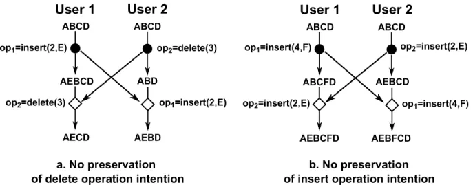
(11) 1.2.2. Commutative Replicated Data Type and TreeDoc. Commutative replicated data type (CRDT) [26] is a new approach that supports eventually consistent information. This approach focuses on designing data structures such that operations can commute with each other. Therefore, consistency is archived without concurrent control. TreeDoc [19] is a CRDT in which information is structured by a binary tree. With TreeDoc, the identifier of each node is its path on the tree. Furthermore, during the process of updating the tree, TreeDoc ensures that the path of each node is unique and not changed, so the different orders of the execution of concurrent operations lead the same state.. 1.3. Contributions. The main contribution of our work is the development of an Android-based application for decentralized collaborative editing based on the concept of TreeDoc. We have adapted TreeDoc to our need in document consistency management. Our application minimizes overhead of TreeDoc by developing rebalancing. In the evaluation, we carry out the the experiment on real environment with Android mobile devices to compare the performance of TreeDoc with Operational Transformation, an approach used by most of collaborative editing applications, and consider rebalancing with application performance in order to determine the most suitable value of rebalancing period. We provide a solution for fault tolerance in our application in order for a user who went too far outside of the transmission range of other devices can get missing messages when it has reconnected. By experiment, we investigate the effect of message loss probability to application performance.. 1.4. Thesis Organization. This thesis is organized in the chapters as follow: • Chapter 2 discusses the properties which the system must satisfy to ensure document consistency and Operation Transformation approach. • In chapter 3, we present document consistency management in our application with the concept of TreeDoc. • Chapter 4 is the implementation of our application. • The performance of our application is analyzed in Chapter 5. • Chapter 7 demonstrates the functions of our application. • Chapter 8 provides the conclusion of this thesis and the future work. 7.
(12) Chapter 2 Background 2.1. System Model. The system consists of a collection of users, each of which maintains a copy of the shared document containing a set of characters. User can make any operations on its local document whenever it wants. In order to enable all users to know the last state of the shared document, any operations generated by any users have to be broadcast to all other users. After receiving the remote operation, each user replays the remote operation on its own copy such that all copies of the shared document are consistent. Operations on the shared document are of two types: • Insert(posID,newchar) inserts a character newchar at position posID into the document • Delete(posID) deletes the character located by posID within the document. 2.1.1. Causality. For any pair of operations, opi and opj generated by user Si and Sj respectively, opi and opj can be either causally related or concurrent in the sense of the Lamport’s happened-before relation [11]. Definition 2.1. Causal precedence (→) opi causally precedes opj (opi → opj ) if: • opi and opj are generated by the same user (Si = Sj ) and opj is generated after opi . • opi and opj are generated by two different users (Si 6= Sj ) and Sj executed opi before generating opj . • There exists an operation opk , such that opi → opk and opk → opj . Definition 2.2. Concurrence (||) opi and opj are said to be concurrent (opi || opj ) if opi 9 opj and opj 9 opi 8.
(13) 2.1.2. State Vector. State vector [13] is a technique for capturing causal precedence among all operations in a system. It is a modification to the clock vector introduced by Mattern [18]. Definition 2.3. State vector Let us define the set of cooperative users in a system S1 , S2 ,..., SN . Each user Si in the system maintains a state vector which is a vector with N components Vi = (Vi [1], Vi [2],..., Vi [N]) in which Vi [j] holds the number of operations generated by user Sj that has been executed by user Si . In the beginning, Vi [j] = 0 with j=(1, ..., N). After Si executed an operation generated by user Sj , Vi [j] = Vi [j] + 1. Definition 2.4. Causal precedence with state vector opi generated by Si causally precedes opj generated by Sj (opi → opj ) if Vopi [i] < Vopj [i] where Vopi is the state vector of Si when it generates opi , Vopj is the state vector of Sj when it generates opj. 2.2. Document Consistency Properties. According to [7], a collaborative editing system is said to be consistent if it respects the following properties: Causality preservation property If opi causally precedes opj (opi → opj ), opi is executed before opj on all copies of the shared document. In other words, when a remote operation arrives at a user, it is executed only when all operations causally preceding it have been executed at that user. Figure 2.1 shows that when operations are executed in the same causal order, all copies are consistent, while Figure 2.2 shows otherwise.. User 1. User 2. User 3. ABCD. ABCD. ABCD. op1=insert(3,E). ABECD. op1=insert(3,E). ABECD. op1=insert(3,E). ABECD. op2=delete(2) op2=delete(2). op2=delete(2). AECD. AECD. AECD. Figure 2.1: Causality Presevation Property. 9.
(14) User 1. User 2. User 3. ABCD. ABCD. ABCD. op1=insert(3,E) op1=insert(3,E). ABECD. ABECD op2=delete(2) op2=delete(2). op2=delete(2). ACD. op1=insert(3,E). AECD. AECD. ACED. Figure 2.2: No Causality Presevation Property Intention preservation property The effect of an operation at all users must be the same as the intention of the user generated that operation. Operation intention for textual document is: • Delete: If a character is deleted on a copy, it must be deleted on all other copies. • Insert: A character inserted on a copy must be inserted on all other copies such that the order relation between it and other document characters is the same on all copies. The example in Figure 2.3a presents the case in which the intention of a delete operation is not preserved. In this example, user 1 and user 2 generate two concurrent operations op1 and op2 on the same object “ABCD”. User 1 generates op1 = insert(2,‘E’) with the intention of inserting ‘E’ between ‘A’ and ‘B’, and user 2 generates op2 = delete(3) with the intention of deleting ‘C’. However, when op2 is executed at user 1, deleted character is ‘B’, which is not the intention of op2 . That causes inconsistency. The example in Figure 2.3b presents the case in which the intention of a insert operation is not preserved. User 1 generates op1 = insert(4,‘F’) with the intention of inserting ‘F’ between ‘C’ and ‘D’, and concurrently, user 2 generates op2 = insert(2, ‘E’) with the intention of inserting ‘E’ between ‘A’ and ‘B’. However, when op1 is executed at user 2, ‘F’ is inserted between ‘B’ and ‘C’, which is not the intention of op1 . That causes inconsistency.. 10.
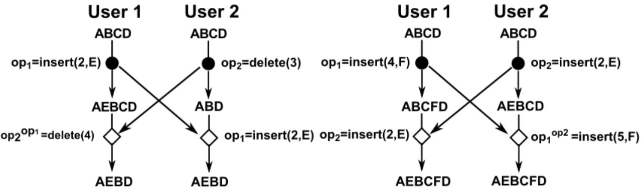
(15) User 1. User 2. User 1. User 2. ABCD. ABCD. ABCD. ABCD. op1=insert(2,E). op1=insert(4,F). op2=delete(3) ABD. AEBCD. op2=delete(3). ABCFD. op1=insert(2,E). AECD. op2=insert(2,E). AEBD. AEBCFD. a. No preservation of delete operation intention. op2=insert(2,E). AEBCD op1=insert(4,F). AEBFCD. b. No preservation of insert operation intention. Figure 2.3: No Intention Presevation Property. Convergence property After executing the same collection of operations, all users reach the same state. That is eventual consistency [12].. 2.3. Operational Transformation. Operational Transformation introduced by Ellis and Gibbs [13] with the DOPT algorithm is well established for concurrency control in group editing. Currently, many products use this approach such as Gobby, SubEthaEdit, ACE and most recently Google Wave. This approach manages the document by a sequential array of characters and uses the index of the character in the array for its posID. Using this approach, the local operation is executed immediately on local copy to ensure responsiveness, and then it is broadcast to all other users. When a user receives a remote operation, it is transformed against all of its concurrent operations in the history by forward transformation procedure before it is executed to preserve its intention. Consider the example in Figure 2.4, to preserve the intention, op2 in the example shown 1 in Figure 2.3a should be transformed forward against op1 to become opop = delete(4) 2 because after user 1 executes op1 , ‘C’ is in position 4 (Figure 2.4a), and op1 in the example shown in Figure 2.3b should be transformed forward against op2 to become 2 opop = insert(5,‘F’) because after user 2 executes op2 , the position between ‘C’ and ‘D’ 1 is position 5 (Figure 2.4b). 11.
(16) User 1. User 2. User 1. User 2. ABCD. ABCD. ABCD. ABCD. op1=insert(2,E). AEBCD op2op1 =delete(4). op2=delete(3). op1=insert(4,F). ABD. ABCFD op1=insert(2,E) op2=insert(2,E). AEBD. AEBCFD. AEBD. op2=insert(2,E). AEBCD op1op2 =insert(5,F). AEBCFD. b. Preservation of insert operation intention. a. Preservation of delete operation intention. Figure 2.4: Operational Transformation Specification 1 presents the forward transformation procedure. Specification 1 Forward Transformation Forward transformation of op1 = delete(posID 1 ) against op2 = delete(posID 2 ). 1: procedure fwtransform(op1, op2 ) 2: if posID 1 > posID 2 then 3: op1 = delete(posID 1 − 1); 4: end if 5: if posID 1 < posID 2 then 6: op1 = delete(posID 1 ); 7: end if 8: if posID 1 = posID 2 then 9: op1 = null; 10: end if 11: end procedure 12: 13: 14: 15: 16: 17: 18:. Forward transformation of op1 = delete(posID 1 ) against op2 = insert(posID 2 , newchar2 ). procedure fwtransform(op1, op2 ) if posID 1 ≥ posID 2 then op1 = delete(posID 1 + 1); else op1 = delete(posID 1 ); end if end procedure. 12.
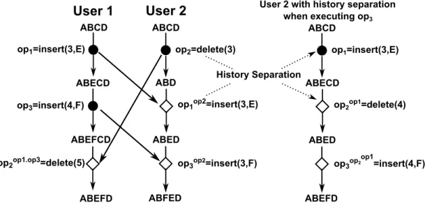
(17) 19: 20: 21: 22: 23: 24: 25: 26: 27: 28: 29: 30: 31: 32: 33: 34: 35: 36: 37: 38: 39: 40: 41: 42: 43: 44:. Forward transformation of op1 = insert(posID 1 , newchar1 ) generated by Sop1 against op2 = insert(posID 2 , newchar2 ) generated by Sop2 . procedure fwtransform(op1, op2 ) if posID 1 > posID 2 then op1 = insert(posID 1 + 1, newchar1 ); end if if posID 1 < posID 2 then op1 = insert(posID 1 , newchar1 ); end if if posID 1 = posID 2 then if newchar1 = newchar2 then op1 = null; else if Sop1 > Sop2 then op1 = insert(posID 1 , newchar1 ); else op1 = insert(posID 1 + 1, newchar1 ); end if end if end if end procedure Forward transformation of op1 = insert(posID 1 , newchar1 ) against op2 = delete(posID 2 ) procedure fwtransform(op1, op2 ) if posID 1 > posID 2 then op1 = insert(posID 1 − 1, newchar1 ); else op1 = insert(posID 1 , newchar1 ); end if end procedure. However, Ressel et al. in [14] showed that DOPT can not ensure document consistency in all cases. Concretely, inconsistent states happen when current operations are generated on different states. As depicted in Figure 2.5, user 1 generates op1 , op3 and user 2 generates op2 . When user 2 receives op1 , it transforms op1 against op2 because op1 ||op2 . Similarly, when user 2 receives op3 , it transforms op3 against op2 because op3 ||op2 and when user 1 receives op2 , it transforms op2 against op1 and op3 because op2 ||op1 and op2 ||op3 . However, in this case, two users are inconsistent after executing op1 , op2 , and op3 because transforming op3 against op2 at user 2 can not preserve the intention of op3 . That is because op1 and op2 are concurrent and generated on the same state, while although op3 is concurrent to op2 , they are generated on the different states. That is a typical case in the sense of partial concurrency [23] when an operation is concurrent to a sequence of operations.. 13.
(18) User 1. User 2. ABCD. ABCD. op1=insert(3,E). op2=delete(3) ABD. ABECD. op1op2=insert(3,E). op3=insert(4,F). ABEFCD. ABED. op2op1.op3=delete(5). op3op2=insert(3,F). ABFED. ABEFD. Figure 2.5: Inconsistency with Operational Transformation of DOPT Algorithm This problem is solved by SOCT2 [15]. Concretely, when a remote operation is executed at a user, SOCT2 uses backward transformation technique to shift all of its preceding operations backward to the beginning of the history and all of its concurrent operations to the end of the history. After separating history, the remote operation will be transformed forward against the set of its concurrent operations. Figure 2.6 presents how SOCT2 solves the inconsistent case in Figure 2.5.. User 1. User 2. ABCD. ABCD. op1=insert(3,E) ABECD. op3=insert(4,F). ABEFCD. op2op1.op3=delete(5). ABEFD. User 2 with history separation when executing op3 ABCD. op2=delete(3) History Separation. ABD. op1=insert(3,E) ABECD. op1op2=insert(3,E). ABED. op2op1=delete(4). ABED. op3op2=insert(3,F). ABFED. op3op2. op1. =insert(4,F). ABEFD. Figure 2.6: SOCT2 solves the Inconsistent Case in Operational Transformation of DOPT Algorithm Specification 2 presents the backward transformation procedure.. 14.
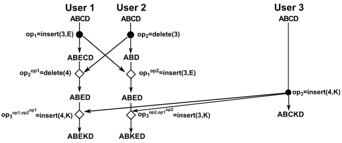
(19) Specification 2 Backward Transformation Backward transformation of op1 = delete(posID 1 ) against op2 = delete(posID 2 ). 1: procedure bwtransform(op1, op2 ) 2: if posID 1 ≥ posID 2 then 3: op1 = delete(posID 1 + 1); 4: else 5: op1 = delete(posID 1 ); 6: end if 7: end procedure. Backward transformation of op1 = delete(posID 1 ) against op2 = insert(posID 2 , newchar2 ). 8: procedure bwtransform(op1, op2 ) 9: if posID 1 > posID 2 then 10: op1 = delete(posID 1 − 1); 11: else 12: op1 = delete(posID 1 ); 13: end if 14: end procedure. 15: 16: 17: 18: 19: 20: 21: 22: 23: 24: 25: 26: 27: 28:. Back transformation of op1 = insert(posID 1 , newchar1 ) against op2 = insert(posID 2 , newchar2 ). procedure bwtransform(op1, op2 ) if posID 1 > posID 2 then op1 = insert(posID 1 + 1, newchar1 ); else op1 = insert(posID 1 , newchar1 ); end if end procedure Backward transformation of op1 = insert(posID 1 , newchar1 ) against op2 = delete(posID 2 ). procedure bwtransform(op1, op2 ) if posID 1 > posID 2 then op1 = insert(posID 1 + 1, newchar1 ); else op1 = insert(posID 1 , newchar1 ); end if end procedure. However, Vidot et al. in [16] indicated that SOCT2 is inconsistent under a scenario when concurrent operations are not performed in the same order at all users. Consider the example in Figure 2.7, when operation op3 generated by user 3 arrives at user 1 and user 2, it is transformed against its concurrent operations. Concretely, at user 1, op3 is transformed in turn against op1 and op2 , while at user 2, op3 is transformed in turn against op2 and op1 . Unfortunately, the results of transforming op3 at user 1 and user 2 are different, which causes to be inconsistent. Therefore, to reach consistent state, the result of transforming an operation against a sequence of its concurrent operations must not depend on the orders of the execution of those operations at all users.. 15.
(20) User 1. User 2. User 3. ABCD. ABCD. ABCD. op1=insert(3,E). ABECD. op2=delete(3). ABD. op2op1=delete(4). ABED. op1op2=insert(3,E). op1. op3op2,op1. op3op1,op2 =insert(4,K). ABEKD. op3=insert(4,K). ABED op2. ABCKD. =insert(3,K). ABKED. Figure 2.7: Inconsistency with SOCT2 In [16], Vidot et al. introduced SOCT3 to solve the inconsistent scenario of SOCT2 by an additional step to SOCT2. Concretely, like SOCT2 when a remote operation is received, it is transformed forward against the set of its concurrent operations obtained after the step of history separation. After that, operations in the history are rearranged by basing on the total ordering scheme by executing forward transformation and backward transformation. The rearrangement of the history after executing a remote operation ensures the order of operations in the history of all users to be the same. Figure 2.8 presents how SOCT3 solves the inconsistent case in Figure 2.7. User 1. User 2. ABCD. ABCD. op1=insert(3,E). User 2 with history rearrangement after executing op1. User 3. ABCD. ABCD. op1=insert(3,E). op2=delete(3) History rearrangement. ABECD op2. op1. =delete(4). ABED. ABD op1. ABECD op2. =insert(3,E). op2op1=delete(4) op3=insert(4,K). ABED. ABED. op1. op1. op3op1,op2. op3op1,op2 =insert(4,K). =insert(4,K). ABCKD. ABEKD. ABEKD. Figure 2.8: SOCT3 solves the Inconsistent Case in SOCT2 However, in SOCT3, the transformation procedure becomes very complex and errorprone [17]. Especially, with the large collaborative editing system in MANETs, many users and high network latency can cause a large number of concurrent operations while according this approach, every remote operation must be transformed against all of its concurrent operations to ensure document consistency. Therefore, it consumes a lot of 16.
(21) processing power, while the process power of mobile device is low. Consequently, it is not suitable for implementation on mobile device in the large collaborative editing application.. 17.
(22) Chapter 3 Document Consistency with TreeDoc In this chapter, we present TreeDoc [19], a commutative replicated data type that supports eventually consistent information. In our application, we have adapted the concept of TreeDoc to our need to ensure convergence and intention preservation properties and use state vector technique to preserve causality property.. 3.1. TreeDoc. TreeDoc [19] is a commutative replicated data type (CRDT) [26] designed for concurrent editing without concurrency control. It manages the document as a binary tree, and the content of document is defined by infix-order visit on the whole tree. Consider the example of Figure 3.1, the content of the document corresponding with TreeDoc is “ABCDEF”.. D. 0. 1. F. B 1. 0. A A. 0. E. C B. D. C. E. F. Figure 3.1: TreeDoc Instead of using an array to manage the document and the index of the character in the array for its identifier like Operational Transformation approach, in TreeDoc, the identifier of the character(posID) in the document is the path of the corresponding node in the tree. The path of node is a sequence of bit {0;1} in which 0 stands for left branch and 1 stands for right branch on the tree. For example, posID of node A; B; C; E in Figure 3.1 are 00; 0; 01; 10, respectively. 18.
(23) 3.1.1. Local Operation. When inserting a new character, the generator generates the corresponding node to the tree at the position such that the correlation between its position and the position of all other characters on the tree is guaranteed. After that, the generator sends inserted character and its identifier which is the path of the corresponding node to all other users. For example, to insert character X at right position of character D on the tree of Figure 3.1, because node D has right child, which is node F, node X is inserted at the leftmost position of the subtree rooted at node F, and then the generator gets the path of node X, which is 100. After executing that insert operation, the tree becomes the tree in Figure 3.2.. D. 0. 1. F. B 1. 0. A. 0. E. C 0. X C. B. A. X. D. E. F. Figure 3.2: TreeDoc after inserting X at right position of character D Another case is to insert character G at right position of character F on the tree of Figure 3.2. In this case, since node F has not right child, node G is right child of F as shown in Figure 3.3. 0. D. 1. F. B 1. 0. A. 1. 0. E. C. G. 0. X A. B. C. D. X. E. F. G. Figure 3.3: TreeDoc after inserting G at right position of character F When deleting a character, the generator sets the corresponding node to empty node and sends the path of the corresponding node on the tree to all other users. For example, 19.
(24) deleting character B in the tree of Figure 3.3 is executed by setting the corresponding node to empty node, and the tree becomes the tree of Figure 3.4. 0. D. 1. F 0. A. 1. 1. 0. E. C. G. 0. X A. C. D. X. E. F. G. Figure 3.4: TreeDoc after deleting B Specification 3 describes the procedures for generating node, applying local insert operation and local delete operation to TreeDoc. Specification 3 Application of local operation to TreeDoc Generation of new node N at right position node M 1: procedure GenerateNode(M) 2: if M has right child then 3: Create node N at the leftmost position of the subtree rooted at right child of node M; 4: else 5: Create node N is the right child of node M; 6: end if 7: return node N; 8: end procedure Application of locally deleting the character corresponding node N on tree 9: procedure ApplyLocalDeleteOperation(N) 10: Set node N to empty node; 11: Send the path of node N to all other users; 12: end procedure. 20.
(25) 13: 14: 15: 16: 17:. Application of locally inserting character newchar in right position of node M procedure ApplyLocalInsertOperation(M,newchar) Node N= GenerateNode(M); Set the content of node N to newchar; Send <the path of node N,newchar > to all other users; end procedure. 3.1.2. Remote Operation. When executing remote delete operation, user gets the node at the position corresponding with the identifier of deleted character on the tree, and sets it into empty node. When executing remote insert operation, user creates the node at the position on the tree corresponding with the identifier of inserted character, and sets its content into inserted character. Specification 4 describes the procedures for applying remote insert operation and delete operation to tree. Specification 4 Application of remote operation to TreeDoc Application of remote delete operation in which the path of deleted node is posID. 1: procedure ApplyRemoteDeleteOperation(posID) 2: Get node N whose path is posID 3: Set node N to empty node 4: end procedure Application of remote operation in which inserted character is newchar and path of inserted node is posID. 5: procedure ApplyRemoteInsertOperation(posID,newchar) 6: Create node N whose path is posID; 7: Set the content of node N to character newchar; 8: end procedure. 3.1.3. Commutative Replicated Data Type. For any pair of concurrent operations op1 and op2 , op1 is said to be commutative with op2 if on an initial state, both the execution of op1 before op2 and the execution of op2 before op1 result in the same state in which the intention of op1 and op2 are preserved. To prove that with the execution of update operation on TreeDoc under the way as above, two concurrent operations op1 and op2 can commute with each other, we investigate the following cases:. 21.
(26) Two concurrent insert operations (op1 = insert(posID 1 , newchar1 ), op2 = insert(posID 2 , newchar2 )). When a user finishes executing op1 and op2 , the share document contains both newchar1 and newchar2 . Because inserting a node to a tree does not change the path of all other nodes on that tree, posID 1 and posID 2 is unique and does not depend on the orders of the execution of op1 and op2 . In other word, the intention of op1 and op2 are always preserved. Hence, the final state is the same. Two concurrent delete operations (op1 = delete(posID 1 ), op2 = delete(posID 1 )) To delete a character on the document, TreeDoc sets the corresponding node on the tree to empty node, so executing delete operation does not change the path of all other nodes on the tree. Furthermore, the posID of a node on the tree is unique, so the existence of two nodes having the same posID is impossible. Therefore, after executing op1 and op2 , the share document does not contain deletedchar1 which is the deleted character of op1 and deletedchar2 which is the deleted character of op2 , and posID of all other characters is the same as before. In other words, the final state is the same. Concurrent delete operation and insert operation (op1 = delete(posID 1 ), op2 = insert(newchar2 , posID 2 )). As indicated above, the posID of a node on the tree is unique during the execution of insert and delete operation. After executing op1 and op2 , the share document includes newchar2 at the unique position posID 1 and does not contain deletedchar1 which is the deleted character of op1 . Therefore, the final state is the same.. 3.1.4. Rebalancing. Besides the advantages, TreeDoc has the problem of overhead. Firstly, during the execution of insert operations, the tree can become unbalanced, which causes the path of inserted node to grow indefinitely. For instance, if a user always appends to the end, the path of node will grow with each new character. Secondly, the tree can accumulate many empty nodes because of executing delete operations. To alleviate this problem, rebalancing is executed periodically to make the tree balanced and discard empty nodes. Rebalancing TreeDoc Rebalancing process creates a binary balanced tree whose document content is the same as document content of initial tree. Concretely, with initial tree corresponding to the document consisting of k characters, this process operates on the initial tree by generating nodes, removing nodes, assigning again the content of each node such that it becomes complete binary tree including k nodes, whose height is equal to ⌈log2 (k + 1)⌉-1, and document content is not changed. Figure 3.5 shows the example of rebalancing TreeDoc in Figure 3.5a to TreeDoc in Figure 3.5b. 22.
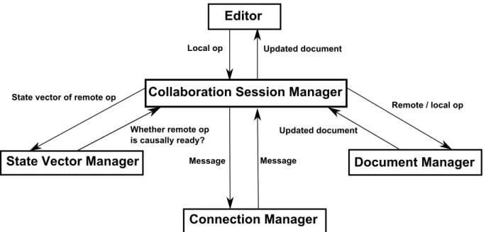
(27) D. C. F. B. Rebalancing B. D. A. E. C. E. G. F. A. G. a. TreeDoc before rebalancing. b. TreeDoc after rebalancing. Figure 3.5: Rebalancing TreeDoc Specification 5 describes the procedure for rebalancing TreeDoc. Specification 5 Rebalancing TreeDoc Rebalancing TreeDoc t 1: procedure Rebalance(t) 2: k= the number of nonempty nodes in t; 3: h = ⌈log2 (k + 1)⌉-1; 4: Visit t in infix order to create nodes, remove nodes to reach complete binary tree whose height is equal h, and assign again the content of t to be the same as before; 5: end procedure. Rebalancing TreeDoc in the large-scale system Although the sequential order of characters in the document is preserved after rebalancing, their identifiers is changed. Consequently, only updates on the copies executing rebalancing on the same state can be exchanged with each other. Therefore, before rebalancing tree, all users must agree on the same state of their trees by running a commitment protocol. However, it is difficult for commitment protocol to execute quickly, successfully in MANETs, which causes update operations to be blocked a long time. Two-tier architecture The solution for rebalancing tree in large-scale system is two-tier architecture introduced by Zawirski et al. in [20] in which all nodes are divided into two set, core set and nebular set: • The core set includes well-connected nodes. Only core nodes participate in commitment protocol. With above property of core set, commitment protocol is executed quickly. • Nebular set is dynamic, weakly connected, even disconnected. They only generate tree updates and do not participate in commitment protocol. 23.
(28) Every node defines an epoch e numbered sequentially for each rebalance. Rebalance in core set When a core node initiates rebalancing, it executes a commit protocol in which it plays the role of the coordinator to agree on the same final state in core set before executing rebalancing. If all core nodes agree on the same final state in epoch e, they execute rebalancing on that final state in epoch e to create the initial state in epoch e + 1. Rebalance in nebular set Because nebular nodes are not allowed to participate in commitment protocol for rebalancing, after core nodes execute rebalancing, nebula nodes are behind with core nodes at one or more epochs. Consequently, all updates generated by nebular nodes cannot be replayed at core nodes, although they can be replayed on all other nebular nodes in the same epoch. The catch-up protocol updates a nebula node to the next epochs. Catch-up protocol When a nebular node N in epoch e contacts a node C in epoch e + 1, N executes catchup protocol to update its copy. Concretely, C sends all updates in epoch e to N. After receiving all updates in epoch e, noted by ue , from C, N applies ue to the initial state in epoch e to create the final state in epoch e and executes rebalancing on the final state in epoch e to create initial state in epoch e + 1. After that, N translates updates which it executed in epoch e but not belong to ue into epoch e + 1, then applies and broadcasts them. Specification 6 describes the procedure for catching up. Specification 6 Catching up nebular node in epoch e to epoch e+1 Catching-up nebular node N in epoch e after receiving all update in epoch e, noted by ue , from node C in epoch e + 1 1: procedure Catch-up(ue ) 2: Apply ue to the initial state in epoch e to reach the final state in epoch e; 3: Rebalance the final state in epoch e to create the initial state in epoch e + 1; 4: Translate updates which is not in ue into epoch e + 1, then apply and send them to all other user; 5: end procedure. 3.2. Causality Preservation with State Vector. When a user updates its local copy, it sends the operation to all other users with the current value of its local vector. In [13], if each component of the state vector Vi , which is the state vector of user Si , is greater than or equal to the corresponding component of the state vector Vj , which is the state vector of user Sj , user Si has already executed 24.
(29) all operations that have been executed by user Sj . Furthermore, to preserve causality property, when a remote operation op arrives at user Si , op is only executed if all operations causally preceding it have already been executed by user Si . Consequently, user Si only executes op when each component of its state vector is greater than or equal to the corresponding component of the state vector Vop . Specification 7 presents the procedures for executing local operation and remote operation to preserve causality property by state vector technique. Specification 7 Causality Preservation with State Vector technique Execution of local operation op at user Si with state vector Vi . 1: procedure ExecuteLocalOperation(op) 2: ApplyLocalOperation(op); 3: Vop = Vi ; 4: Vi [i] + +; 5: Send <op,Vop > to all other user; 6: end procedure Execution of remote operation op with state vector Vop generated by user Sj at user Si with state vector Vi . 7: procedure ExecuteRemoteOperation(op,Vop ,Sj ) 8: if Vi [k] ≥ Vop [k] , (k: 1 ≤ k ≤ N) then 9: ApplyRemoteOperation(op); 10: Vi [j] + +; 11: else 12: Wait until Vi [k] ≥ Vop [k] ,(k: 1 ≤ k ≤ N); 13: end if 14: end procedure. 25.
(30) Chapter 4 Implementation 4.1. System Architecture. In this section, we present the system architecture for every collaborative user. Each collaborative user consists of the following components as shown in Figure 4.1:. Editor Local op. Updated document. Collaboration Session Manager. State vector of remote op. Remote / local op Whether remote op is causally ready?. State Vector Manager. Updated document. Message. Message. Document Manager. Connection Manager Figure 4.1: System Architecture • Document manager is responsible for applying local operation/remote operation on the document structure, then returning new content of the document. In order to edit, rebalance in the collaboration, document management of user Si in epoch n has to include as follow: – For ensuring document consistency on current document, current state xn , structured by TreeDoc, is required. 26.
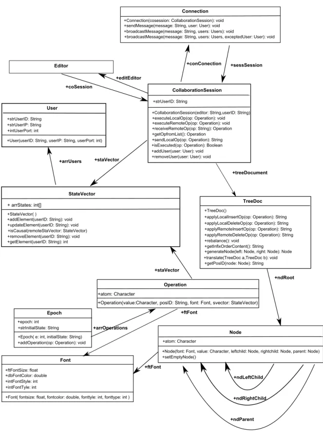
(31) – For helping other users to perform catch-up protocol to update their documents to epoch n, Si has to keep all operations that it executed before. – If Si is a nebular user, in the future, it will perform catch-up protocol to update its document to the document in the epoch of core set. In order to do that, a nebular user in epoch n needs to keep the initial state and all operations that it is executed in the epoch n. Because the initial state of an epoch is balanced tree, it is managed by an array structure of characters to reduce overhead. • State vector manager is responsible for determining whether remote operation is causally ready. • Collaboration session manager is responsible for managing the entire collaboration. Concretely, when it receives a message related to the remote operation, it forwards state vector to state vector manager, operation to document manager, and the new content of the document to editor after executing the remote operation. Furthermore, when it receives local operation from editor, it forwards operation to document manager, updates state vector, and sends message related to that local operation to all other users through connection manager. • Connection Manager is responsible for sending and receiving messages to and from all other uses • Editor is the tool for editing the shared document.. 4.2. Class Diagram. Figure 4.2 shows the class diagram of our collaborative editing application. In general, TreeDoc structure contains a Node root. Node in TreeDoc includes: • atom is the character corresponding with the node • leftChild is left child node • rightChild is right child node • parent is parent node. • Font is the font of the node In a Node, Font consists: • fontStyle are Bold, Italic, Underline, Quote, Strike-through. • fontType are Normal, Monospace, Serif, Sans-Serif. • fontSize is the size of the character. • fonttextColor is the color of the character. 27.
(32) • fontbgColor is the color of background of the character. StateVector is structured by an array of states corresponding with an array of users in the system. When a remote operation is causally ready, the state corresponding with the user generating that operation will be incremented. Epoch contains a list of executed operations to perform catch-up protocol in the future.. 28.
(33) Connection +Connection(cosession: CollaborationSession): void +sendMessage(message: String, user: User): void +broadcastMessage(message: String, users: Users): void +broadcastMessage(message: String, users: Users, exceptedUser: User): void. +conConection. Editor. +sessSession. +editEditor +coSession. CollaborationSession +strUserID: String. User +strUserID: String +strUserIP: String +intUserPort: int +User(userID: String, userIP: String, userPort: int). +arrUsers. +staVector. +CollaborationSession(editor: String,userID: String) +executeLocalOp(op: Operation): void +executeRemoteOp(op: Operation): void +receiveRemoteOp(op: String): Operation +getOpfromList(): Operation +sendLocalOp(op: Operation): String +isExecuted(op: Operation): Boolean +addUser(user: User): void +removeUser(user: User): void. +treeDocument. StateVector TreeDoc. + arrStates: int[]. +TreeDoc() +applyLocalInsertOp(op: Operation): String +applyLocalDeleteOp(op: Operation): String +applyRemoteInsertOp(op: Operation): String +applyRemoteDeleteOp(op: Operation): String +rebalance(): void +getInfixOrderContent(): String +generateNode(left: Node, right: Node): Node +translate(TreeDoc a,TreeDoc b): void +getPosID(node: Node): String. +StateVector( ) +addElement(userID: String): void +updateElement(userID: String): void +isCausal(remoteStaVector: StateVector) +removeElement(userID: String): void +getElement(userID: String): int. +staVector +ndRoot Operation +atom: Character +Operation(value:Character, posID: String, font: Font, svector: StateVector). +ftFont. Epoch +epoch: int +strInitialState: String. +arrOperations. Node. +Epoch( e: int, initialState: String) +addOperation(op: Operation): void. +atom: Character +Node(font: Font, value: Character, leftchild: Node, rightchild: Node, parent: Node) +setEmptyNode(). Font +ftFont. +ftFontSize: float +dbFontColor: double +intFontStyle: int +intFontTyle: int. +ndLeftChild. +Font( fontsize: float, fontcolor: double, fonttyle: int, fonttype: int ). +ndRightChild. +ndParent. Figure 4.2: Class Diagram. 29.
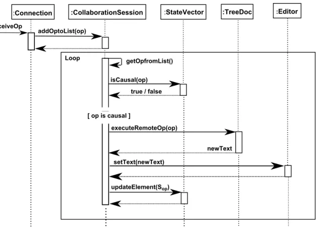
(34) 4.3. Sequence Diagram. Figure 4.3 shows the sequence diagram for the process of a local operation. Concretely, when user Si edits a character on local Editor , CollaborationSession gets that operation (op) from Editor , applies it to TreeDoc, and updates the element related to user Si in StateVector . Finally, op and state vector of Si when it generates op is sent asynchronously to all other users though Connection.. :Editor. User Si. :CollaborationSession. :TreeDoc. :StateVector. :Connection. Edit() executeLocalOp(op) applyLocalOp(op). posID updateElement (Si). asyncSend(op,Vop). Figure 4.3: Sequence Diagram for the process of Local Operation Figure 4.4 shows the sequence diagram for the process of a remote operation. When Connection receives a remote operation from other user, it is added to a list of operations that is waiting for be executed. CollaborationSession gets a operation from the list of operations, checks whether it is causally ready, and execute it on TreeDoc in the case of causal condition. After that, CollaborationSession sets the new content of the shared document to Editor .. 30.
(35) :Connection ReceiveOp. :CollaborationSession. :StateVector. :TreeDoc. :Editor. addOptoList(op). Loop. getOpfromList() isCausal(op) true / false. [ op is causal ] executeRemoteOp(op) newText setText(newText). updateElement(Sop). Figure 4.4: Sequence Diagram for the process of Remote Operation. 31.
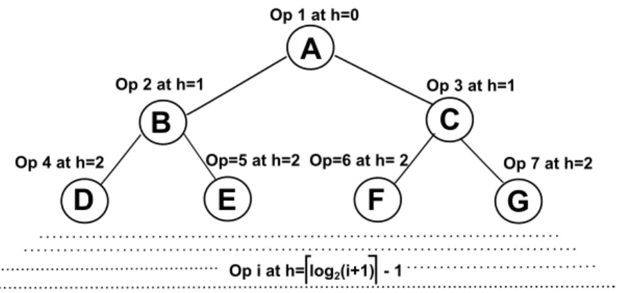
(36) Chapter 5 Evaluation In this chapter, we compare the performance of two approaches for ensuring document consistency, TreeDoc and Operational Transformation in SOCT3 [16]. After that, we investigate the effect of rebalancing to the performance of TreeDoc. In Operational Transformation approach, each remote operation must be transformed against all its concurrent operations in the history to preserve its intention. Therefore, operation time of this approach depends on the number of concurrent operations in the system. In contrast to Operational Transformation, using TreeDoc, concurrent operations can commute with each other. Consequently, operation time of TreeDoc does not depend on the number of concurrent operations in the system and only depends on editing context of every operation. Concretely, in TreeDoc, time for executing local operation depends on time for walking on tree from the corresponding node to root to get posID, while time for executing remote operation depends on time for walking on tree from root to the node corresponding with posID. In other words, operation time of TreeDoc depends on the height of the node corresponding with every operation. Furthermore, total height of all nodes on the tree is minimal if the tree is always balanced during the execution of operations (operation i at height h=⌈log2 (i + 1)⌉-1, i = 1...n) like Figure 5.1. That is the best case for operation time of TreeDoc. The worst case for operation time of TreeDoc is the case of only editing at a certain position. In that case, the height of node increases steadily during the execution of operations (operation i at height h = i − 1, i = 1...n) like Figure 5.2, and total height of all nodes on the tree tree is maximal.. 32.
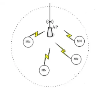
(37) Op 1 at h=0. A Op 2 at h=1. Op 3 at h=1. C. B Op=5 at h=2 Op=6 at h= 2. Op 4 at h=2. D. E. Op 7 at h=2. F. G. Op i at h= log2(i+1) - 1. Figure 5.1: Best Case of TreeDoc: the tree is balanced, the depth is logarithmic Op 1 at h=0. A Op 2 at h=1. B Op 3 at h= 2. C Op=i at h=i-1. I Figure 5.2: Worst Case of TreeDoc: the tree degenerates as a list with every new character added to the right, the depth is linear.. 5.1. Experiment Setting. We experiment on 4 real android device Samsung GT-I9250 Galaxy Nexus (CPU speed: 1.2 GHz Dual Core Processor; Internal phone storage: 16GB; RAM: 1GB; OS version: Android OS 4.0). Because Android 4.0 does not officially build the ability to connect to ad-hoc networks, in our experiments, every mobile device is connected with each other by wireless network in which AirMac Extreme 802.11n Wi-Fi is the based station as shown in Figure 5.3. All mobile devices are located at the same position, and we use Ping command, we estimate network delay in this position by 77 ms.. 33.
(38) Figure 5.3: Experimental Environment In our experiments, every device begins with the empty shared document as presented in Figure 5.4 and generates 250 operations. Therefore, every device will execute 1000 operations consisting of 250 local operations generated by it and 750 remote operations generated by all other devices. Figure 5.5 shows a consistent state of all devices after experiment. In every experiment, we get 30 measurements of each sample.. Figure 5.4: The Empty State in the Begining of Experiment. 34.
(39) Figure 5.5: Consistent State in the End of Experiment. 5.1.1. Operation Time. Firstly, we consider average operation time for a device to finish all operations as shown in Figure 5.6 (operation time = time for executing 250 local operations + time for executing 750 remote operations) in 4 cases: • Operational Transformation • The best case of TreeDoc • The worst case of TreeDoc without rebalancing • The average case of TreeDoc where editing positions are generated randomly in uniform distribution without rebalancing Receive remote op Operation time. User. Present to editor. Execute local op. Execute remote op. Present to editor. Operation time Broadcast local op. Figure 5.6: Operation Time In this experiment, we manipulate the number of concurrent operations in the system by increasing operation interval, that is the period between two consecutive operations, in 35.
(40) order to investigate the trend of operation time when the number of concurrent operations increases. Because every operation carries the state vector to reflect the status of the user generated it, we base on the state vector of every operations to compute the number of current operations in the system. Figure 5.7 shows the result of this experiment. The number of concurrent operations decreases as operation interval increases, which results in the decrease of operation time of Operational Transformation, while operation time of TreeDoc is not changed. That is because for Operational Transformation, the more the number of concurrent operations is, the more the transformation procedure is executed, while for TreeDoc, concurrent operations can commute with each other without control. Especially, when operation interval is close to or greater than network delay, the number of current operations is fixed by 4 operations and operation time of Operational Transformation is 1553.3 ms. In the best case, operation time of TreeDoc is 457.57 ms, that is always better than operation time of Operational Transformation. However, in the worst case, operation time of TreeDoc is 3571.63 ms, that is only better than operation time of Operation Transformation if the number of current operations is greater than 10 operations. 10 Operational Transformation The Worst Case of TreeDoc without Rebalancing The Average Case of TreeDoc without Rebalancing The Best Case of TreeDoc. Operation Time (s) for 1000 Operations. 9 8 7 6 5 4 3 2 1 0. 10 (24). 20 25 30 (12) (10) (8). 40 50 60 70 (6) (5) (4) (4) Operation Interval(ms) (The Number of Concurrent Operation). 80 (4). 90 (4). 100 (4). Figure 5.7: The number of Concurrent Opertions vs. Operation Time without Rebalancing. 36.
(41) 5.1.2. Rebalancing Time. With periodically executing rebalancing, the height of tree decreases, which results in the decrease of operation time in the worst case of TreeDoc. Next, we consider rebalancing time, operation time (2 cores, 2 nebulars) as depicted in Figure 5.8 in the worst case of TreeDoc when manipulating rebalancing period, that is the number of operations for a repeating rebalancing. Receive remote op. User. Present to editor. Operation time. Rebalancing time. Execute local op. Rebalance. Execute remote op Present to editor Operation time. Rebalance Rebalancing time. Broadcast local op. Figure 5.8: Rebalancing Time The more the execution of rebalancing is, the more operation time decreases (Figure 5.9). However, the more the execution of rebalancing is, the more rebalancing time increases (Figure 5.9). With rebalancing period of 200 operations, total time consisting of rebalancing time and operation time is minimal (Figure 5.9) and operation time in the worst case of TreeDoc is reduced by 1100.26 ms that is always better than operation time of Operational Transformation (Figure 5.10). Therefore, 200 operations is the best value of rebalancing period in our experiments. 5000 4500. Operation Time Rebalancing Time Total Time= Operation Time + Rebalancing Time. Time (ms) for 1000 Operations. 4000 3500 3000 2500 2000 1500 1000 500 0. 50 100 150 200 250 300 400 500 600 Rebalancing Period ( # of Operation). 700. 800. Figure 5.9: The Worst Case of TreeDoc vs. Rebalancing. 37. 900.
(42) 10 Operational Transformation The Worst Case of TreeDoc with Rebalancing Period=200 The Average Case of TreeDoc with Rebalancing Period=200 The Best Case of TreeDoc (Rebalancing is not needed). Operation Time (s) for 1000 Operations. 9 8 7 6 5 4 3 2 1 0. 10 (24). 20 (12). 30 (8). 40 (6). 50 60 70 (5) (4) (4) Operation Interval(ms) (The Number of Concurrent Operation). 80 (4). 90 (4). 100 (4). Figure 5.10: Operation Time vs. The number of Concurrent Opertions with Rebalancing. 5.1.3. Operation Latency. Next, we consider latency of every operation, that is the interval from the time when a user edits a character on its editor to time when other user takes effect of that character like Figure 5.11. Operation Latency. User 1. Present to editor. Execute local op. Broadcast local op. Receive remote op. Execute remote op Present to editor. User 2. Figure 5.11: Operation Latency In the worst case of TreeDoc, latency of every operation increases with operation ID because the height of the node corresponding with every operation increases steadily (operation i at height h = i − 1, i = 1...n). However, with rebalancing period of 200 operations, rebalancing is executed at operation ID:200; 400; 600; 800, which leads the 38.
(43) height of nodes corresponding with operation ID: 201;401;601;801 to be reduced by 7;8;9;9, respectively and the decrease of nodes corresponding with operations after rebalancing. Therefore, latency falls dramatically after rebalancing as shown in Figure 5.12, and the maximum of operation latency is 146.4 ms. 250. Operation Latency (ms). 200. 150. 100. 50. 0 1 (0). 100 (99). 200 (199). 300 (106). 400 500 600 (206) (107) (207) Operation ID (The Height of Related Node). 700 (108). 800 (208). 900 (108). 1000 (208). Figure 5.12: The Worst Case of TreeDoc vs. Operation Latency. 5.1.4. Time Usage. Finally, Figure 5.14 shows time usage of a user during the collaboration session with rebalancing period of 200 operations and operation interval of 100 ms. Completion time is average time for a user to finish the collaboration session. It includes the following components as presented in Figure 5.13: • Present time is time for updating editor • Operation time is time for executing local/remote operation • Rebalancing time is time for executing rebalancing • Idle time. 39.
(44) User. Present time. Operation time. Rebalancing time. Present to editor. Execute local op. Rebalance. Idle time Idle. Operation time. Present time. Execute remote op Present to editor. Rebalancing time Rebalance. Figure 5.13: Completion Time In the best case of TreeDoc, the tree is always balanced during the collaboration session, so it does not need rebalancing. Furthermore, in this case, operation time is minimal because total height of all nodes in the tree is minimal. Therefore, process time of this case only consists of present time and operation time and is relatively small at 3.3% (operation time=1.8%; present time=1.5%; rebalancing time=0%) of completion time. Conversely, in the worst case of TreeDoc, the tree has to be periodically rebalanced to reduce operation time. Hence, process time of this case consists of present time, operation time, and rebalancing time. In this case, process time is the largest of three cases of TreeDoc and up to 7.3% (operation time=4.4%; present time=1.5%; rebalancing time=1.4%) of completion time. 100. Operation time Rebalancing time Present time Idle time. Utilization (%). 80. 60. 40. 20. 0. Worst. Average The cases of TreeDoc. Best. Figure 5.14: Time Usage of a User during the Collaboration Session. 40.
(45) Chapter 6 Fault Tolerance 6.1. Disconnection. In MANETs, mobile device frequently gets disconnected from other devices. In the scope of this thesis, we concentrate on the disconnection in the case when mobile device goes too far out of the transmission range of other devices. When a site is disconnected, it can not receive and broadcast messages from/to sites that it is disconnected. Consequently, in the collaboration session, not only disconnected user misses messages but also other users miss messages generated by disconnected user during disconnection period. Because of disconnection event, every user in the collaboration session has its own state which may be different from the state of other users. Therefore, when a user joins the collaboration session, it may miss some document operations to reach the last state of the collaboration session. Furthermore, when a user joins the collaboration session, if a current user in the collaboration session is disconnected from the joining user, it will miss the joining message broadcast by the joining user and document operations generated by the joining user before joining the collaboration session. Furthermore, collaboration session has to ensure causality preservation property. Consequently, a message may be blocked at a user, if that user misses messages causally preceding it. In order to tolerate disconnection event, the system has to solve missing messages (operation document, leaving, joining). Concretely, the system must satisfy the following property: • If a user Si generates a message m (operation document, leaving, joining), eventually, all users receive m either directly from Si or indirectly from other users.. 6.2. Related Works. One approach is that all users have to agree on the same state when a user joins the collaboration session. Therefore, joining user is able to get the last state of the share document easily and all current users in the collaboration session do not miss joining 41.
(46) message and document operation messages generated by joining user before joining the collaboration session. Concretely, in Ycab [21], all users agree on the same state by running commitment protocol in which joining user is the coordinator. Concretely, when a user joins the collaboration session, it broadcasts joining message and its current state to all users of the collaboration session and waits for the replies about their states. If all users have the same state, joining users broadcasts the message to notify all users of processing joining messages and adding joining user to their participant list. Contrary to Ycab, in CoWord [22], all users agree on the same state by broadcasting synchronization message to push all operations to arrive, be executed at their destinations, and temporarily block users from generating new operations, which is called quiescence state. If all users reach quiescence state, they have identical document state. Therefore, in order to join the collaboration session successfully, joining user only needs to get the document and state vector of a current user. This approach requires all users to be well-connected together during the process of joining session to ensure that all messages arrive at their destinations. Therefore, the agreement is executed correctly, quickly and the collaboration session is not blocked a long time. However in MANETs, above condition is not always guaranteed. In this chapter, we will provide a solution to solve missing message problem for the process of joining, leaving, editing in a collaboration session.. 6.3. Tolerating Missing Messages. Each message in a collaboration session consisting of joining message, document operation message, leaving message has to carry a state vector to reflect the status of the user generated it. For each user, the first message is a joining message, the next messages are document operation messages, and the last message is a leaving message. In the collaboration session, every user has to ensure the execution of those messages in causal order by basing on their state vectors to detect which of the message is causally ready. Consequently, when a message m generated by user Si arrives user Sj , Sj compares the state vector of m, which shows the state of Si when it generated m, and the state vector of Sj , which shows the state of Sj when m arrives Sj , in order to detect message k that causally precedes m and Sj misses, and then, Sj sends a request to ask Si to resend missing message k. The following sections discuss how user Sj detects missing message by comparing its state vector and the state vector of received message m generated by user Si in two cases. After that, we specify two error cases in which the comparison between state vectors cannot detect missing message and provide solutions for those cases.. 6.3.1. Detection in the Normal Case. In this case, Sj detects missed messages generated by user St whose related component appears in both the state vector of Sj , noted by VSj , and the state vector of message m, 42.
(47) noted by Vm . As described in the section 2.3, VSj [St ] indicates the number of messages generated by St that has already been executed by Sj , while Vm [St ] indicates the number of messages generated by St that has already been executed by user Si when it generates m. Therefore, if Vm [St ] is greater than VSj [St ], Sj realizes that it misses messages k=< Vm [St ]-1,Vm [St ]-2,....,VSj [St ] > generated by St . Figure 6.1 shows the example in which user Sj is disconnected from St , Si . Therefore, Sj can not receive opSt0 , opSi0 generated by St , Si , respectively during disconnection period of Sj . When Sj reconnects, it receives opSi1 generated by Si . By basing on state vector of opSi1 , that is state vector of Si when it generates opSi1 , Sj knows that Si has already executed one operation generated by St because VSi [St ] = 1 and one operation generated by Si because VSi [Si ] = 1, while Sj has yet to execute any operations generated by St and Sj . Consequently, Sj detects missing messages consisting of message 0 generated by St (opSt0 ), message 0 generated by Si (opSi0 ), and sends a request to ask Si to resend those messages.. Site St. Site Sj. Site Si. VSt( St=0, Si=0, Sj=0) <opSt0, VSt>. VSi( Si=0, St=0,Sj=0). VSt( St=1, Si=0, Sj=0). VSi( Si=0, St=1,Sj=0). VSj( Sj=0, St=0,Si=0). <opSi0, VSi>. VSt( St=1, Si=1,Sj=0). VSi( Si=1, St=1,Sj=0). <opSi1, VSi>. VSt( St=1, Si=2,Sj=0). VSi( Si=2, St=1,Sj=0). Compare VSi(Si=1,St=1,Sj=0) with VSj(Sj=0,St=0,Si=0) to detect missing message: + Message 0 genereted by St + Message 0 generated by Si. Figure 6.1: Detection in the Normal Case. 6.3.2. Detection in the Special Case: Missing Joining or Leaving Messages. In this case, Sj detects missing messages generated by St whose related component appears in state vector of Sj and disappears in state vector of message m. This case happens because two reasons: • The first reason is that Si executed joining message of St before generating m, while Sj missed joining message of St . In this case, Sj misses all of message generated by 43.
(48) St : < Vm [St ]-1,Vm [St ]-2,...,0 >. This context is shown in the example in Figure 6.2. In this example, when receiving opSi0 generated by Si , Sj knows that it misses all messages generated by St consisting of joining message and opSt1 of St . Site St VSt( St=0, Si=0, Sj=0) <JoiningSt0, VSt>. VSt( St=1, Si=0, Sj=0). Site Sj. Site Si. VSj( Sj=0, Si=0). VSi( Si=0, Sj=0). VSi( Si=0, Sj=0, St=1). <opSt1, VSt>. VSt( St=2, Si=0, Sj=0). VSi( Si=0, Sj=0, St=2) <opSi0, VSi>. VSt( St=2, Si=1, Sj=0). VSi( Si=1, Sj=0, St=2). Compare VSi( Si=1,Sj=0, St=2) with VSj(Sj=0,Si=0) to detect missing message: + Message 0 genereted by St + Message 1 generated by St. Figure 6.2: Detection in the Special Case: Missing Joining Messages • The second reason is that Si missed leaving message of St before generating m, while Sj executed leaving message of St . In this case, Sj does not miss any messages generated by St . Consider the example in Figure 6.3, when receiving opSi0 generated by Si , Sj knows that it does not miss any messages generated by St because it executed leaving message of St . Site St VSt( St=0, Si=0, Sj=0) <opSt0, VSt>. VSt( St=1, Si=0, Sj=0). Site Si VSi( Si=0, St=0, Sj=0). VSi( Si=0, St=1,Sj=0). Site Sj VSj( Sj=0, St=0, Si=0). VSj( Sj=0, St=1, Si=0). <leavingSt1, VSt>. <opSi0, VSi >. VSj( Sj=0, Si=0). No missing message VSi( Si=1, St=1,Sj=0) VSj( Sj=0, Si=1). Figure 6.3: Detection in the Special Case: Missing Leaving Messages Specification 8 describes the procedure for detecting missing messages.. 44.
(49) Specification 8 Detection of Missing Messages Sj with state vector VSj detects missing message after receiving message m with state vector Vm generated by Si . 1: procedure DectectMissingMessages(m,Vm,Si ) 2: for all St ∈ Vm do 3: if St ∈ VSj then 4: if VSj [St ] < Vm [St ] then 5: Send a request to Si for asking missing messages k=< Vm [St ]−1, Vm [St ]− 2, ..., VSj [St ] >; 6: end if 7: else 8: if Sj already executed leaving message of St then 9: No missing messages; 10: else 11: Send a request to Si for asking missing messages k=< Vm [St ]−1, Vm [St ]− 2, ..., 0 >; 12: end if 13: end if 14: end for 15: end procedure. 6.3.3. Fault Case 1: Missing All Messages from a User. Consider the context in Figure 6.4 where user Sj misses all messages (joining, operation, leaving) generated by St from the time when St joins the collaboration to the time when St leaves the collaboration, while user Si receives and executes all of those messages. In this context, when message opSi0 generated by Si arrives Sj , Sj can not detect missing messages generated by St by comparing its state vector with state vector of Si because now, the component associated with St is no longer in state vector of Si after Si executed leaving message of user St .. 45.
(50) Site St VSt( St=0, Si=0, Sj=0) <JoiningSt0, VSt>. VSt( St=1, Si=0, Sj=0). Site Si. Site Sj. VSi( Si=0, Sj=0). VSj( Sj=0, Si=0). VSi( Si=0, St=1,Sj=0). <opSt1, VSt>. VSt( St=2, Si=0, Sj=0). VSi( Si=0, St=2,Sj=0). <LeavingSt2, VSt>. VSi( Si=0, Sj=0) <opSi0, VSi>. Can't detect missing message generated by St by compare VSi(Si=0,Sj=0) with VSj(Sj=0,Si=0). Figure 6.4: Fault Case when Missing All Messages from a User In order to take into account this context, Si has to delay executing leaving message until it generates a message. Concretely, in Figure 6.5, after receiving leaving message of St , Si does not execute that leaving message immediately. After Si generates message opSi0 and sends it to all other users, Si executes leaving message of St by removing St from its state vector. Consequently, when Sj receives message opSi0 , it can detect missing messages generated by St because the component associated with St is still in the state vector of opSi0 . In the worst case where Sj misses message opSi0 , although the next messages generated Si do not help Sj to detect missing messages generated by St , they help Sj to detect missing message opSi0 and after that, Sj bases on state vector of opSi0 to detect missing messages generated by St . Site St VSt( St=0, Si=0, Sj=0) <Joiningst0, VSt>. VSt( St=1, Si=0, Sj=0). Site Si. Site Sj. VSi( Si=0, Sj=0). VSj( Sj=0, Si=0). VSi( Si=0, St=1,Sj=0). <opst1, VSt>. VSt( St=2, Si=0, Sj=0). VSi( Si=0, St=2,Sj=0). <Leavingst2, VSt>. VSi( Si=0, St=3, Sj=0) <opsi0, VSi>. Compare VSi(Si=0,St=3,Sj=0) with VSj(Sj=0,Si=0) to detect missing message: + Message 0,1,2 generated by St. VSi( Si=1, Sj=0). Figure 6.5: Solution for Fault Case 1. 46.
図
+7

関連したドキュメント
It is suggested by our method that most of the quadratic algebras for all St¨ ackel equivalence classes of 3D second order quantum superintegrable systems on conformally flat
[11] Karsai J., On the asymptotic behaviour of solution of second order linear differential equations with small damping, Acta Math. 61
By employing the theory of topological degree, M -matrix and Lypunov functional, We have obtained some sufficient con- ditions ensuring the existence, uniqueness and global
Using the T-accretive property of T q in L 2 (Ω) proved below and under additional assumptions on regularity of initial data, we obtain the following stabilization result for the
Then it follows immediately from a suitable version of “Hensel’s Lemma” [cf., e.g., the argument of [4], Lemma 2.1] that S may be obtained, as the notation suggests, as the m A
Definition An embeddable tiled surface is a tiled surface which is actually achieved as the graph of singular leaves of some embedded orientable surface with closed braid
Correspondingly, the limiting sequence of metric spaces has a surpris- ingly simple description as a collection of random real trees (given below) in which certain pairs of
The important dynamical difference between the transient AIDS state in the acute infection stage and the chronic AIDS state that signals the end of the incubation period is the value
