Japan Advanced Institute of Science and Technology
Title Automatic translation from name-based pointcuts to analysis-based pointcuts for robust aspects
Author(s) 王, 林
Citation
Issue Date 2011-09
Type Thesis or Dissertation Text version author
URL http://hdl.handle.net/10119/9932 Rights
Description Supervisor: Professor Koichiro Ochimizu, Information Science, Master
analysis-based pointcuts for robust aspects
By Lin Wang
A thesis submitted to
School of Information Science,
Japan Advanced Institute of Science and Technology,
in partial fulfillment of the requirements
for the degree of
Master of Information Science
Graduate Program in Information Science
Written under the direction of
Professor Koichiro Ochimizu (JAIST)
Professor ZhiYong Feng (TU)
By Lin Wang (0910216)
A thesis submitted to
School of Information Science,
Japan Advanced Institute of Science and Technology,
in partial fulfillment of the requirements
for the degree of
Master of Information Science
Graduate Program in Information Science
Written under the direction of
Professor Koichiro Ochimizu (JAIST)
Professor ZhiYong Feng (TU)
and approved by
Professor Koichiro Ochimizu (JAIST)
Associate Professor Masato Suzuki (JAIST)
Associate Professor Toshiaki Aoki (JAIST)
Professor ZhaoPeng Meng (TU)
Associate Professor YiKui Zhang (TU)
August, 2011 (Submitted)
Separation of concerns(SoC) is an important principle in software engineering. With-out it large software system simply could not be realized. Aspect-Oriented program-ming(AOP) improves SoC by modularizing crosscutting concerns. Unfortunately todays mainstream AOP languages suffer from fragile pointcut problem. They are fragile be-cause they break easily if the names of the methods or classes are changed when program evolved. We compared several important researches which attempt to solve pointcut fragility, and observed that new pointcut languages are very different from original one, so they are difficult to be written by a programmer.
In this dissertation we propose a framework called Nataly, which translates name-based pointcuts into analysis-name-based pointcuts automatically. Our approach can not only alleviate pointcut fragile problem but also bridge a gap between original name-based pointcut and other robust one. Name-based pointcuts directly use class and method names; they merely check that a called/executed method has the specified name/type. Analysis-based pointcuts are proposed as an approach to overcome the fragility. They use static program analysis rather than names, and match the join points that satisfy the match strategy checked by the analysis. One of the problems in using the analysis-based pointcuts is difficulty in implementing correct program analysis. We tackle the problem by translations from name-based pointcuts to analysis-based ones. We implemented the Nataly framework in Java. We also illustrate a case study that evaluates robustness of name-based pointcuts and analysis-based pointcuts in face of seven possible change scenarios to the classic Figure Editor System.
First and foremost, I would like to show my deepest gratitude to my supervisor -Professor Koichiro Ochimizu, for his guidance through the course of study in JAIST, Japan. His invaluable advices and support have carried me through difficulties and joy during my study in Japan. He has made me interested in science and doing research. My study could not have been completed without him.
Secondly, I would like to express my sincere thanks to Assistant Professor Tomoyuki Aotani, for his constant guidance, advice, assistance and support during my whole Mas-ter’s program. Without his advices and support, I could not have made a good progress. Thirdly, I would like to thank Associate Professor Masato Suzuki, for his encouragement and helpful comments.
Fourthly, I would like to thank Professor ZhiYong Feng, for his guidance, advice and support in TianJin University.
I am grateful to thanks all members in our laboratory, for their kindly helps to me not only in the research but also in the daily life.
Furthermore, I would like to acknowledge TianJin University, for their support in com-pleting dual degree program and first year of this course in CHINA.
Special thanks to Xiaonan Shi for her helps and supports in JAIST.
Finally and most importantly, I would like to thank my family for encouraging and supporting me during my whole study in Japan, and Xuan Li for her unconditional love, support and understanding.
Abstract 1 Acknowledgments 1 Contents 1 List of Figures 3 List of Tables 5 1 Introduction 6
2 Setting the Scene 8
2.1 Research Background . . . 8
2.1.1 Crosscutting concerns . . . 8
2.1.2 Aspect-Oriented Programming . . . 10
2.1.3 Aspect-Oriented Programming Languages . . . 11
2.1.4 Fragile Pointcut Problem . . . 13
2.2 Analysis-based Pointcut and Related Works . . . 15
2.2.1 Analysis-based Pointcut . . . 16
2.2.2 Related Works . . . 18
2.2.3 Summary . . . 21
3 Proposed Framework-Nataly 23 3.1 Overview of Proposed Framework . . . 23
3.2 Assumptions . . . 24
3.3 Relation Analyzer . . . 24
3.4 Pattern Generator . . . 28
3.4.1 Build Relationship Trees . . . 28
3.4.2 Extract Intention Pattern . . . 30
3.5 Code generator . . . 37
3.5.1 Generate Analysis-based Pointcut Automatically . . . 38
3.5.2 Match join point trees by pattern . . . 39
3.6 Stable interfaces/names . . . 40
4 Case Study and Evaluation 42 4.1 Description . . . 42
4.2 Case study Scenarios and Evaluation . . . 42
4.3 Evaluation . . . 49
5 Conclusion and Future Work 50 A AspectJ Syntax Guide 52 A.1 General structure of aspects . . . 52
A.2 Inter-type declarations . . . 53
A.3 Pointcut descriptors . . . 53
A.3.1 Pointcut definition . . . 55
A.3.2 Context exposure . . . 56
A.3.3 Primitive pointcuts . . . 57
A.3.4 Signatures . . . 61
A.4 Advice . . . 62
B Tregex Pattern Syntax Guide 64
2.1 Example of crosscutting concerns in figure editor system. . . 9
2.2 Implementtion of crosscutting concerns in figure editor system without AOP 9 2.3 Implement of crosscutting concerns in figure editor system with AOP. . . . 11
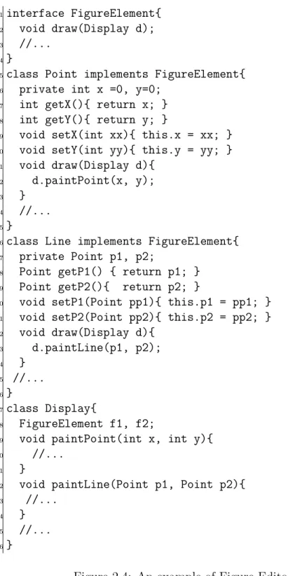
2.4 An example of Figure Editor system(initial version) . . . 14
2.5 DisplayUpdating Aspect . . . 15
2.6 An evolved Figure Editor System(second version) . . . 16
2.7 Accidental capture problem . . . 17
2.8 Accidental misses problem . . . 17
2.9 Fragile Pointcut Problem. . . 17
2.10 An example of Josh . . . 18
2.11 An example of pointcut in Alpha . . . 19
2.12 An example of annoatation-aware interface and annotator aspects . . . 20
3.1 Overview of our framework . . . 23
3.2 A part of relation maps in figure editor system(2) . . . 26
3.3 An example of XML document . . . 27
3.4 An example of relationship tree from figure editor system . . . 29
3.5 An example of Forward Buid and Backward Build . . . 30
3.6 An example of extract interntion pattern . . . 35
3.7 An example of generalize intention pattern . . . 35
3.8 Simple syntax in Tregex . . . 37
3.9 An example of Tregex Pattern . . . 37
3.10 An example of code generator . . . 38
3.11 Example of code template . . . 38
3.12 Procedure of match join point trees in figure editor system . . . 39
3.13 Match result in figure editor system . . . 40
4.1 An example of senario1 . . . 44
4.2 An example of senario2 . . . 44
4.3 An example of senario3 . . . 45
4.5 An example of senario5 . . . 47
4.6 An example of senario6 . . . 48
4.7 An example of senario7 . . . 48
2.1 Comparison of Related Works . . . 21
3.1 Overview eleven relation maps . . . 25
3.2 Details of relation maps . . . 25
3.3 A part of relation maps in figure editor system(1) . . . 26
4.1 Comparison of robustness of pointcuts, based on original name-based point-cut and analysis-based pointpoint-cut . . . 43
Chapter
1
Introduction
Modern software projects are of large scale, often involving tens of thousands of days of work efforts, and millions of lines of code. Moreover our limited minds cannot possibly consider everything and solve everything at once. Therefore, the software is too complex to design merely in a single view, and it is necessary to separate the different concerns in a large piece of software into smaller, more manageable units. Separation of concerns is one of the key principles in software engineering, and it refers to the ability to separate programs into distinct features. Effective separation of concerns makes a program easier to understand, change and debug[4]. Concerns are used to organize and decompose software into manageable and comprehensible parts[14]. Modularity or modular programming is a way of achieving separation of concerns. Object-oriented programming (OOP)[20] is a way of modularizing common concerns, classes in object-oriented model perform a single specific function. In many case, we find that many parts of our system have code fragments for logging, persistence, debugging, authorization, tracing, exception handling, and other such tasks. As a result, they have to be coordinated with other functional unites and code scattered usually throughout several functional units exist in their concerns. Thus, OOP does not do as a good job in these situations. Aspect-Oriented programming (AOP)[18] fills this void. In contrast with OOP, AOP is a way of modularizing crosscutting concerns. Crosscutting concern is a concern that affects several classes or modules. The modules for the crosscutting concerns are called aspects, aspects encapsulate behaviors that affect multiple classes into reusable modules. AspectJ[17] is the most prevalent and studied in mainstream aspect languages. It is a practical aspect-oriented to Java. AspectJ introduces a new concept, join points, and a few new programming constructs, such as pointcuts and advice. A pointcut is a construct designed to identify and select join points. Advice defines code to be executed when a join point is reached. Pointcuts match join points, which are well defined points in the execution of a program, so it is a key element in aspect-oriented languages.
Using names and wildcards to capture join points over programs is the most basic way to define the pointcuts. As the program evolves, changes in the structure or naming conventions can make advice accidentally execute an unwanted advice or miss execute some required ones. In other words, there is tight coupling between aspect and structure
of base codw. In this case, when the program evolved, as even a small modification to the program, the pointcut itself have to evolve along with the base-code. This problem is called fragile pointcut problem[19]. Hence it is important to define pointcuts in a robust way against program evolution. Robustness means the pointcuts are able to continue to capture the correct set of join points without alters its form in future version of the base-code.
There are many approaches[5, 6, 8, 9, 13, 15, 16, 22, 23, 24, 25] that attempt to overcome pointcuts’ fragility. These approaches propose several new pointcut language constructs to improve pointcuts’ expressiveness. There is, however, no automatic way to translate name-based pointcuts into robust ones, and hence programmers have to rewrite the existing pointcuts manually. Unfortunately, this is often difficult because new constructs are very different from the original languages. For example [21] uses a logic programmig language for the specification of pointcuts, it is very different from the name-based pointcuts.
This dissertation reports our work on develop a framework to translate name-based pointcuts into analysis-based pointcuts automatically. Analysis-based pointcut is defined by using static program analysis. There are three significant components in our frame-work, namely, relation analyzer, pattern generator and code generator. Given base-code aspects, it first analyzes the program to extract relation maps that represent relationships among fields, methods, classes and interfaces. Then these relation maps are used by pat-tern generator to build relationship trees which correspond to the given pointcut. Next extract intention pattern from the relationship trees for each pointcut to be translated. Finally, the code generator generates analysis-based pointcuts by using the pattern. In addition we recommend programmer use stable interfaces/names to define their target relevant to particular concern, for it can strength our intention pattern, and increase the accuracy of capture correct set of join points. We implement the framework for AspectJ in Java, and show that the generated analysis-based pointcuts are more robust than their name-based counterparts under various program changes, but still fragile under compli-cate changes, through a case study.
The outline of this paper is organized as follows: Chapter 2 contains a background on the field of Crosscutting concerns, oriented programming and several Aspect-oriented programming languages. Together with analysis-based pointcut which applied in our approach, and some other researches related to the approach of overcome fragile pointcut problem are compared and analyzed in this chapter. Chapter 3 illustrate our framework, and explain how can it alleviate the fragility. Chapter 4 illustrates a case study to evaluate robustness of our approach. Chapter 5 draws the overall conclusion of this research and our plans for future work.
Chapter
2
Setting the Scene
In this chapter, we present background for better understanding this dissertation. Section 2.1 introduces the research background, which covers work in different research domains that our dissertation draw on, including crosscutting concerns, aspect-oriented programming, AspectJ and other AOP languages and fragile pointcut program. Sec-tion 2.2 presents Analysis-based Pointcut[6] and related works. Analysis-based pointcut is one of the approaches to overcome the fragility. A piece of code as an example is also demonstrated in this section. By comparing these approaches, we observe a gap between traditional pointcut language and a new robust pointcut language, and then propose our approach that attempt to generate analysis-based pointcuts instead of traditional name-based pointcuts automatically to fill the gap.
2.1
Research Background
2.1.1
Crosscutting concerns
Object-Oriented Programming (OOP)[20] is the most popular programming paradigm today. The evolution from machine level language to OOP reflects that readability and reusability in designing software are more and more significant. Object-oriented program-ing language is a way of modularizprogram-ing common concerns. Classes in object-oriented model perform a single specific function, however, not all concerns can be encapsulated prop-erly in a functional decomposition, and these classes often share common code fragments. For example, tracing and logging are concerns that have common code fragment that are usually distinct from the functional units. As a result, they have to be coordinated with other functional units and code scattered usually throughout several functional units exist in their concerns. Therefore, Object-oriented programming does not do as a good job in these situations. We call these concerns as crosscutting concerns. Crosscutting concerns are computational units of a program that provide similar functionalities, however cannot be abstracted into a standalone module because of the limitations of the programming language. Crosscutting concerns make the code unclean and unmodularized. Suppose
we change in the crosscutting concerns, meanwhile, we have to change code in several different places. Therefore it leads to code scattering and tangling.
Figure 2.1: Example of crosscutting concerns in figure editor system.
Figure 2.2: Implementtion of crosscutting concerns in figure editor system without AOP
EXAMPLE 2.1. A simplicity of crosscutting concerns example is shown in Figure 2.1. The figure shows the classes used in classic figure editor system[17]. FigureElement is an interface, and it can be either Point or Line. There is also a Display class that draws
Figure on the screen. A Point includes x and y coordinates. A Line is defined as two points p1 and p2. Methods setX and setY of the Point involve two distinct actions. One is updating coordinates in their target object, the other is triggering the redrawing of the display. Updating coordinates x or y of the objet Point is clearly corresponds to methods setX and setY, respectively. Similarly, methods setP1 and setP2 of the Line involve the same actions, Updating p1 or p2 of object Line is clearly correspond to the methods setP1 and setP2, respectively. However, the concern of updating the display has to be handled after execution of setX, setY, setP1 or setP2. Therefore, the display updating concern crosscuts four methods within two classes, and this concern has to be implemented in several classes. The code of example is shown in Figure 2.2. In this case, we add two methods update in both class Point and class Line. Assume that if there are several classes inherit from FigureElement, and we need to redraw the display after modify the value of visual properties in these classes. We have to add the new code in several classes. Fortunately Aspect-Oriented Programming fills this void.
2.1.2
Aspect-Oriented Programming
Aspect-Oriented Programming (AOP)[18] is proposed for improving separation of con-cerns in software. Aspect-Oriented Programming allows the architect to address future potential requirements without breaking the core system architectures, and to spend less time on crosscutting concerns during the initial design phase, since they can be woven into the system as they are required without compromising the original design.
Aspect-oriented programming provides a solution to the crosscutting problem by sup-porting the modularization of crosscutting concerns in a novel construct called aspect. An aspect like a special class with functions that do not need to be directly referenced in another class in order to invoked. Programmer can localize the crosscutting concerns in the system from the core modules, class, and remove scattering and tangling problems from the program. AOP has following definitions: a join point is a point in the code or in the execution of a program at which concern crosscut the application. Generally, there are several join points for each concern. Join points can be considered as hooks within a program where the other parts of program can be conditionally attached and executed.
Join points are classified into two categories: dynamic join points and static join points. Dynamic join points are classified into call join points, execution join points, and field access join points[10]. Execution join points include method execution, initializer exe-cution, constructor exeexe-cution, static initializer exeexe-cution, handler exeexe-cution, and object initialization. Call join points include method call, constructor call, and object preinitial-ization. Field access join points include field references and field assignments. Static join points correspond with types to which new elements can be added.
A pointcut is that point of execution in an application where crosscutting concern needs to be applied. The expression of a pointcut is the pointcut descriptor. Pointcuts capture join points.
Advice is an additional piece of code that a programmer attempt to apply to an existing programming. The body of advice like a method, and contains the logic to be executed at each of the join points in a pointcut. Advice supports before, after, and around advice.
Figure 2.3: Implement of crosscutting concerns in figure editor system with AOP. A before advice executed before a join point. An after advice executes after a join point. Around advice may replace the join point and execute instead of it. In addition there are two special situations, after returning and after throwing,
An aspect is a combination of a piece of code of pointcuts and advice. An aspect can also be more generally defined as a unit that encapsulates a crosscutting concern. The counterparts of aspects are components or base code, which are the functional units of code that only contain base actions, and aspect-oriented statements are not included. Components are units of code when written using functional, procedural or object-oriented languages.
EXAMPLE 2.2. Figure 2.3 shows an example of implement of figure editor system by using AOP techniques. The updating display is implemented in an aspect. A pointcut descriptor in this aspect express the points in the execution flow after returning from methods setX, setY, setP1 or setP2, and the piece of advice associated with this pointcut then repaint the screen. By using aspect-oriented programming technique, we do not have to add new code in several classes.
2.1.3
Aspect-Oriented Programming Languages
There are two types of AOP languages, one is programming language-specific AOP languages, the other is programming language-independent AOP languages[7]. And a lot
of these languages have been developed. For example AspectJ[17] and AspectC++[2] are the programming language-specific AOP languages which have been used widely. Weave.Net[11] is one of the language-independent AOP languages.
Weave.Net
Weave.Net is an independent Aspect-Oriented programming language. It avoids the tight coupling of aspects with components written in a particular programming language[11]. Weave.Net is implemented as a .Net component. The input of Weave.Net is a reference to a component assembly, the reference correspond to an XML document. The XML document contains specification for an aspect.
AspectC++
Aspect C++ is similar to AspectJ. Within AspectC++ designers are defined according to the syntax and semantics of c++. And in AspectC++ the wildcard “%” replaces wildcard “ ∗ ” which in AspectJ.
AspectJ
AspectJ is one of the prevalent and most mature aspect-oriented languages[17]. The AspectJ project started at the Xerox Palo Alto Research Center (PARC), AspectJ now is part of IBM’s open source Eclipse project. AspectJ is an aspect-oriented programming extension of Java that supports crosscutting concerns. It uses regular java statements to write the advice, however it defines a lot of specific constructs for encapsulating aspects and writing pointcuts. For example, some member functions or data that are related in functionality may be part of different classes or nested within different functions, never-theless, the aspect construct can still encapsulate them. A summary of the syntax can be found in Appendix A. AspectJ uses a specific compiler which produces standard bytecode that can be executed on any Java virtual machine.
AspectJ mainly works on the interfaces of the classes. Join Points in AspectJ include method call, constructor call, method call execution, constructor call execution, field get, field set, exception handler execution, class initialization, and object initialization. There are several primitive pointcut designators within AspectJ. Pointcut descriptors are written as logical expressions defining which of these join points need to be picked out. The candidate is based on the name of the objects and methods involved and on their signature, using regular expressions. Pointcut in AspectJ include call, execution, initialization, handler, get, set, this, args, target, cflow, cflowbelow, within, withincode, if, preinitialization and adviceexecution. A call pointcut invokes a method, and a handler pointcut captures the execution of an exception handler in the application. A typical format for pointcut is:
pointcut pointcutN ame([parameters]) : designator(joinpoint)
pointcutName is the name of pointcut, and is used to handle actions. designator decides when join point will match. A pointcut can be combined with three logical operators.
A designator is used to expose the object to advice, or to narrow pointcut selection. Designators include this, target, and args. The designators of cflow and cflowbelow match join points within a given program flow, whereas, within and withincode match classes and methods. If and execution are dynamic designators. Advice in AspectJ supports before, after and around. Before advice can be utilized for checking preconditions and arguments. After advices can be classified into three different advices. The first one is unqualified after advice which runs no matter what the outcome of the join point. The second one is after returning advice which runs only if the join point returned normally. The third one is after throwing advice which executes if the join point ended by throwing an exception. Around advice runs instead of the join point and can invoke the join point using the special proceed syntax.
Aspects in AspectJ can be compared to classes in Java. It is the central unit of AspectJ, as of a class in Java. Pointcuts, advice, declarations and introductions are contained in an aspect. In addition to AspectJ elements, Aspects may contain fields, methods, and nested classes. In this study we implement our approach for AspectJ.
2.1.4
Fragile Pointcut Problem
The fragile pointcut problem[19] is similar to the fragile base class problem in object-oriented programming. Developers cannot determine whether the base class change is safe only by inspecting its methods independently when in OO development. In addition they also need to inspect the methods of subclasses. Translating the problem to aspects, with the purpose of determine whether the base program change is safe, developers have to inspect possible influences in the join point shadows which captured by the particular pointcuts in the program. We briefly explain about two situations of the fragile pointcut problem, namely accidental join point captures and misses.
We use two versions of classic Figure Editor System as an example; one is the initial version of the system with no errors which is shown in Figure 2.4; and the other is the second version, in which pointcuts do not work due to program evolution. Figure 2.6 shows an example of second version system.
1interface FigureElement{
2 void draw(Display d);
3 //...
4}
5class Point implements FigureElement{
6 private int x =0, y=0;
7 int getX(){ return x; }
8 int getY(){ return y; }
9 void setX(int xx){ this.x = xx; }
10 void setY(int yy){ this.y = yy; }
11 void draw(Display d){
12 d.paintPoint(x, y);
13 }
14 //...
15}
16class Line implements FigureElement{
17 private Point p1, p2;
18 Point getP1() { return p1; }
19 Point getP2(){ return p2; }
20 void setP1(Point pp1){ this.p1 = pp1; }
21 void setP2(Point pp2){ this.p2 = pp2; }
22 void draw(Display d){ 23 d.paintLine(p1, p2); 24 } 25 //... 26} 27class Display{ 28 FigureElement f1, f2;
29 void paintPoint(int x, int y){
30 //...
31 }
32 void paintLine(Point p1, Point p2){
33 //...
34 }
35 //...
36}
Figure 2.4: An example of Figure Editor system(initial version)
In the initial version of the system, there are two different figure elements: a point element and a line element. Calls to Point.setX or Point.setY change the position of a point object. Similarly calls to Line.setP1 or Line.setP2 change the position of Line object. Methods draw in class Point and Line are used to implement the operations
1aspect DisplayUpdating{
2 pointcut change(FigureElement felement):
3 execution (* FigureElement+.set* (..)) && target(felement);
4 after(FigureElement felement) returning(): change(felement) {
5 Canvas.update(felement);
6 }
7}
Figure 2.5: DisplayUpdating Aspect
to paint itself, respectively. The display updating concern is implemented in the advice, shown in Figure 2.5. The pointcut change specifies executions of the methods which names starting with text “set” throughout the FigureElement class hierarchy. The advice in lines 4-6 redraws the screen whenever a figure object changes its visual properties.
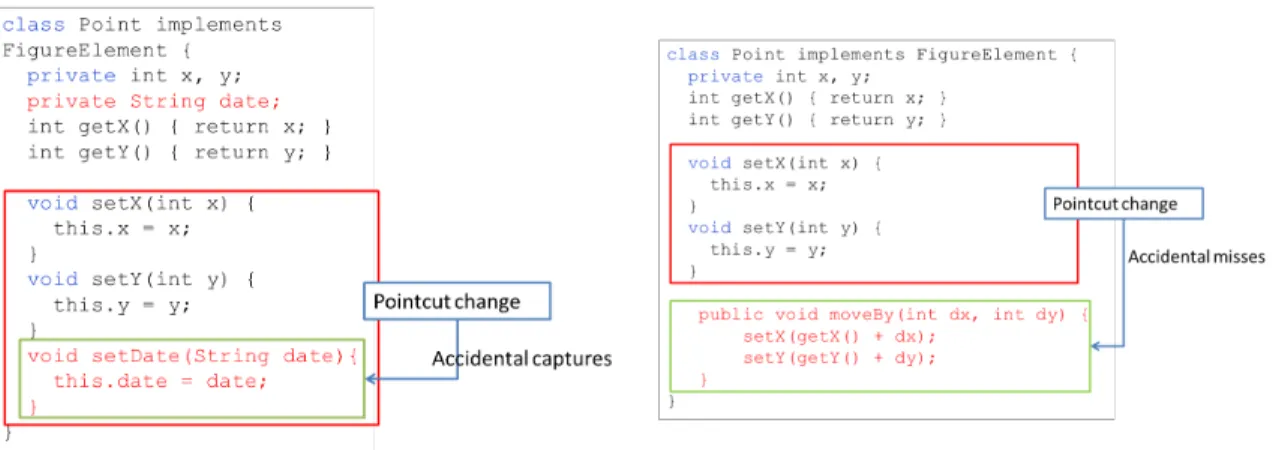
Suppose that the program is changed to add two more operations in class Point in the second version: one is adding a date field to the class Point, the new field represents the last time the figure was saved on persistent store. And adding an associated setDate method to set its value. The other modification is adding a new method moveBy, this method represents move the position of a point from one location to another by add the new value of dx and dy. Figure 2.6 shows the second version of the class Point.
These changes make the advice in Figure 2.5 wrong in two situations. First is shown in Figure 2.7 that when we add a new method setDate into class Point, pointcut change will capture the new method setDate because its name starting with set, when after execute the method setDate, system would repaint the screen, however method setDate does not change any figure element’s visual properties. Second is shown in Figure 2.8 that when we add a new method moveBy into class Point, pointcut change will not capture new method moveBy. Therefore if the Point is moved from one position to other, the screen will not be redrew because its name do not start with set.
The problem occur because the pointcut change does not specify correct join points; it accidentally specifies the execution of the new method setDate in the first case, and misses execution of the method moveBy in the second case. We call the first problem accidental join point capture and the second problem accidental join point miss, respec-tively, in our dissertation. In order to solve these problems, pointcut languages should be improved in order to loosen the coupling between aspect and base code’s structure. Several approaches[5, 6, 8, 9, 13, 15, 16, 22, 23, 24, 25] have been proposed to attack the fragile pointcut problem will be discussed in next section.
2.2
Analysis-based Pointcut and Related Works
This section aims to describe a new pointcut construct language called analysis-based pointcut[6] and analysis of some relevant solutions of fragile pointcut problem. Finally, by comparing several related works, we indicate a gap between traditional name-based
1class Point implements FigureElement{
2 private int x =0, y=0;
3 private sting date;
4 int getX(){ return x; }
5 int getY(){ return y; }
6 void setX(int xx){ this.x = xx; }
7 void setY(int yy){ this.y = yy; }
8 void draw(Display d){
9 d.paintPoint(x, y);
10 }
11 void setDate(string nowdate){
12 this.date = nowdate;
13 }
14 void moveBy(int dx, ind dy)
15 setX(x + dx);
16 setY(y + dy);
17 } 18}
Figure 2.6: An evolved Figure Editor System(second version)
pointcut and new pointcut languages in current aspect-oriented software development. The necessity and significance of filling the gap will be discussed in this section, and indicate our study is the first one that attempt to bridge the gap.
The concept of fragile pointcut problem was proposed by Koppen et al.[19], point-cut is fragile due to the high coupling between aspect and base code’s structure. AspectJ invented abstract aspects in order to reduce coupling. Aspects can contain abstract point-cuts which are defined by inheriting aspects. Therefore, abstract aspect can encapsulate all the advice code and reuse it. However, pointcuts in the concrete aspect still are fragile, even though abstract aspect can reduce coupling.
2.2.1
Analysis-based Pointcut
Analysis-based pontcut[6] is one of the approaches to overcome the fragility. We will utilize some examples to explain analysis-based pointcuts, and how they contribute to more robust than name-based one. Regular expression matching can be considered as a simplest analysis-based pointcut. Pointcus capture join points using regular expression when matching class/method/field names in the join points. This can be considered as an extension to wildcard-based type patterns in AspectJ. The following code of point-cut which proposed by [6] would match any method exepoint-cution whose name consists of lowercase characters only.
Figure 2.7: Accidental capture problem
Figure 2.8: Accidental misses problem Figure 2.9: Fragile Pointcut Problem.
2 execution(.* .*\.[a-z]+(.*));
An analysis-based pointcut which utilized in our approach is defined by using static program analysis, and matched join points that satisfy the match pattern which the pro-gram analysis checks. Ignoring runtime overhead, we can achieve analysis-based pointcuts in existing AOP languages by using the conditional pointcut and introspective reflection as follows:
1aspect DisplayUpdating{
2 pointcut figureChange(FigureElement fe)
3 :(execution (* *.*(..))
4 && if(mayChange(thisJoinPoint)))
5 && target(felement);
6 after(FigureElement fe) returning(): figureChange(fe){
7 Canvas.update(fe);
8 } 9}
The pointcut matches the method execution join points when a figure object changes its visual properties. The method mayChange takes a join point and return “true” if the method changes the visual properties of a figure object.
Compared to an aspect that enumerates all relevant method names or utilize wildcards instead of method names, the use of conditional pointcut clarifies the intention of the programmer. Moreover the aspect is robust against additions of new figure element classes and additions of new methods to existing figure element classes.
2.2.2
Related Works
Expressive pointcut languages
There are several relevant approaches which supporting analysis-based pointcut or sim-ilar to analysis-based pointcut that attempt to overcome fragile pointcut problem.
The Josh[9] and Alpha[21] are new AOP languages. Josh is a language like AspectJ. Josh allows the users to implement a new pointcut designator in Java, and it has its own weaver. However Josh does not support declarative pointcut specifications. Figure 2.10 shows an example of a user-defined designator updater which designed by [9].
1//updater designator:
2updater("FigureElement", "redraw");
4//static method which implement the updater designator:
5static boolean updater(MethodCall mc, String[] args, JoshContext jc){
6 CtClass root = jc.getCtClass(args[0]);
7 String mname = args[1];
8 CtMethod mth = mc.getMethod();
9 //skip if the method is redraw().
10 if(mth.getName().equals(mname))
11 return false;
12 Hashtable fields = enumerateFields(jc, root, mname);
13 update = false;
14 mth.instrument(new ExprEditor(){
15 public void edit(FieldAccess expr){ ... }
16 }):
17 return update;
18}
Figure 2.10: An example of Josh
Method updater returns false if the called method mth is redraw. Otherwise, it in-vokes enumerateField for enumerating the fields that the redraw methods in a subclass of FigureElement read.
Alpha provides rich program information to user defined pointcuts. The Alpha aspect language use a logic programming language for the specification of pointcuts. Figure 2.11 shows an example of enum pointcut in Alpha.
1class DisplayUpdate {
2 Display d;
3 after set(P, x, _ ); set(P, y, _); set (P, ’p1’, _); set(P, ’p2’, _),
4 instanceof(P, ’FigureElement’) {this.d.draw(P);}
5 //...
6}
Figure 2.11: An example of pointcut in Alpha
The enum piontcut (line 3) enumerates all assignments to fields that potentially affect drawing behavior, the fields namely x, y, p1, p2 are in any object P of type FigureElement. This pointcut utilize the names of fields to identify the relevant assignments. Nevertheless, this new pointcut language is difficult to be written by programmer who do not familiar with logic programming language, and its dynamic execution model needs a complex compilation framework to achieve efficient performance.
Although some expressive pointcut languages make pointcut definition much less fragile, they do not solve the problem completely. A pointcut definition still need to refer to specific base program structure or behavior to match its join points. In order to deal with the fragile based on structural dependencies, Kellens et al.[15] propose a novel pointcut construct language so-called model-based pointcuts. These new pointcuts are decoupled from the base program structure, for conceptual model instead. For example, assuming that the conceptual model contains a classification of all figurechange methods in the implementation of the figure editor system. The model-based pointcut that captures all join points to figurechange methods could be defined as:
1pointcut figurechange():
2 classifiedAs(?methSignature, FigurechangeMethods) &&
3 call(?methSignature);
where the expression classifiedAs(?methSignature, FigurechangeMethods) matches all methods that are classified as figurechange methods in the conceptual model of the figure editor system, and the variable ?methSignature is bound to the method signa-ture of such a method. This Pointcut definition explicitly refers to the concept of a figurechange method rather than attempting to capture concept by depending on im-plicit rules about the base system’s implementation structure. Therefore, this pointcut does not need to be changed when the base system is evolved. Obviously, this new point-cut language is more powerful, however, similar to the Alpha, this pointpoint-cut language is also difficult to be written by programmers who do not familiar with new language. Annotation
An alternative solution that has been proposed is to define pointcuts in terms of explicit annotations in the code. Silva et al.[23] propose a solution relies on invasive and non-scattered annotations to solve the fragile pointcut problem. The central components of the proposed solution are annotator aspects that superimpose annotations to the based
code in a non-invasive way. Figure 2.12 shows an example of annotation-aware interface and annotator aspects in this approach.
1//annotation-aware interface associated to the class Point
2class Point{
3 DisplayStateChagne void setX(int);DisplayStateChange void setY(int);
4}
6//annotator aspect
7aspect DisplayStateChange{
8 declare method :public void Point.setX(int) : DisplayStateChange;
9 declare method :public void Point.setY(int) : DisplayStateChange;
10 //...
11}
Figure 2.12: An example of annoatation-aware interface and annotator aspects Line 1-4 implements annotation-aware interface and line 6-11 implements annotator aspect. By using this approach, the following pointcut is decoupled from the base system, but it also requires programmers to annotate correctly all methods that change the state of the display.
1pointcut change() ;
2 execution(void DisplayStateChange *.*(..))
Moreover, this solution is particularly recommended in two situations: when it is pos-sible to correlate annotations, and it is pospos-sible to restrict the scope of an annotation. Integrated Tools and Frameworks
Pointcut rejuvenation[16] and Pointcut-Doctor[25] are integrated tools that assist pro-grammer to write correct pointcuts. Pointcut rejuvenation picks up a lot of suggested join points which are ranked by the value of confidence after program evolved. Pointcut-Doctor is an extension of AJDT tools that helps programmers write correct pointcuts by providing immediate diagnostic feedback. This approach present an algorithms to compute two kinds of information about AspectJ pointcuts: almost matched join point shadows and explanations. The algorithm has two variants, and their algorithm captures join points by changing the names in the pointcut slightly.
Anbalagan et al.[5] propose a framework to generate pointcut mutants with different strengths, and assist developers inspect the pointcut and their join points conveniently. For example, consider the arguments “(int, float, String)”. The mutants formed for this argument will be (int, float, ..), (int, .., String), (.., float, String), (.., float, ..), (int, ..), (.., String), and (..).
However these solutions cannot update original pointcut, and need programmers to discriminate correct join points, then revise original name-based pointcuts manually.
Crosscutting interface (XPIs)
XPIs are explicit, abstract interface that decouple aspects from details of advised code[12]. XPIs define contracts that programmers must observe. On the other hand, aspect developers must rely on the syntactic part of XPIs to implement advices that do not directly reference source code elements. Pointcuts based on XPIs are also more ro-bust, since the base code have to adhere to the defined design rules even after changes. Design rules enforced by XPIs are implemented in AspectJ.
2.2.3
Summary
Solution Type Objective Problem
Josh[9] Expressive
pointcut language
Get robust join points after program evolved
Difficult to write
Alpha[21] Expressive
pointcut language
Get robust join points after program evolved
Difficult to write
Pointcut Mutants[5]
Framework Assist programmer
in-spect the pointcut and their join points con-veniently
Need to modify origi-nal pointcut manually
Annotation Pointcut Language[23]
Annotation Get robust join points after program evolved
Need Programmer to decide whether should be annotated Analysis-based Pointcut[6] Expressive pointcut language
Get robust join points after program evolved
Difficult to write Model-based Pointcut[15] Expressive pointcut language
Get robust join points after program evolved
Difficult to write Pointcut Rejuvenation[16] Integrated tool Assist programmer
write correct
point-cuts after program
evolved
Need to modify origi-nal pointcut manually
Pointcut Doctor[25]
Integrated tool
Assist programmer
write correct
point-cuts after program
evolved
Need to modify origi-nal pointcut manually
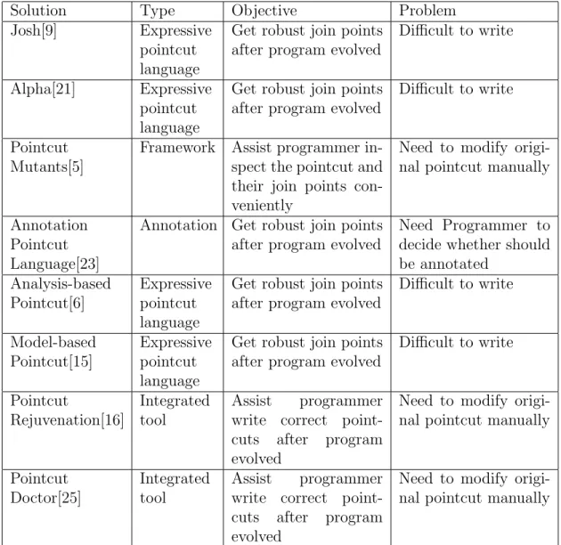
Table 2.1: Comparison of Related Works
To summarize we compare several different solutions on overcome pointcut fragile prob-lem, as shown in Table 2.1. We find that new pointcut construct language which improve
their expressiveness are very different from the original pointcut language, thus, the new robust pointcut languages are difficult to be written by programmers who do not famil-iar with new pointcut languages. In addition integrated tools and framework can only assist programmer to check the correctness of join points in order to revise original point-cuts manually. In consequently, there is a gap between traditional name-based pointpoint-cuts and other new pointcut languages, and no approach can update original pointcuts au-tomatically after program evolves. We propose a framework called Nataly can translate name-based pointcut into analysis-based pointcut automatically in order to bridge the gap.
Chapter
3
Proposed Framework-Nataly
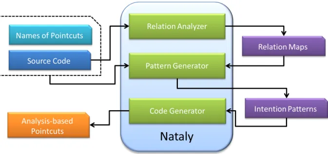
Figure 3.1: Overview of our framework
3.1
Overview of Proposed Framework
This section explains Nataly, a framework for translating name-based pointcuts into analysis-based pointcuts automatically.
Figure 3.1 shows the overview of the framework. It consists of three significant compo-nents, namely relation analyzer, pattern generator and code generator. The framework takes classes, aspects and the names of pointcuts as input. The names are used to iden-tify which pointcuts are to be translated into analysis-based pointcuts. Then the relation analyzer generates eleven relation maps that represent relationships among fields, meth-ods, classes and interfaces. These maps are used by the pattern generator to extract the
intention patterns for each pointcut to be translated. And finally, the code generator generates analysis-based pointcuts by using the information.
3.2
Assumptions
Before introduce the core of our framework, we will indicate some significant assump-tions first. Because our framework presented in this work is under these key assumpassump-tions. • We assume that the initial pointcut which to be transferred is specified correctly. Because the component of pattern generator needs the initial pointcut as an input, and extract intention pattern by using relationship trees which are built correspond to a given pointcut. If the pointcut is not correct, then its counterpart analysis-based pointcut will not capture the correct set of join points. Specifically, we assume that advice is created to materialize the implementation of concern which crosscuts the underlying base code. So the pointcut bound to the advice should quantify over the join points which correspond to this crosscutting concern.
• We assume that aspects are indeed separate from the base code, and advice may only apply to join points associated with classes, interfaces, and other Java types. • Furthermore, we assume that the original source code successfully compiles under
an AspectJ Development Tools (AJDT) compiler.
Lastly, we assume that the pointcut which need to be transferred is not an anonymous one. Because our framework need the name of pointcut and then generates its counterpart, if the pointcut does not have a name, it is difficult to know which pointcut need to be transferred. In the future, we plan to also support pointcut designators as an input in order to support anonymous pointcut transformation.
3.3
Relation Analyzer
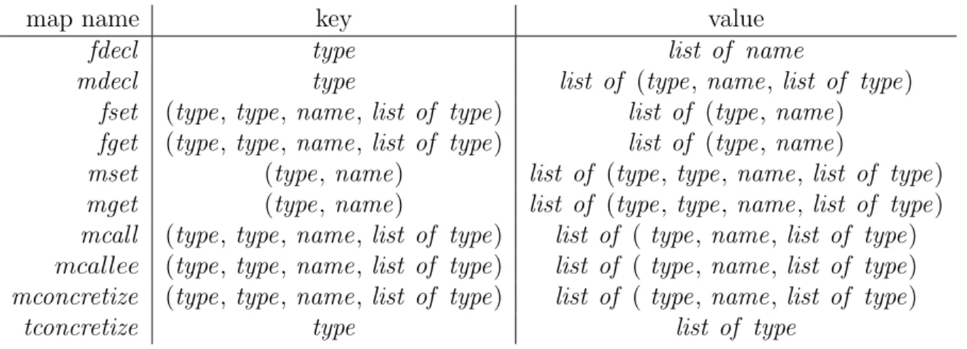
The relation analyzer generates eleven relation maps by analyzing the source code. The relation maps describe the relationship between two program elements. These maps are defined in Table 3.1. type ranges over the names of classes and interfaces, and name ranges over the names of methods and fields. Notice that there are two types of relation maps. One is adjacent relation map which means the relationship between element A and B follow the forward direction. For instance, relation map of mcall between A and B represents that method A calls method B; On the other hand, its counterpart called opposite relation map. The opposite relation map often describes the same relationship between A and B, but in opposite direction. For instance, relation map of mcallee between A and B represents that method A is called by method B. If we analyze adjacent relation map, we call this analysis as a forward analysis. Otherwise, if we analyze opposite relation map, we call this analysis as a backward analysis. The details of each relation map are described in Table 3.2.
map name key value
fdecl type list of name
mdecl type list of (type, name, list of type)
fset (type, type, name, list of type) list of (type, name)
fget (type, type, name, list of type) list of (type, name)
mset (type, name) list of (type, type, name, list of type)
mget (type, name) list of (type, type, name, list of type)
mcall (type, type, name, list of type) list of ( type, name, list of type) mcallee (type, type, name, list of type) list of ( type, name, list of type) mconcretize (type, type, name, list of type) list of ( type, name, list of type)
tconcretize type list of type
Table 3.1: Overview eleven relation maps
map name description
fdecl represents a set of fields declared by a class.
Its key is a class name, and the value is a list of field names. mdecl represents a set of methods declared by either a class or an interface.
Its key is a class name, and the value is a list of triples (type, name, list of type) that identifies a method.
cdecl represents a set of classes declared by a class.
Its key is a class name, and the value is a list of class names.
fset represents a set fields that are to be updated within a method.
Its key, (type, type, name, list of type), identifies a method; type1 is the return type; type2 is the class name that declares the method; name is the method name; and list of types is the argument tpes. The value list of (type, name) is the set of undered fields, where type is a class that declares the field and name is its name.
fget represents a set of fields whose values gotten within a method.
Its key is a method, and its value is a set of accessed fields.
mset represents a set of methods that updates the value of field.
Its key is an updated filed, and its value identifies a set of methods.
mget represents a set of methods that gets the value of a field.
Its key is an accessed field, and its value identifies a set of methods.
mcall represents a set of methods called within a method.
Its key identifies a method, and its value identifies a set of called methods.
mcallee represents a set of methods that calls a method
Its key identifies a called method, and its value identifies a set of methods.
mconcretize represents a method that overrides/implements a list of method. Its key identifies a method, and its value identifies a set of methods. tconcretize represents a class extended by a class, or set of interface extended
by an interface/implement by a class.
Its key is a class/Interface name, and the value is a list of class and
The fdecl , mdecl , cdecl , fset , fget and mcall are adjacent relation maps. The rest relation maps of mcallee, mset , mget , mconcretize and tconcretize are opposite relation maps.
Analysis ralation map map name key value
Forward Analysis
Point −−−→ moveBymdecl mdecl Point moveBy
moveBy −−−→ setXmcall mcall moveBy setX
setX −−→ xf set fset setX x
moveBy −−−→ setYmcall mcall moveBy setY
setY −−→ xf set fset setY y
Backward Analysis
x −mget−−→ Point.draw mget x Point.draw
Point.draw −−−−−−−→mconcretize FigureElement.draw
mconcretize Point.draw
Figure-Element.draw
y −mget−−→ Point.draw mget y Point.draw
Table 3.3: A part of relation maps in figure editor system(1)
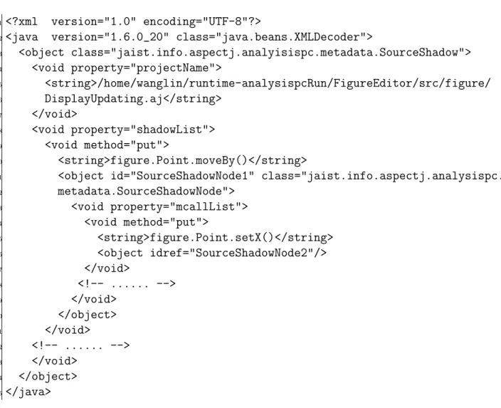
EXAMPLE 3.1. Table 3.3 and Figure 3.2 show a part of relation maps within figure editor system in different views. By using forward analysis, we can find that class Point declares method moveBy, and method moveBy calls method setX, and method setX sets the value of field x. Method moveBy also calls another method setY, and method setY sets the value of field y. On the other hand, by using backward analysis, we can see that the value of filed x is gotten by method Point.draw, and the method Point.draw implements the method FigureElement.draw in an interface. The value of field y is gotten by method Point.draw, and the method Point.draw implements the method FigureElement.draw in an interface. In addition relation maps will be persisted as an Extensible Markup Language (XML). Figure 3.3 shows the example of a mcall relation map between method moveBy and method setX in an XML document.
1<?xml version="1.0" encoding="UTF-8"?>
2<java version="1.6.0_20" class="java.beans.XMLDecoder">
3 <object class="jaist.info.aspectj.analyisispc.metadata.SourceShadow"> 4 <void property="projectName"> 5 <string>/home/wanglin/runtime-analysispcRun/FigureEditor/src/figure/ 6 DisplayUpdating.aj</string> 7 </void> 8 <void property="shadowList"> 9 <void method="put"> 10 <string>figure.Point.moveBy()</string>
11 <object id="SourceShadowNode1" class="jaist.info.aspectj.analysispc.
12 metadata.SourceShadowNode"> 13 <void property="mcallList"> 14 <void method="put"> 15 <string>figure.Point.setX()</string> 16 <object idref="SourceShadowNode2"/> 17 </void> 18 <!-- ... --> 19 </void> 20 </object> 21 </void> 22 <!-- ... --> 23 </void> 24 </object> 25</java>
3.4
Pattern Generator
This section aims to explain the component of pattern generator. The pattern genera-tor generates intention patterns using the relation maps created by the relation analyzer. An intention pattern is relevant to a given pointcut, and intuitively represents the rela-tionships among elements associated with matched join point shadows. And the primary pattern is first proposed by point rejuvenation[16]. We utilize these patterns to express the essence of the programmer’s intentions with regard to the input pointcut. There are three phases in pattern generator: build relationship trees, extract intention pattern and persist pattern format to Tregex pattern format[3].
3.4.1
Build Relationship Trees
In this section we present how to build the relationship trees. First, we obtain join point shadows correspond to a given pointcut by the support of AJDT compiler ( http:// eclipse.org/ajdt ). Second, we utilize the join point shadows to find out the associated java elements from the relation maps. Third, we utilize java elements which associated with join point shadows as a root to build the tree by using relation maps. When build the trees there are four principles of rules need to be complied with:
• When we forward build the tree, if the last vertex is a method, then we stop to build this branch, and use current method as a target in this branch.
• When we forward build the tree, if the last vertex is a field, we save this vertex as a temporary target, and then continue to backward build the tree by using opposite relation maps.
• When we backward build the tree, if the current vertex is an abstract method within an abstract class or an interface, then we stop to build this branch, and use current abstract method as target in this branch.
• When we backward build the tree, if we cannot reach an abstract method in current branch, then we stop to build this branch, and use the temporary target as a genuine target in this branch.
The vertex on the tree is represented by Vpc or Vnpc; the edge of the tree is represented
by R. The tree likes a log that records the behavior of the Vpc. Vpcis an element associated
with join point shadows in the program matched by a given pointcut; Vpc will become
join point shadows ultimately. Vnpc is an element in the program which isn’t matched by
the given pointcut. Similarly, R represents a relationship between two elements in the program. The last R along with target represent the objective of the behavior of the Vpc.
EXAMPLE 3.2. Figure 3.4 illustrate how to build a relationship tree from figure editor system. In order to build the tree we need to utilize relation maps which generated by relation generator, and the example of relation maps have been described in Figure 3.3. In figure editor system, we have a method execution pointcut called change, First, we
Figure 3.4: An example of relationship tree from figure editor system
capture four join point shadows, method setX, method setY, method setP1 and method setP2 which matched by the pointcut change by the support of AJDT compiler. We use method setX as a root to illustrate how to build the tree in this example. By complied with the principles of rules which mentioned before, from method setX we find that there is a relationship called fset between method setX and field x in class Point. Thus, we add the vertex x into the tree. Next, we find that vertex x is a field and it is the last vertex in this tree, therefore follow the second principle, we save vertex x as a temporary target, and continue to backward build the tree by using opposite relation maps. Next we find that there is a relationship called mget between field x and method Point.draw, and method Point.draw maps to the method FigureElement.draw called mconcretize. thus, FigureElement.draw is an abstract method, according to the third principle, we stop build the tree, and set the vertex FigureElement.draw as a target. Now, the tree has been built completely. setX corresponds to Vpc, x and Point.draw correspond to Vnpc,
and labels fset , mget and mconcretize denote relationship R.
Figure 3.5 shows two different build ways in this example. As we have mentioned before, we have two types of relation maps, namely adjacent relation map and opposite relation map, respectively. If we use adjacent relation maps to build the tree, then we call this way as forward build. On the other hand, if we use opposite relation maps to build the tree, then we call this way as backward build. In the Figure 3.5, we build the tree from vertex setX to vertex x by the forward way, from vertex x to vertex FigureElement.draw, the tree is built by the backward way.
Figure 3.5: An example of Forward Buid and Backward Build
3.4.2
Extract Intention Pattern
Intention Pattern
An intention pattern is relevant to a given pointcut, and intuitively represents the relationships among elements associated with matched shadows. The purpose of these patterns is to approximate the essence of the programmer’s intentions behind the original pointcut. As we have mentioned before, the relationship tree represents the behavior of the associated join point shadows matched by a given pointcut. The intention pattern is generated from several relationship trees through analyze their properties, including keeping common properties, disjunctioning different objective and generalizing insignifi-cant vertex (Vnpc).
In addition to four elements in relationship tree, there are three other elements in our intention pattern, namely W ildcardpc, W ildcardnpc and W ildcardR. Wildcards are used
to match patterns with other trees in order to obtain possible join point shadows. Pattern Extraction
We have introduced in section 3.4.1, there are four elements in our relationship trees, namely Vpc, Vnpc, R and target. During pattern extraction phase, Vpc will be replaced
by W ildcardpc, and Vnpc may be replaced by W ildcardnpc within an intention pattern.
Similarly, R may be replaced by W ildcardR. For example, ?* R1
−→ ? −→ ?R2 −→ target is aR relationship tree, where notation ?* denotes W ildcardpc, notation ? denotes W ildcardnpc.
Algorithm 1 defines a function that can extract pattern from the relationship trees. Initializes a set P to be an empty set of patterns to be returned at line 1. The algorithm then separate the relationship trees into several groups according to the same target by function ClassifyTree. Π is a list that contains several sets of trees, each set contains a group of trees that have the same target. Notice that each tree may be copy to many groups due to the multi-target. For example, if a tree has three branches, and each
branches has three different targets. And there are three groups correspond to each
target. Then the tree will be copy to three groups. Function CutUnusefulBranch is used to remove branches which target do not exist in. After cut the branches by function CutUnusefulBranch, each tree only has one branch that contains the vertex of target.
In other words, after cut the unuseful branches, π0 represents a set of path that has the same target. ExtractV P attern is used to abstract vertexes from the tree. Algorithm 2 defines ExtractVPattern function. It receives one parameter, namely π0 which represents a set of paths which has the same target. To do so, we first initialize a set P and a pattern α to be an empty value. Next, algorithm checks each vertex in the tree, if the vertex is Vpc, then algorithm adds the vertex and its followed relation R into the pattern
α. And then continue to check the vertex in sequence. If all the trees do not contains this vertex, algorithm uses W ildcardnpc replace the vertex of Vnpc, and adds a pair of
new vertex and its followed relation R into the pattern α. Otherwise, algorithm keeps this vertex and adds it and its followed relation R into the pattern α. After abstract every vertex, algorithm disjunctions of each pattern α to the set P. Finally, the function ExtractV P attern retruns set P. On the other hand, function ExtractRPattern is used to abstract relationship from the tree. Algorithm 3 defines ExtractRP attern function. It receives one parameter, namely π0 which represents a pattern, in fact it is a set of paths that consist of W ildcardpc, relationship R, Vpc/W ildcardnpc, and target. To do so,
we initialize a set P and a pattern β to be an empty value. Next algorithm checks if relationship R satisfied Condition 1 or Condition 2, then it replaces relationship R by W ildcardR. Otherwise, it keeps relationship R in the pattern.
CONDITION 1. Adjacent Relationship Abstraction Conditions: to a given adjacent relationship r and its index of path i.
• All the vertexes within all the different trees must same in the index of i+1. • At least one tree does not contain relationship r in the index of i.
CONDITION 2. Opposite Relationship Abstraction Conditions: to a given opposite relationship r and its index of path i.
• All the vertexes within all the different trees must same in the index of i. • At least one tree does not contain relationship r in the index of i.
Other process is similar to the function ExtractV P attern. Next we use function Com-binePattern to combine the repeated patterns and remove redundant patterns. Finally, we generalize the pattern by using function GeneralizeP attern. Function GeneralizeP attern receives one parameter, namely P, which represents a pattern. In order to generalize the pattern, algorithm adds a general element between two adjacent vertexes in pattern. A general element consists of arbitrarily number of W ildcardnpc and W ildcardR. In other
words, the hierarchical relationship between two original vertexes is changed from parent to ancestor.
Algorithm 1 Extract Pattern
1: function ExtractPattern(T) //T is the set of relationship trees which
generated in the first phase
2: P ← ∅ //the set of patterns to be returned, initially empty
3: P0 ← ∅
4: π0 ← ∅
5: Π0 ← ∅
6: Π ← Classif yT ree(T )
7: //Π is a list of sets of trees which classified by their target
8: for all π ∈ Π do //each π is a set of tree which has the same target
9: π0 ← CutU nusef ulBranch(π)
10: // π0 is a set of paths which has the same target
11: Π0 ← ExtractV P attern(π0) //Replace some vertexes by wildcard
12: P0 ← P0∪ Π0
13: end for
14: for all π0 ∈ P0 do
15: Π0 ← ExtractRP attern(π0) //Replace relation R by wildcard
R 16: P ← P ∪ Π0 17: end for 18: P ← CombineP attern(P ) 19: P ← GeneralizeP attern(P ) 20: return P 21: end function
Algorithm 2 Extract Vertex Pattern 1: function ExtractVPattern(π0) 2: P ← ∅ 3: α ← ∅ 4: for all t ∈ π0 do 5: for all v ∈ t do 6: r ← GetRByV ertex(v, t) 7: if IsVPC(v) then 8: α ← α + (?∗)r
9: else if IsTarget(v) then
10: α ← α + (v)r
11: else if AllTContainsV(v, t) then
12: α ← α + (v)r 13: else 14: α ← α + (?)r 15: end if 16: end for 17: P ← P ∪ α 18: end for 19: return P 20: end function
Algorithm 3 Extract Relation Pattern 1: function ExtractRPattern(π0) 2: P ← ∅ 3: β ← ∅ 4: for all t ∈ π0 do 5: v ← GetV ertexByIndex(i, t) 6: β ← β + (v) 7: n ← getM axLength(t) 8: for i ← 1, n − 1 do 9: r ← GetRelation(i, t) 10: v ← GetV ertexByIndex(i + 1, t) 11: if AllTContainsR(r, i, π0) then 12: β ← β + (v)r 13: else 14: if IsAdjacentR(r) then
15: if IsAllV ertexSame(v, i + 1, π0) then
16: β ← β + (v)? 17: else 18: β ← β + (v)r 19: end if 20: else 21: v0 ← GetV ertexByIndex(i, t)
22: if IsAllV ertexSame(v0, i, π0) then
23: β ← β + (v)? 24: else 25: β ← β + (v)r 26: end if 27: end if 28: end if 29: end for 30: P ← P ∪ β 31: end for 32: return P 33: end function
Figure 3.6: An example of extract interntion pattern
Figure 3.7: An example of generalize intention pattern
in figure editor system. In this example, all the trees have a same target, so we only have one group of pattern. And every tree has only one branch, so we do not need to cut the unuseful branches. Next, we use W ildcardpc replace vertex setX, setY, setP1
and setP2 in four trees. After that, we get four temporary patterns: ?∗ −−→ xf set −mget−−→ P.draw −−−−−−−→ F.draw; ?∗mconcretiize −−→ yf set −mget−−→ P.draw −−−−−−−→ F.draw; ?∗mconcretiize −−→ p1f set −mget−−→ L.draw −−−−−−−→ F.draw; ?∗mconcretiize −−→ p2f set −mget−−→ L.draw −−−−−−−→ F.draw. Next, themconcretiize other vertex will be abstracted by W ildcardnpc. Because vertex x is not exist in other
trees, vertex x is replaced by W ildcardnpc. Similarly vertex y, p1 and p2 are also not
exist in other trees, and they are also replaced by W ildcardnpc. For the same reason,
vertexes of P.draw and L.draw are replaced by W ildcardnpc. Now, we get four
tempo-rary patterns: ?∗ −−→?f set −mget−−→? −−−−−−−→ F.draw; ?∗mconcretiize −−→?f set −mget−−→? −−−−−−−→ F.draw;mconcretiize ?∗ −−→?f set −mget−−→? −−−−−−−→ F.draw; ?∗mconcretiize −−→?f set −mget−−→? −−−−−−−→ F.draw. We find thatmconcretiize these four patterns are identical with each other. In addition, notice that the relation-ship R does not satisfies our conditions, because of the identical name. Therefore, we keep original relationship R in the pattern. Finally, by combined the repeated pattern and removed redundant pattern we get the final pattern: ?∗−−→?f set −mget−−→?−−−−−−−→ F.draw.mconcretiize
Figure 3.7 explains the generalization of pattern in figure editor system. In this example, between first vertex and second vertex, we add a general element, namely, < ∗, f set > , Notation < ∗, f set > represents that there are arbitrarily number of W ildcardnpc and
W ildcardR between these two vertexes, and last relationship is restricted to fset . For
example, it is equivalent to: ?∗ −→?? −→? · · ·? −−→?f set −mget−−→? −−−−−−−→ F.draw . Similary,mconcretize generalize other parts of the pattern, Finally, we obtain the intent pattern: ?∗ −−−−−→<∗,f set> ?−−−−−→?<∗,mget> −−−−−−−−−−→ F.draw.<∗,mconcretiize>
3.4.3
Tregex Pattern Format
We integrate Tregex (http://nlp.stanford.edu/software/tregex.shtml) which sup-ported by Stanford Natural Language Processing Group as a tree match engine to help us match the trees by using the intention pattern. Tregex is a utility for matching patterns in trees, based on tree relationships and regular expression matches on nodes. Tregex needs a specific format of the pattern. So we need to persist our intention pattern to Tregex Pattern format.
The basic units of Tregex are Node Descriptions. Descriptions match node labels of a tree, such as a Literal string “NP”, Symbol “|” separates disjunction of literal strings, like NP|PP|VP. Tregrex also support regular expression. Notice that wildcard symbol “ ” (two underscores) are used to match any node. Moreover, descriptions can be negated with “!”. Figure 3.8 shows a few symbols and its meanings.
Figure 3.8: Simple syntax in Tregex
Figure 3.9: An example of Tregex Pattern
EXAMPLE 3.4. Figure 3.9 shows an example of Tregex Pattern in figure editor system. It describes two different forms of one pattern.
3.5
Code generator
Code generator generates an analysis-based pointcut for each specified pointcut auto-matically.
Figure 3.10: An example of code generator
3.5.1
Generate Analysis-based Pointcut Automatically
Code generator is done by filling string templates. Figure 3.10 shows an example of code which generated by this component automatically. The pattern object represents the intention pattern of a certain pointcut. The pointcut matches the method execution join points when a figure object changes its visual properties. The method mayChange takes a join point and return true if the method changes the visual properties of a figure object. The methods getPattern, getRelationTree are defined in our library. StringTemplate( http://www.stringtemplate.org/ ) is a java template engine for generating source code, web pages, emails, or any other formatted text output. In order to generate the analysis-based pointcut, we need to define a code-template. Figure 3.11 shows an example of a code template in figure editor system.
1$\n$
2 pointcut $pt_name$($args; separator=","$)$\n$ : $statement$ $\n$
3 && !within($class$) $\n$
4 && if($condition_name$(thisPointPoint)) $\n$;
6 static boolean $condition_name$(JoinPoint jp){
7 String jp_name = jp.getSignature().toString().replaceAll(" ","");
8 return getRelationTree(jp).match(p);
9 } $\n$
Figure 3.12: Procedure of match join point trees in figure editor system
3.5.2
Match join point trees by pattern
This section explains how to match join point trees by intention pattern. To a given join point shadow, we can obtain its corresponding element in relation maps, use these elements as roots to generate relationship trees from the relation maps. The root in each trees is the given join point shadow. After that we use intention pattern to match the relationship tree. Figure 3.12 shows the procedure of how to match join point trees by pattern. In this example, we need to explain that method moveBy whether can be matched by analysis-based pointcut is equivalent to whether it can be matched by the pattern. moveBy tree is generated by using join point shadows from relation maps on the left of the Figure 3.12. TregexPattern is extracted by the pattern generator before which we have explained in section 3.4.2. We use a Tregex tool to verify whether moveBy tree can be matched by the intention pattern. Figure 3.13 shows the result of the experiment. In this figure, we can see that “1 unique trees found with 6 total matches”. In fact this tool checks sub-trees, so there are six sub-trees are matched by the pattern. However, in our framework, we merely use Tregex API to get a boolean value in order to verify whether the join point tree can be matched by an intention pattern.
Figure 3.13: Match result in figure editor system
3.6
Stable interfaces/names
We presume that stable interfaces/names are used to define the target. For instance, in the example of figure editor system, the method FigureElement.draw is one of the most important method and changing the name of this method is very unlikey. Because method FigureElement.draw is defined in an abstract interface. So when add some new functions to the original system, we rarely change the method in an interface. If we modify abstract method, all the method in sub-classes should be changed. Therefore, changing the name of this method is unlikely. On the other hand, we often use some other Java APIs or frameworks(e.g., Java persistence framework) in our software to implement some specific functions. The methods in these APIs or frameworks are rarely to change, thus we presume that the names of these methods are stable names. Consequently, we recommend programmer using Java stable names/interfaces to define their target in order to make