The Sliding Mode Control of Bridge Vibration under a Moving Vehicle
by
Toshiaki KAGA, Takatoshi OKABAYASHI Tadao NAKAMURA
The linear quadratic regulator theory is applied to the active control of bridge vibration conduced by traffic loads. As the bride-vehicle system is the time varying system, the stationary LQR control is not op- timal control for the bridge vibration. In bridge vibration under traffic loads, uncertain factors such as the vehicle number, the types of vehicle moving speed etc. exist, therefore, the control theory has to be con- sidered these factors. Then, for these uncertainties, the robust control is expected. This study concerned with the control of bridge vibration under a moving vehicle using by the sliding mode theory that has robustness for the time-varying system. The effectiveness of sliding mode control theory is discussed by the numerical simulations for active and hybrid control of bridge vibration.
1. INTRODUCTION
In recent years, it becomes a problem that traffic vibration obstacle is caused in surrounding areas of a urban highways under traffic loads. This problem is caused as the follows. Vibration of bridge girders is resonated under moving vehicles which is excited at random road surface roughness. This vibration transmit to the bridge pier and the ground, and resonate buildings. This vibration gives a feeling of unpleasantness to inhabitants. As one of measures to this problem, passive control has been applied to the bridge vibration by using TMD. Because the dynamic characteristics of the bridge-vehicle system vary with time, this system is called time-varying system. So ac- tive controP) adding the control force directly to the bridge girder is subjected to attention, and further- more an application of hybrid controF) which has ef- fectiveness of passive control is suggested.
In bridge vibration under traffic loads, natural fre- quencies of the bridge change with time. The system becomes time-varying system3) changing of the pa- Received on April, 1998
*Graduate School of Marine Science and Engineering
*
*
Department of Civil Engineering***Department of Faculty of Environmental Studies
rameter. Optimal regulator theory has been applied to bridge vibration under moving vehicle. This theory should be applied to stationary system that has a cons- tant parameters. In this study, sliding mode theo-
ry3)4) 5) that has robustness for the time-varying
system is applied to active and hybrid control of bridge vibration under traffic loads.
Sliding mode theory is a new control~method that designs switching line on phase plane and slides system response over this line. Because the switching of control force has become easy by remarkable development such as a personal computer and DSp6) in recent years, sliding mode theory attracts attention in the field of control electrical engineering. Sliding mode theory has robustness in nonlinear system, changes of the parameter value, time-varying system, unknown parameter system and unknown external force. Therefore, it is applied to buildings, elastic rotors, brakes systems,vehicles and universe robots etc.4) 7) 8) 9) 10) 11) 12) 13). In this study, sliding mode theory having such characteristics is applied to the
bridge vibration that is the time-varying system, and the effectiveness are discussed by the numerical simulations.
displacement of road roughness, vis the speed of the vehicle, u(t) is control force.
The bridge is considered up to 3th order vibration, and the state variables is introduced as
Xa(to) =xao
WhereAa(f) is the system matrix of bridge-vehicle system, Da(f) is the external force matrix which define the locations of excitation, andBa(t) is the con- trol force matrix which define the locations of control When the displacement of road roughness observed from the vehicle is expressed in ret) and the time derivative ofr(t) is expressed inr(t),the variable vec- tor of road roughness can be defined as
ret) = [ret) ret)JT. (6)
Using by these Eqs. (4) (5) (6), Eqs. (2) (3) can be described with the state equation that is
x
a(t) =Aa(t)Xa(t)+
Da(t) r(f)+
Ba(t)u(t)2. CONTROL METHOD OF BRIDGE-VEHI-
CLE SYSTEM VIBRATION AND MODEL- ING OF ROAD ROUGHNESS
(1) Active control
Active control of bridge-vehicle system vibration is shown as Fig.l. A single vehicle modeled as one- degree of freedom by the spring-mass system moves with constant speed von the simple span bridge that contains road roughness. Active control is done by an actuator fixed atx=bpoint of the bridge. When a con- trol forceu(t) is acted and bridge vibration modes are considered up to n-th order, the equations of displace- ment response in x point of the bridge, the normal coordinate of bridge and the vehicle are given as follows:
q(t) = [q1(t) q2(t) q3(t)
JT
xa(t)= [q(t)T q(t)T Z(t) Z(t)JT
(4) (5)
n
y(x, t) = ~ (/Jk(x)qk(t),
k=1
iik(t)
+
2hk Wk (b(t) +Wjqk(t) =-Pkz (!>k(vt)i(t) +¢Jk(b)u(t)/mk (2) (k= I, ''', n)'
"i.(t)+ 2howo{2:(t)-y(vt, t)-ret)}
(3) +WHz(t)-y(vt, t)-ret)} = 0 Where y(x, t) is the displacement of the bridge at x point,¢Jk(X) is thekth vibration mode of bridge,qk(t)
is the normal coordinate, z(t) is the vertical displace- ment of the vehicle, Wk, Wo, hkandhoare the natural circular frequencies and the damping constants of the bridge and the vehicle respectively, Pkz is the mass ratio of the mass of the vehicle, mowith the effective mass of the bridge by k th vibration mk, ret) is the
---+ v
Fig. I Active control of bridge vibration
force.
(2) Hybridcontrol
Hybrid control of bridge-vehicle system vibration is consisted of the model shown in Fig.2. The hybrid controller, that is, a TMD drived by an actuator is fix- ed atx=bpoint of the bridge from left support. When a control force u(f) is acted to the mass of TMD and the bridge vibration modes are up to n-th order, the equations of normal coordinate of the bridge, the vehi- cle and TMD are given as follows:
iik(t) +2hkWk (Ik(f) +w1 qk(t) =
.. (8)
- Pkz ¢Jk(vf)i(t) - PluJ(h(a)d(t) (k= 1, "',n)'
"i.(f) +2howo{z(f)-y(vt, f)-ret)}
(9) +w
5
{z(t) -y(vf, f)-ret)} = 0 ' (l(t)+
2hdW d{d(t) -Y
(a,tn
+wa{d(t) -yea, t)} =u(f) /md
where d(t) is the displacement of TMD, Wd, hdare the natural circular frequencies and the damping con- stants of TMD respectively, PMis the mass ratios of the mass of TMD, mdwith the effective mass of the bridge by k th vibration, mk.
On optimal design of TMD parameters ofW dandhd ,
HtrlJJXl4) method is applied. Hmax method is a design method to minimize the maximum of frequency response function.
The state variables vector containing TMD are
_ v ~1O
u
n
Fig. 3 Power spectral density of road roughness
10
(elm) A=O.OO27
a=O.05
SR(n)=~A
n +a
Fig.2 Hybrid control of bridge vibration
defined by
q(t)=[q,(t) q2(t) q3(t) ]T, (11) x(t)
=
[q(t)Tq(t)T d(t) d(t) z(t) z(t)]T. (1~Using by Eqs. (6)(12), Eqs. (8)(9)(10) can be
(1~
rewritten by state equations as follows:
x(t) =A(t)x(t) +D(t)r(t) +B(t)u(t) x(to) =Xo
whereA(t) is the system matrix of the bridge-TMD- vehicle system, D(t) is the external force matrix which define the locations of excitation, and B(t) is the control force matrix which define the locations of control force.
-1 '---~----~---'
o 10 20 30 40
(m)
Fig. 4 Road roughness
3. CONTROL THEORY (1) Optimal regulator theory
In this study, we adopted stationary optimal regulator theory that feedback gain does not change with time. The optimal value of control force u(t) in Eq. (13) is designed to minimize the cost function
af
=
4Sr(w )AW ,Wk=W L
+
(k-l/2)Aw, Aw=(w U-WL)1mwhereakis normal random number with a mean value0 and the standard deviationak> ¥'kis the uniform ran- domnumber(O~21r). WLandWuare the bottom and upper limit of frequency, m is the division number of the frequency range.
An displacement example of road roughness ret) composed by Eqs. (15) (17) is shown in FigA.
(3) Modeling of road roughness
When a vehicle moves on a bridge, each element of variable vector in road roughness Eq. (6) causing ex- ternal force is modeled by the normal stochastic pro- cess having the specific power spectral density. The power spectral density of road roughness transformed byx=vtis approximated
SR(W)=SO(w2+P) (14)
where
So=21rvA, f'=21rva, A=0.0027(cm2Im), a=0.05.
Parameters ofA and a were decided by the data at Arakawa bridge in Nagasaki prefecture.
The power spectral density of road roughness at Arakawa bridge, which is fitted by Eq. (14) is shown in Fig.3. This power spectral density is used in numerical simulations. By the power spectral density, displacement r(t) of road roughness and the time derivativeret) can be composed by the Fourier series model which are
m
r(t)= 1: ak sin(wkf+¥'k),
k= ,
ret) =
1:m Wk ak COS(Wkf+¥'k) ,k=1
(15)
(1~
WhereQandRare weighting symmetric matrices con- stituted the semi-definite value and the positive definite value.
The optimal value of control forceu(t) minimizing the cost function can be written as
u(t)=-K,x(t).
The optimal feedback gain vectorKr is given by
Kr=R-l BTp. ~~
This matrixP is given to solve Stationary Riccati Equation that is
PA+ATP-PBR-l BT P+Q= 0 ~1)
whereA and B are the value in time t=Ll2v that the vehicle reached midpoint of the bridge.
When the regulator theory is applied to the active control, x(t) in Eq. (19) and A, B in Eqs. (20) (21) become Xa(t) ,Aaand Bagiven by Eq.(7) .
(2) Sliding mode theory
Sliding mode theory is variable structure control law that design, switching line on phase plane and con- strains response to slide on this line. Therefore sliding mode theory has robustness for the nonlinear system, the parameter changed system, the time-varying system, the unknown parameter system and the unknown external force etc.4) 13) • In this study, because the bridge-vehicle system is time-varying system, the sliding mode theory is applied to the bridge-vehicle system.
In the hybrid control Eq. (13), whenx(t) is replac- ed withx, switching function a giving a condition to change the control force can be expressed by
a =Sx ~~
The incline of switching hyperplane about each natural frequency can be designed by choosing vector Sin Eq. (22). In decision of S, the pole arrangement method,1Ptheory,Hootheory andflsynthesis method etc.4)8) were examined. In this study, the method by Stationary Riccati Equation is adopted. By the solu- tionP of Stationary Riccati Eq. (21), the vector Scan be obtained as
Next, we consider about the condition realizing a state of sliding mode by letting displacement response of the bridge arrive on the hyperplane and slide on the
intersections line of it. Some methods4) are done to this purpose. In this study, Lyapunov function V for switching function a is defined and the derivative value iTis turned into minus number for the purpose of letting the response arrive on the hyperplane bet- ween limited time.
Lyapunov function V for switching function a is given by
V=+a
2•When the control force of state feedback is written by - Kx , existence condition of sliding mode state becomes
V=aSAx-aSBKx<
o.
~$By Eq. (25), each elements of feedback gain vector K is switched and changed
where (SA)jis a component ofj row of (SA).
The sliding mode theory causes high frequency vibration called chattering, because the control force causing nonlinear vibration has infinity switching fre- quencies. It is impossible to provide such power by an actual actuator. Some methods3)4)11) are done to this prevention method. In this study, Eq. (26) is renewed as follows to let a change of the control force continue smoothly, that is
1
k/ aXj>f.
kj
=
kr aXj<-f.(k/-kr)axjI2f.+(kl +kr) 12-f.<axj<f.
When the sliding mode theory is applied to the ac- tive control, x(t), A and B in Eqs. (22)-(26) become the vectors and matrices for the case of active control.
4. NUMERICAL SIMULATION
(1) Characteristics of the bridge, vehicle and TMD
We consider numerical simulations to confirm the vibration control effectiveness by sliding mode theory in case of active and hybrid control. These results are compared with results of the regulator theory.
Characteristics of the bridge, vehicle and TMD are shown in Table I, Table 2 and Table 3. The speed of vehicle is W(m/sec). The weight of TMD is 2(tonj) which is1150of the bridge, so that TMD weight is to
Table 3 Characteristics of the TMD Table 2 Characteristics of the vehicle
Table I Characteristics of the bridge be a realistic value. The natural frequency and damp- ing constant are calculated byHmaxmethod.
(2) Case of the active control
Fig.5 shows comparison of sliding mode theory with regulator theory in case of feedback by all state variable vector of the bridge, vehicle and TMD. Fig.6 shows comparison in case of feedback by state variable except the vehicle state which becomes im- possible to measure in bridge-vehicle system. In these figures, (a) shows displacement responses in mid- point of the bridge, (b) shows control forces, and (c) shows switching functions of the sliding mode theory.
The dotted line is the result without control, the solid line is the result of sliding mode theory, and the dash- ed line is result of the regulator theory. In this paper, it is assumed that the vehicle moves on road roughness from 40(m) before the bridge, and enters the bridge.
As the results of numerical simulation, it is confirm- ed that sliding mode theory is generally superior effec- tive for vibration control to regulator theory according 20
3.0 0.03
2 2.278 0.1359
40.0
24.41 x 10⁸ 10.68X10⁴
0.02 (lst---3th) Span (m)
Weight (kgf) Flexural rigidity
(kgf'm2)
Frequency (Hz) Weight (tf)
Weight (tf) Frequency (Hz) Damping constant Damping constant Damping constant
-1L - - - ' - .L...- - - ' - _ " - - - '
o
2 3 4Time [sec]
(a) Displacement of bridge vibration(x=U2)
-1 L - - - ' - ' - - - - ' - _ " - - - _ - - - '
o 2 3 4
Time [sec]
(a) Displacement of bridge vibration (x=L/2)
3 4 2
Time [sec]
(b) Control force
-2L - ...L- ---'- " - - - --'
o
2
3 4 2
Time [sec]
(b) Control force
1\
,". I I I.
I
2
I;:'c
g
0::l
-2 0
x10 ...--3 --,
2
x10 .---3 --,
2
b 0
-2 -2
o 2 3 4
Time [sec]
(c) Switching function
Fig. 5 Active control (feedback by all state variables)
( Without control, - -Sliding mode theory, -.- ,- Regulator theory)
o
2 3 4Time [sec]
(c) Switching function
Fig. 6 Active control (feedback by state variables of bridge)
(···Without control, --Sliding mode theory, - ,- .- Regulator theory)
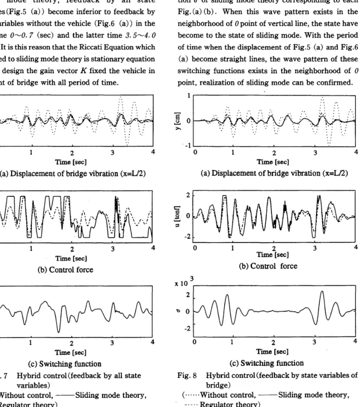
to the comparison of displacement response in Fig.5 (a) and Fig.6 (a). In this reason, the sliding mode theory has robustness for the time-varying system. In particular, sliding mode theory becomes good result compared with the regulator theory in case of the feed- back by state variables without the vehicle Fig.6 (a), because this theory has such immutability character for the external force. The straight response that is one of characteristic in sliding mode theory is realized in 2. 4--- 2. 8 (sec) (Fig.4 (a)), and0---0.6 (sec), 2. 4 ---2.8 (sec), 3.6'""4.0 (sec) (Fig.5 (a)). Limited to sliding mode theory, feedback by all state variables (Fig.5 (a)) become inferior to feedback by state variables without the vehicle (Fig.6 (a)) in the first time 0'""0.7 (sec) and the latter time 3.5'""4.0 (sec). It is this reason that the Riccati Equation which is applied to sliding mode theory is stationary equation and we design the gain vectorK fixed the vehicle in midpoint of bridge with all period of time.
Fig.5 Cb) and Fig.6 (b) show the control force cor- responding to displacement response. The solid line is sliding mode theory, and dashed line is regulator theory. For comparison of both theories in the control effectiveness, a limit is added to the control force by sliding mode theory, and the maximum is to become2 (ton/) . The chattering that is the weak point in sliding mode theory can be prevented, because the control force changes continually by using the feed- back gain Eq.(27).
Fig.5 (c) and Fig.6 (c) show the switching func- tion (J of sliding mode theory corresponding to each Fig. (a) (b). When this wave pattern exists in the neighborhood of0point of vertical line, the state have become to the state of sliding mode. With the period of time when the displacement of Fig.5 (a) and Fig.6 (a) become straight lines, the wave pattern of these switching functions exists in the neighborhood of 0 point, realization of sliding mode can be confirmed.
.. . -1 '-- -'- --' - ' - - - - ' ' - - _ - - J
o 2 3 4
Time [sec]
(a) Displacement of bridge vibration (x=LI2)
I
0 ---...» ..
-1 L . - - ' - - - - ' ...- - '_ _~
o
2 3 4Time [sec]
(a) Displacement of bridge vibration (x=U2)
I
0»
2
!;;"
c: 0
~::l
-2
0 2
Time [sec]
(b) Control force
3
2
!;;"
! c:
~
::l
-2
4 0 2
Time [sec]
(b) Control force 3
0 2 3 4
Time [sec]
(c) Switching function
Fig. 8 Hybrid controlCfeedback by state variables of bridge)
C' ...Without control, --Sliding mode theory, -.-. - Regulator theory)
x 10 3r-- ---.
2
b 0
-2
o
2 3 4Time [sec]
(c) Switching function
Fig. 7 Hybrid controlCfeedback by all state variables)
(···Without control, --Sliding mode theory, - .- .- Regulator theory)
x103 2
b 0
-2
In this time, displacement response of the bridge will slide on the intersection of hyperplane.
(3) Case of the Hybrid Control
Fig.7 and Fig.8 show comparison of sliding mode theory with regulator theory in case of feedback by all states variables and feedback by state variables ex- cept the vehicle for the hybrid control. Fig. (a) shows displacement response in midpoint of the bridge,Fig.
(b) shows control force, and Fig. (c) shows switching function of sliding mode theory. As the simulation results, sliding mode theory is generally superior to the regulator theory according to Fig.7 (a) and Fig.8 (a), but the difference of both theories is smaller than the active control. InO.5~O.8 (sec), 2.5~2.8 (sec) (Fig.6 (a)) and O~O.5 (sec) (Fig.8 (a)), flat responses are realized in sliding mode control. In sliding mode theory, feedback by all state variables (Fig.7 (a)) becomes inferior to feedback by state variables except the vehicle (Fig.8 (a)) at the first time and latter time response. This reason is that the Riccati Equation which is applied to sliding mode theory is stationary equation. Limited to sliding mode theory, when hybrid control response are compared with active control of Fig.5 and Fig.6, it can be con- fermed that hybrid control becomes more effective.
Fig.7 (b) and Fig.8 (b) show the control force cor- responding to displacement response. Same as the ac- tive control, the parameter is designed to became the maximum of control power to 2 (tonf). So, in sliding mode theory, the control force is limited. The chatter- ing can be prevented, because the control force changes continually by using the feedback gain Eq. (27) .
Fig.7 (c)and Fig.8 (c) show the switching function
(J of sliding mode theory corresponding to each Fig. (a) (b). When the parts of displacement response Fig. (a) are to be flat lines, the switching function (J corresponding to these displacement shifts to aroundO.
Therefore, when the displacement response is to be flat, the sliding mode is realized.
5. CONCLUSION
In this study, sliding mode theory was applied to ac- tive and hybrid control, and we had confirmed the ef- fectiveness of sliding mode theory.
The results are summarized as following.
(1) An example of road roughness had made from power spectral density, and the modeling of bridge- vehicle system in active and hybrid control have been done. The expressions of sliding mode theory for these control had made. The chattering which became a problem in sliding mode theory have been prevented.
(2) As the simulation results of the active control in particular, it was confirmed that the sliding mode theory has superior control effectiveness to the regulator theory. It was not all period of time because of external force acting continually, but straight response that was one characteristic of sliding mode theory had been realized.
(3) The feedback by all state variables has became in- ferior to the feedback by state variables except the vehicle in the first time and latter time of then response.Itwas this reason that the Riccati Equa- tion which was applied to sliding mode theory was stationary equation.
(4) In comparison of the active control with hybrid control by sliding mode theory, it has been confirm- ed that the hybrid control was able to realize superior control.
(5) From wave pattern of the control force, it has been confirmed that the chattering was able to be prevented because the control force changed con- tinually.
REFERENCES
I) M.Abdel-Roman and H.H.E.Leipholz : Active Control of Flexible Structures,ASCE,J.of the Struc- tural Division,Vo1.l04, No.ST8, pp.1251-l266, 1978.
7.
2) T.Okabayashi, S.Oguchi, T.Kaga: Active control of highway bridge vibration under a moving vehicle by several feedback control laws, Journal of Struc- tural Engineering,Vo1.42A,pp.731-738, 1996.3. (in Japanese)
3) H.Yamaguchi, T.Masuda, A.Ito : Dynamic characteristics of bridge-vehicle coupled system and its robust control, The Japan Society of Mechanical Engineers, Motion and Vibration Con- trol, No.95-28, pp.27l-274, 1995.7. (in Japanese) 4) K.Nonami, K.Den: Sliding mode control, 1994.10. (in
Japanese)
5) A.Ishigame, T.Furukawa, S.Kawamoto, T.
Taniguchi: Sliding mode controller design based on fuzzy Inference for nonlinear systems,IEEE Trans.Ind,Electron.,
Vol.40 , No. 1, pp.64-70, 1993. 2.
6) H.Ono: Mathematica DSP and Control, Toppan, 1992.10. (in Japanese)
7) S.Ishii, K.Nonami, H.Nishimura, O.Nakada : Sliding mode control for tower structure with hybrid dynamic vibration absorber, The Japan Society of Mechanical Engineers, Motion and Vibra- tion Control, No.930-42, pp.418-423, 1993.7. (in Japanese)
8) K.Iwamoto, T.Ito, K.Nonami, H.Nishimura: Ac- tive vibration control of flexible structure by fre- quency-shaped sliding mode control with ,usynthesis theory, The Japan Society of Mechanical Engineers, Motion and Vibration Control, No.95-28, pp.120-123, 1995.7. (in Japanese)
9) K.Nonami, K.Nishina : Discrete time sliding mode control of zero power magnetic bearing system, The Japan Society of Mechanical Engineers, Motion and Vibration Control, No.95-28, pp.
33-36,1995.7.
10) M.Nibe, M.Yokoyama, Y.Iwata: Antilock brak- ing system using sliding mode control, The Japan Society of Mechanical Engineers, Motion and Vibra- tion Control, No.95-28, pp.305-308, 1995. 7. (in Japanese)
11) C.Y.Su, T.P.Leung : A sliding mode controller with bound estimation for robot manipulators, IEEE Transactions on Robotics and Automation, Vol.9, No.2, pp.208-214, 1993.4.
12) S.N.Singh, A.Iyer : Nonlinear decoupling sliding mode control and attitude control of spacecraft, IEEE Transactions on Aerospace and Electronic Systems, Vo1.25, No.5, pp.621-633, 1989.9. (in Japanese)
13) J. Zhang, T.H.Barton : Robustness enhancement of dc drives with a smooth optimal sliding-mode control, IEEETransactions on Industry Applica- tions, Vol;. 27, No.4, pp.97-104, pp.686-693,1991, 7-8.
14) T.Okabayashi, T.kaga : Optimal design of tuned mass dampers for highway bridge vibration under a moving vehicle, Proceedings of Colloquium on Bridge Vibration,PARTB,pp.273-79,1995.11. (in Japanese)