Two Rule-based Building-block Architectures for Policy-based Network Control
Yasusi Kanada
Central Research Laboratory, Hitachi, Ltd.
Higashi-Koigakubo 1-280, Kokubunji, Tokyo 185-8601, Japan [email protected]
Abstract. Policy-based networks can be customized by users by injecting programs called policies into the network nodes. So if general-purpose functions can be specified in a policy-based network, the network can be regarded as an active network in the wider sense. In a policy-based network, two or more policies must often cooperate to provide a high-level function or policy. To support such build- ing-block policies, two architectures for modeling a set of policies have been developed: pipe- connection architecture and label-connection architecture. It is shown that rule-based building blocks are better for policy-based network control and that the label-connection architecture is currently better.
However, the pipe-connection architecture is better in regards to parallelism, which is very important in network environments.
1. Introduction
Active networks are networks that are customizable by users, and their behavior can be modified by injecting programs. An appropriate first step toward active networks is to build an extensible policy-based net- work, because such a network can be customizable by users by deploying policies and because programs, which are called policies, can be injected into the nodes in a policy-based network. For example, QoS (Quality of Service) policies, which may be device- dependent, can be deployed to QoS-ready routers, so the network is customized to each user. Each user can have their own virtual network with customized QoS parameters such as a specific bandwidth or delay. The function of policies has been limited to a certain area, e.g., QoS or security, but it can be extended. If it is extended and the policy-based network becomes gen- eral-purpose, it becomes an active network.
In policy-based networks, two or more policies must often work together. For example, in Diffserv, a policy for marking a DSCP (Diffserv Code Point) and a policy for queue control, which operates on the same packets, must cooperate. They must cooperate be- cause the latter tests the DSCP that the former marks.
This is a simplest case of cooperation, but there are probably more complicated cases. A higher-level function or policy of the network is provided by a combination of lower-level functions or building- block policies.
To build a building-block-based policy system, Ka- nada proposed the first version of a rule-based com- ponent architecture as a MIB [Kan 99][Kan 00a], and he also developed an architecture based on a logic programming language [Kan 00b]. In these architec- tures, a policy is constructed using rule-based building blocks, or small policies, which are connected by vir-
tual flow labels [Kan 99] or logical variables [Kan 00b]. The first architecture was restricted to a QoS domain and the building blocks were built-in there, but the second architecture was general-purpose and building blocks could be created by combining preexisting building blocks.
In the current work, two new building-block archi- tectures based on the above two architectures have been developed. One is a pipe-connection architec- ture, which is a refinement of the second architecture, and the other is a label-connection architecture, which is a generalized version of the first architecture. In Section 2, the technical requirements for policy-based networking are investigated and the reason such ar- chitectures are required is explained. The two build- ing-block architectures are described in Section 3.
Examples of DiffServ configuration for routers are given in Section 4. The two architectures are com- pared in Section 5.
2. Why Rule-based Building Blocks?
Policy-based networks are originally developed for reducing the complexity in configurations of a net- work and its nodes. Policies are replacements of ven- dor- and device-dependent configuration commands, and they will soon be standardized by the IETF (Internet Engineering Task Force) Policy Framework Working Group. Policies are derived from SLSs (service-level specifications). An SLS is a specifica- tion regarding the behavior of the network and it is derived from an SLA (service-level agreement), which is a contract between a network operator and a user or between two or more network operators.
There are five technical requirements regarding policy-based (active) networks. The first requirement is that an SLS should be translated into policies easily by hand or mechanically if the SLS is simple. An SLS
is described declaratively, but not procedurally, by using a natural language or a formal language. If a policy depends on the specific procedure that imple- ments the required function, it is not easily generated from the SLS. So the policy should be declarative. In particular, a policy is usually considered as a collec- tion of if-then rules such as
if (condition) action;
because it is usually considered easier to translate an SLS into if-then rules.
The second requirement is that a policy must be executable. A policy is not just data but a program because it changes the behavior of a network or net- work nodes. So when copies of the policy are de- ployed to network nodes, they must be executable.
The third requirement is that dynamic modification of a policy must be possible. Because the network never stops, a policy is often modified while it is be- ing used. So a policy must be modular. If a policy consists of mutually independent rules, a rule can be added, modified, or removed without affecting other rules.
The fourth requirement is that, even if the SLS is complicated, translating the SLS into policies must be possible. A complicated SLS should be expressed in a structured form, so the policies that are derived from the SLS should also be structured. Thus, there should be means that structure the policies. This means a policy should be constructed from components or building blocks.
The fifth requirement is that an optimized policy should be expressible by using the same architecture.
A naïvely expressed policy may be inefficient. Such a policy should be optimized automatically or by hand.
Both the original policy and the optimized policy must be represented by the same language. Otherwise, it is difficult to prove they are semantically equivalent.
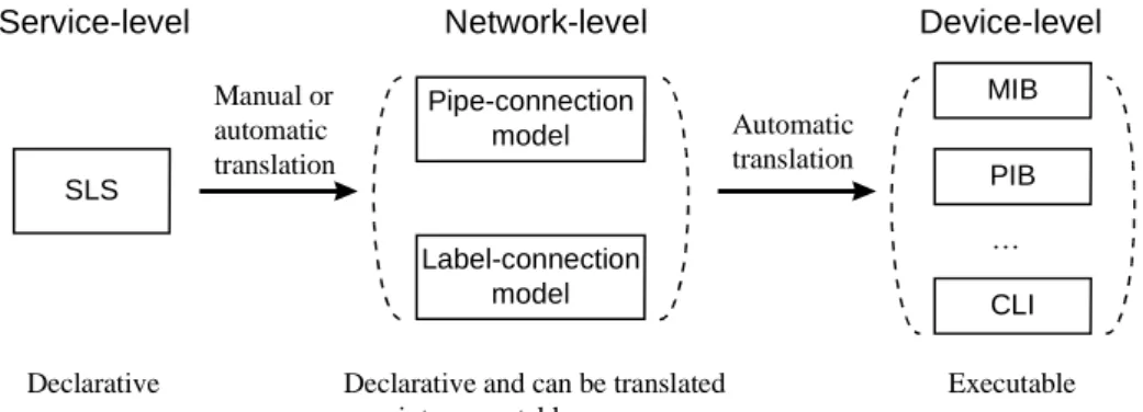
A method that meets these requirements is to rep- resent policies by a rule-based building-block archi- tecture. A possible translation process from SLS to device configurations through rule-based building blocks is illustrated in Fig. 1.
The first three requirements can be satisfied by us- ing rule-based models or languages that are similar to Prolog or OPS5 [For 81]. Defining a policy declara- tively and translating it into an executable program is difficult if the policy is complicated. However, such translation is easier if the policy representation is properly selected. In the field of artificial intelligence, knowledge representations were extensively studied in the 1970s and 1980s, and rule-based programming languages, especially logic programming languages (such as Prolog) and languages for developing pro- duction-system-based expert systems (such as OPS5), were developed. These languages are declarative and executable at the same time. We can apply the results of such research to policy-based networking. In the languages, rules can be written as mutually inde- pendent rules; i.e., rules can be defined such that only one rule can be applied in any specific situation even if the order of rules is changed.
The fourth and fifth requirements can be satisfied by using a component-based architecture. A compli- cated policy can be expressed by using building blocks. Complexity can be reduced by defining a larger building block as a collection of building blocks. Both primitive and composed building blocks are rule-based and follow the same semantics if a logic programming language is used. A policy can be optimized by program transformations. If the opti- mization is local, it is done by replacing a set of building blocks by another set of building blocks.
3. Two Building-Block Model Architectures
3.1 Structure of Building Blocks
In both architectures, a policy or policy rule consists of building blocks and connections between them. A building block is a rule or a set of rules. The structure of a building block is roughly similar to that of a pol- icy in the policy information model [Moo 00], and the structure of a rule is also similar to that of a policy rule. A building block is executed as follows. A rule is selected if the input packet matches the condition
Pipe-connection model SLS
Label-connection model
MIB
PIB
CLI Manual or
automatic translation
Automatic translation
…
Service-level Network-level Device-level
Declarative Declarative and can be translated into executable program
Executable
Fig. 1. Service- to device-level policy-translation process
specified in the rule. Then the action specified in the rule is executed and an output packet is generated. If no condition in the rule set matches the input packet, no action is taken and no packet is outputted. So a building block inputs a stream of packets, or a flow, filters it, and maybe splits it into multiple flows or merges multiple flows into one.
A network node can be modeled as a building block or a collection of building blocks. A building block has input ports and output ports. Building blocks are connected by connecting each input port and output port. So the function of the network node can be rep- resented by a DAG in which the vertices represent the building blocks. The whole network can also be modeled by a building-block model. Each function in the network domain can be represented by a DAG.
The task of a policy server is to decompose this DAG into subgraphs and to deploy each subgraph to each router in the domain. The edges between the sub- graphs are mapped to the lines between the routers.
3.2 Pipe-connection Architecture
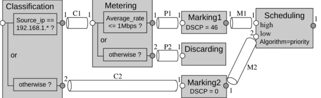
The pipe-connection architecture is explained in Fig. 2. In this architecture, each building block has a fixed number of input ports and output ports. Each input or output port has a port identifier. Port identi- fiers can be numbers or alphanumeric identifiers, but they are assumed to be ordinal numbers here. The example used in Fig. 2 is a Diffserv router configura- tion, which will be explained more in the next section.
Building blocks are connected by pipes. The be- ginning of a pipe is connected to an output port of a building block. The end of the pipe is connected to an input port of another building block. A packet stream flows in each pipe. When a packet flows into a building block, one (or zero) packet flows out from the building block. Pipes are uniquely identified by their tags. Packets come into a building block through an input port and go out through an output port. Usu- ally, a packet is outputted to only one of the output ports, i.e., packets are not duplicated implicitly, and two packets that come from the same or different input ports are never merged into one packet.
In Fig. 2, six building blocks are given: Classifica- tion, Metering, Marking1, Discarding, Marking2, and
Scheduling. The Classification and Metering building blocks contain two sub-blocks, or rules. Other build- ing blocks can contain only one sub-block. The Clas- sification and Metering building blocks are connected by a pipe named C1, and C1 connects the output port 1 to the input port 1. The Classification building block has two output ports. Each packet that flows into this building block flows out from only one of these output ports. A Discarding building block has no output ports. So packets that flow into a discarding building block never flow out. The Scheduling building block has two input ports, but other building blocks have one input port in Fig. 2.
This architecture can be properly represented by using a backward-chaining predicate-logic-based language similar to GHC [Ued 85], Concurrent Prolog [Sha 86], or Parlog [Cla 86]. These languages are suited to describing data stream processing. So the pipe-connection models can be expressed directly. A language for this architecture, which is called SNAP (Structured Network programming by And-Parallel language), was defined by Kanada [Kan 00b]. In SNAP, each building block is represented by a predi- cate, and a predicate consists of clauses (i.e., rules).
Building blocks are connected by logical variables.
So a logical variable is used as a pipe. The model in Fig. 2 can be expressed in SNAP as follows:
ef_ingress(Si, So) :– // Building block ef_ingress // inputs stream Si and outputs stream So.
or( filter[Source_IP = 192.168.1.*](Si, C1) | // Packets (in Si) whose source IP subnet // is 192.168.1.* are outputted to C1.
or( meter[Average_rate_max = 1Mbps](C1, P1) | // Packets (in C1) within the bandwidth // limit are outputted to P1.
mark[DSCP = 46](P1, M1) // Packets in P1 are marked and // outputted to M1.
; otherwise(C1, P2) |
// Packets (in C1) that do not meet // other (only one here) conditions in // the case structure are outputted to P2.
discard(P2)
// All the packets in P2 are discarded.
)
; otherwise(Si, C2) |
// Packets (in Si) that do not meet other conditions // in the case structure are outputted to C2.
Metering Classification
otherwise ? Discarding
Scheduling
Algorithm=priority high
or low Source_ip ==
192.168.1.* ?
Marking1
DSCP = 46
or
C1 P1
P2
M1
Marking2
DSCP = 0 C2
M2 Average_rate
<= 1Mbps ?
otherwise ?
1 1
2
1 1
2 1
1
1 1
2
1
1
1
Fig. 2. A model using the pipe-connection architecture
mark[DSCP = 0](C2, M2)
// Packets in C2 are marked and outputted to M2.
),
schedule[Algorithm = priority](M1, M2, So).
// Streams M1 and M2 are merged into So.
// A queue is assigned to M1,
// and another queue is assigned to M2.
// They are scheduled by a priority // scheduler. The priority of M1, which is // the first argument, is higher.
This program defines a building block calld ef_ingress, which has one input port and one output port. This example will not be explained further here, but an explanation of a very similar program can be found in Kanada [Kan 00b].
3.3 Label-connection Architecture
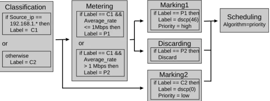
The label-connection architecture is explained in Fig. 3. In this architecture, each building block has only one input port and one output port. Building blocks contain one or more rules. For example, both the Classification and Metering building blocks have two rules. The execution order of building blocks is constrained. The order constraints are represented by a directed graph. In Fig. 3, six building blocks are connected by directed edges. For example, the Classi- fication building block is connected to the Metering and Marking2 building blocks. So the Metering and Marking2 building blocks will be executed just after executing the Classification building block. Whether the Metering or Marking2 building block is executed depends on the conditions of the rules in the Metering and Marking2 building blocks and the value of the packet. If the packet matches a condition in the Me- tering building block, this building block is executed.
Each rule attaches a tag called a label, which con- tains an integral value, to each packet in a flow or to a packet flow. There are two types of label. One type is a real label that may be inside the packet, for ex- ample, as a DSCP or an MPLS label. The other type is a virtual label or VFL (virtual flow label, named
“Label” in Fig. 3) (Fig. 4). The value of the VFL is not put on the packet and the VFL can be regarded as a tag put outside of the packets (Fig. 4). Only one VFL can be attached to a flow or packet. In Fig. 3,
the rules in the Classification and Metering building blocks assign a VFL, and the Marking1 and Marking2 building blocks assign a DSCP as the label. The ini- tial value of a VFL is “undefined” (a specific value).
A flow or a packet may have two or more tags. In Fig. 3, Marking1 and Marking2 building blocks assign a value to a tag named “Priority”. Tags except the label are called attributes. The priority attribute is used for the priority scheduling in Scheduling building block.
The order of execution can be uniquely defined by defining and referring to VFL values appropriately.
For example, the first rule in the Classification build- ing block assigns value C1 to the VFL, and the second rule assigns value C2. The rules in the Metering building block assumes the VFL value is C1. So these rules can be executed only after executing the first rule in the Classification building block. The only rule in the Marking2 building block assumes the VFL value is C2. So this rule can be executed only after executing the second rule in the Classification build- ing block.
46 DS field
1000
(a) DSCP (a real label) (b) A VFL
Packet Packet
Fig. 4. DSCP and Virtual flow label
Label-connection architecture can be properly rep- resented by using a language for production systems similar to OPS5 or other forward-chaining rule-based languages for developing expert systems. In such a language, each rule is an if-then rule; i.e., each rule has a condition and actions. This rule structure is very similar to that of a policy rule in the policy informa- tion models [Moo 00][Sni 00]. However, conven- tional languages for production systems have no method for structuring rules (i.e., building blocks) as sets, and for giving a partial order to them. So we
Metering Classification
if Label == C1 &&
Average_rate
> 1 Mbps then Label = P2
Discarding
Scheduling
Algorithm=priority
or if Source_ip ==
192.168.1.* then Label = C1
Marking1
or
Marking2
if Label == C1 &&
Average_rate
<= 1Mbps then Label = P1
otherwise Label = C2
if Label == C2 then Label = dscp(0) Priority = low if Label == P1 then
Label = dscp(46) Priority = high
if Label == P2 then Discard
Fig. 3. A label-connection model
should define a new language to represent this archi- tecture. The model in Fig. 3 can be expressed by us- ing such a language as follows:
MODULE ef_ingress IS
RULE SET Classification, Metering, Marking1, Dis- carding, Marking2,
Scheduling;
RULE SET ORDER
Classification –> Metering, Marking2;
Metering –> Marking1, Discarding;
Marking1, Discarding, Marking2 –> Scheduling;
RULE SET Classification IS
IF Source_ip == 192.168.1.* THEN Label = C1;
OTHERWISE Label = C2;
…
RULE SET Scheduling IS
IF true THEN// This scheduler is always used.
Algorithm = priority;
END ef_ingress;
This program defines a building block called ef_ingress. Ef_ingress contains six rule sets, their execution order is defined by RULE SET ORDER definition, which is followed by RULE SET defini- tions. The execution order can be regarded as a defi- nition of a directed graph. Because the contents of RULE SET definitions are the same as shown in Fig. 3, most of them are omitted here.
4. Differentiated Services Using the Building-Block Models
4.1 Brief Introduction to Diffserv
In the IETF, many working groups (WGs) are con- cerned with Internet QoS. In particular, the Integrated Services (IntServ) WG specified guaranteed per-flow QoS [Wro 97][She 97], and the Differentiated Serv- ices (Diffserv) WG have been working on class-based QoS assurance [Ber 99]. “Per-flow” means that each flow of packets between a source end-point and a des- tination end-point is treated individually. “Class- based” means that flows are classified into
service classes, and flows in the same service class are treated in the same way. Per-flow control enables more accurate QoS control, but requires much more network node re- sources. Because the resources are limited, the class-based approach, i.e., DiffServ, seems more practical for the Internet.
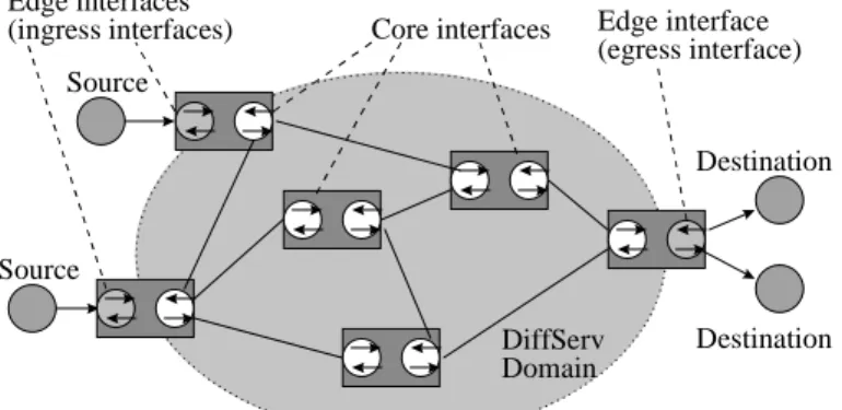
A network domain, which will usually be an autonomous system (AS), can be modeled as shown in Fig. 5. In DiffServ, the domain is a part of networks in which the same set of PHBs (per-hop behaviors) [Bla 98] is used.
A DSCP (differentiated services code point) [Nic 98] is assigned to each PHB in this do- main. The network consists of network
nodes, such as routers, and the lines between them.
The network interfaces of the routers that are con- nected to computers are called edge interfaces, and the interfaces that are connected between routers are called core interfaces. Edge interfaces that are con- nected to packet sources are called ingress interfaces, and those connected to packet destinations are called egress interfaces. Because communication lines are usually bidirectional, edge interfaces usually work as both ingress and egress interfaces. An interface may also be used as both an edge and a core interface.
In a Diffserv network, IP (Internet protocol) pack- ets are classified at ingress interfaces and are marked in their DS (differentiated services) field [Nic 98].
The value in the DS field is called the DSCP and in- dicates the service class that the packet belongs to. At core interfaces, the QoS conditions of the packets are controlled according to the DSCP.
IP packets are classified by using a classifier. A classifier uses a set of filtering conditions, and each condition corresponds to an action. A combination of a condition and a corresponding action can be re- garded as an if-then rule. This rule works for each packet. The behavior of an interface can be specified by using a set of if-then rules. Classifiers used at in- gress interfaces are called MF (multifield) classifiers.
An MF classifier mainly checks the following five items: source and destination IP address, IP protocol, source and destination IP ports. The action taken as the result of MF classification is usually marking, which means assigning a DSCP to the DS field of the packets. Classifiers are also used at core and egress interfaces in DiffServ, but in a different way. They are called BA (basic aggregate) classifiers. A BA classifier checks the DSCP. A resulting action may be to assign a priority to the queue used for the packets.
4.2 Building Blocks for DiffServ
Six types of primitive building blocks for DiffServ are defined: filtering, metering, marking, discarding, scheduling, and merging rules. A previous version of these building blocks was described by Kanada
DiffServ Domain Edge interfaces
(ingress interfaces) Source
Source
Destination
Destination Core interfaces Edge interface
(egress interface)
Fig. 5. A Diffserv network
[Kan 00b]. The building blocks defined here are simi- lar to objects defined in Diffserv MIB [Bak 00], Diff- serv PIB [Fin 00], or QoS Information Model [Sni 00]. However, the models described in this sub- section is different from Diffserv MIB and PIB be- cause it is rule-based, and the building blocks in the models are more fine-grained than those in the infor- mation model. Most of these building blocks can be used as is, can be enhanced for services other than DiffServ, or can be used with other types of building blocks.
Filtering, marking, and discarding rule sets are ap- plied to a packet stream only once because repetitive application of these rules is unnecessary. Metering, merging, and scheduling rules can be applied to a packet stream two or more times because repetitive applications of these rules are sometimes necessary.
Rules are described using the following syntax:
ruleTypeName[parameters].
Filtering rules represent a part of an MF or BA classifier. A filtering rule tests the IP packet header of each packet. This means it tests one or all of the DSCP, source and destination IP addresses, IP pro- tocol, source and destination IP ports, and so on.
These values are specified as parameters in the filter- ing rule. If a packet meets the condition in the rule, it is outputted to the stream. Otherwise it is dropped.
Examples of filtering rules are filter[Source_IP = 192.168.1.*].
// A part of an MF classifier.
filter[DSCP = 46]. // A part of a BA classifier.
In a pipe-connection model, filtering rules have only one input port and one output port, and the names of pipes that are connected to the input and output ports of the rules must be specified. If the input pipe name is Si and the output pipe name is So, the rule can be described as
filter[Source_IP = 192.168.1.*](Si, So).
Metering rules only pass the traffic that is confor- mant to the profile contracted by an SLS (service- level agreement). Metering rules can be implemented by using a token-bucket meter or some other type of meter. The average maximum information rate and the bucket size can be specified as parameters. An example of a metering rule is
meter[Average_rate_max = 1Mbps].
In a pipe-connection model, metering rules have only one input port and one output port.
Marking rules write a DSCP into the DS field of the packets in the input stream. All the packets are out- putted to the output stream. The only parameter for marking rules is the DSCP. An example is
mark[DSCP = 46].
In a pipe-connection model, marking rules have only one input port and one output port.
Discarding rules discard all the packets in a stream.
There are two types of discarding rules in a label- connection model: an absolute discarding rule and random discarding rules. The absolute discarding rule discards all the packets. Random discarding rules discard packets by using a weighted random-early- discard (WRED) algorithm. The function of random discarding rules is included in scheduling rules in a pipe-connection model, so they do not exist. There are no parameters to be specified for the absolute discarding rule,
absoluteDiscard.
In a pipe-connection model, the absolute discard rule has only one input port and no output port. An exam- ple of random discarding rule is
randomDiscard
[QMin = 10kB, QMax = 20kB, PMax = 0.1].
Scheduling rules are used for merging streams through scheduling. The parameters of a scheduling rule specify the method and parameters for enqueuing and dequeuing control. The scheduling algorithm and its parameters can be specified in scheduling rules, which can also be used for shaping control. The maximum and minimum output rate (or both) can be specified. Examples are
schedule.// Input packets are queued until they can // go out. The queue size is default.
schedule[Algorithm = priority].
// Input packets are scheduled using a priority scheduling algorithm.
// Input packets should have a priority // attribute (See Fig. 3).
In a pipe-connection model, merging packet flows must be explicitly specified. Merging rules are used to merge, without buffering, two or more flows.1
merge(Si1, Si2, Si3, So).
// Flows through pipes Si1, Si2, and Si3 // are merged into So.
A merging rule is not specific to Diffserv, and is usu- ally required for the pipe-connection architecture. On the contrary, streams can be implicitly merged and no merging rules are necessary in a label-connection model. No scheduling functions are used for the flows inputted to a merging rule, because merging without buffers is required here. If buffering is required, scheduling rules must be used for the merging flows.
In a label-connection model, the execution order must be specified. The order for Diffserv is described in Fig. 6. Metering rules can be repeated because a flow can be policed with two or more conditions, and two or more out-profile traffic streams can be handled differently. Scheduling rules can be repeated because a hierarchical scheduler or shaper is sometimes re- 1A merging rule is necessary for this architecture because of the single-assignment constraint.
quired.
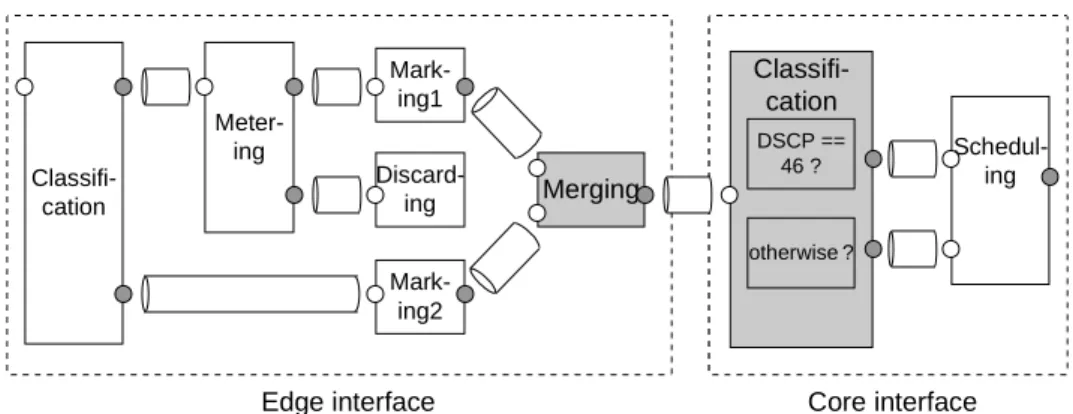
4.3 Expedited Forwarding Service Configurations Expedited forwarding (EF) service [Jac 99] is a virtual-leased-line service. Each microflow is policed and aggregated into a flow at the ingress edge inter- faces. Packets with this DSCP are forwarded in high priority in core interfaces.
An example of an SLS for an EF service is as fol- lows:
IF the flow is from user A (the Source IP address is 192.168.1.*) THEN
IF the information rate is within 1Mbps THEN Treat the flow as an EF traffic;
OTHERWISE Drop the packets;
OHERWISE
Treat the flow as a best effort traffic;
The configuration for this service can be represented by the pipe-connection model in Fig. 2 and by the label-connection model in Fig. 3. The copies of the classifier, meter, markers, and discarder are deployed to the ingress edge interface, and the copies of the scheduler are deployed to each core interface. In the pipe-connection model, Merging and (BA) Classifica- tion building blocks must be added to split the pro- gram into an edge and a core interface as shown in Fig. 7, because a tagged pipe cannot be used between these interfaces. No more building blocks are needed in the label-connection model.
4.4 Assured Forwarding Service Configurations Assured forwarding (AF) services [Hei 99] can be used for a wide range of services. An example is an Olympic service. There are gold, silver, and bronze classes of services in an Olympic service. The gold class gets the highest priority, the silver the second, and the bronze the third. The bronze service gets even higher priority than the best effort service. In each AF class, there may be three different subclasses of traffic that share the same queue in each network node but have different queue depths or different parameters for WRED. There are three subclasses for each class, AFn1 to AFn3, assigned for AF services in RFC2597 [Hei 99].
An example of core interface configuration for an AF service is shown in Fig. 8. Only the core con- figuration for AF1 is shown here. The input stream is forked into four, AF11, AF12, AF13, and other streams, by a BA classifier. Streams AF11 to AF13 are merged using a scheduler with only one queue but three different discarding thresholds. Packets in stream AF11, i.e., the first argument for “schedule”, are discarded only when the queue is full, i.e., when the queue is filled with 100 kB of data. Packets in stream AF12, i.e., the second argument, are discarded when the queue is filled with 80 kB of data. Packets in stream AF13; i.e., the third argument, are discarded when the queue is filled with 60 kB of data. Packets in AF streams and those in other (best effort) streams are merged by using a weighted round robin (WRR) scheduler.
Filter
Meter Marker
Absolute Discarder
Scheduler Random
Discarder
Fig. 6. Execution order of building blocks in the label-connection model
Meter- ing Classifi-
cation
Discard- ing
Schedul- ing Mark-
ing1
Mark- ing2
Core interface Merging
Classifi- cation
Edge interface
DSCP ==
46 ?
otherwise ?
Fig. 7.Ingress edge and core interface configurations for an EF service in the pipe-connection model
Scheduling1 and Scheduling2, which correspond to queues, enter packets into queues, and Scheduling3, which corresponds to a packet scheduler, pulls off packets from Scheduling1 and Scheduling2 according to the scheduling algorithm. Scheduling1 and Sched- uling2 in the label-connection model contain no other actions than replacing labels. However, they are de- scribed here because they represent necessary queues.
5. Comparisons
Five major differences between the two building block architectures are explained below.
1. Rule structures: A rule in the label-connection architecture consists of if-then rules, but a rule in the pipe-connection architecture does not necessar- ily consist of if-then rules. If-then rules can be simulated by using the pipe-connection architec- ture, but the syntax of a rule is different: it consists of building blocks instead of a condition and an ac- tion. A building block in SNAP consists of a guard and a body, and a guard is similar to a condition and a body is similar to an action. However, their semantics are different. Thus, if the pipe- connection architecture is to be used, a method that makes policy development easier must be devel- oped.
2. Control-flow specification: Explicit control flow is not necessarily specified in the pipe-connection ar-
chitecture because the control flow is derived from the dataflow that is specified by pipes. However, the label-connection architecture needs a loose con- trol-flow specification because the control flow is not uniquely specified by tags on packets. Thus, the execution order of policies must be explicitly specified in the label-connection architecture.
3. Multiple I/O ports and modularity: In the pipe- connection architecture, building blocks with mul- tiple input or multiple output ports are required, but in the label-connection architecture, only an input and an output ports are required. In the former, if there are two or more inputs/outputs with different roles, they must be distinguished by ports. Thus, multiple ports are necessary. On the contrary, in the latter, different roles are not distinguished by ports but are distinguished by flow labels. aThis difference in roles causes the difference in the modularity of schedulers or mergers. A scheduler (for Diffserv) usually input packets from two or more rules. In a pipe-connection model, each out- put port of the rules must be connected to an input port of the scheduler by a pipe. Thus, the number of input ports must be incremented when a rule is added. However, in a label-connection model, the number of input ports is always one. Thus, there is no need to modify the scheduling rule. A merger is only used in pipe-connection models. The number Scheduling2
Classification
DSCP==12 ?
or
1 1 AF11
2 AF12
otherwise ? DSCP==14 ?
DSCP==16 ?
3 AF13
4 BE
Scheduling1 DropAlgorithm=
WRED Qmax=100kB
Qmax=80kB
Qmax=60kB 1
2
3
4
1
Scheduling3 1 Algorithm= WRR
2 2
(a) A pipe-connection model Classification
if DSCP==12 then Label = D1 if DSCP==14 then
Label = D2 if DSCP==16 then
Label = D3 otherwise
Label = S2
Scheduling1
Scheduling2
Scheduling3
if Label == S1 then Label = S2 Enqueue
if Label == S2 then Enqueue
if Label == S2 then Algorithm = WRR RandomDiscarder
if Label == D1 then Label = S1 DropAlg=WRED Qmax = 100kB if Label == D2 then
Label = S1 DropAlg=WRED Qmax = 80kB if Label == D3 then
Label = S1 DropAlg=WRED Qmax = 60kB
(b) A label-connection model Fig. 8. Core interface configuration for an AF service
of input ports must be incremented when a rule is added too. On the contrary, flows are merged im- plicitly in a label-connection model.
4. Tag usage: There are two differences in tag usage in the two architectures. One difference is that each pipe must have a unique tag in the pipe- connection architecture, but the same labels and tags can be used multiple times in the label- connection architecture.1 Thus, DSCPs can be used as flow labels. After marking, DSCPs are usually not changed within a Diffserv domain. So they are not unique in a set of policies. For the same reason, MPLS EXPs or labels may also be used as flow labels.
The other difference in the usage of tags is that multiple tags can be attached to a flow or packet in the label-connection architecture, but only one tag can be attached to a pipe in the pipe-connection ar- chitecture. If different parameters are applied to different flows, the flows must be inputted to dif- ferent input ports. This condition causes the differ- ence in schedulers in the Diffserv examples.
Parameters for schedulers, such as a WRED pa- rameter (e.g., QMax = 100 kB) or scheduling prior- ity (e.g., Priority = high in Fig. 3) must be defined in the scheduling rule (not in the queuing rule) in the pipe-connection architecture. On the contrary, in the label-connection architecture, such parame- ters can be given as different tags. So a set of WRED parameters can be specified by a random discarder (See Fig. 8) instead of embedding them into a scheduler. Thus, the building blocks can be smaller and the design of building blocks is more flexible in the label-connection architecture.
5. Parallelism: Constraints on parallelism should be as few as possible in network environments. A pipe-connection model can be executed in parallel unless the order of packets must be preserved be- fore scheduling, but a label-connection model is a sequential execution model and paralellization has two difficulties. One is that the order of label and attribute assignments must not be reordered be- cause reordering them may change the semantics.
The other difficulty is that the execution order of rule sets is specified in a label-connection model, and this specification constrains the parallel execu-
1If flow labels are unique, all the rules can be put in a rule set and there is no need to specify the control flow. Then, the label-connection model is very similar to a pipe- connection model.
tion. (This constraint is caused by the second dif- ference.) SNAP, the language for the pipe- connection architecture, is based on parallel logic programming languages for describing parallel processing programs.
Differences 1, 3, 4 indicate that the label- connection architecture is superior. It is easier and advantageous to move from a conventional policy- based architecture to the label-connection architecture to make the policy-based system more general- purpose. However, difference 5 indicates that the pipe-connection architecture is superior. Although it is not very easy to move from the conventional archi- tecture to the pipe-connection architecture, the author believes there is reasons to do so: parallelism is nec- essary and the parallel execution semantics must be clear.
6. Conclusion
Two rule-based building-block architectures for mod- eling a set of policies — the pipe-connection architec- ture and the label-connection architecture — have been developed and it was found that the label- connection architecture is currently preferable, but the pipe-connection architecture is better in regards to parallelism, which is very important. Thus, the label- connection architecture is the solution that can be used right now, but the pipe-connection architecture will become more useful. That is, if the disadvantages can be eliminated by further study, the pipe-connection architecture may become the right solution.
Acknowledgments
The author thank Satoshi Yoshizawa from Hitachi America for his insightful comments on the previous version of this paper.
References
[Bak 00]Baker, Chan, F., K., and A. Smith: Manage- ment Information Base for the Differentiated Serv- ices Architecture, draft-ietf-diffserv-mib-04.txt, Internet Draft, July 2000.
[Ber 99]Bernet, Y., et al.: A Framework for Differen- tiated Services, draft-ietf-diffserv-framework- 02.txt, Internet Draft, February 1999.
[Bla 98]Blake, S., Black, D., Carlson, M., Davies, E., Wang, Z., and Weiss, W.: An Architecture for Dif- ferentiated Service, RFC 2475, December 1998.
[Cla 86]Clark, K., and Gregory, S.: PARLOG: Paral- lel Programming in Logic, ACM Trans. on Pro- gramming Languages and Systems, Vol. 8, No. 1, pp. 1–49, 1986.
[Fin 00]Fine, M., McCloghrie, K., Seligson, J., Chan, K., Hahn, S., Smith, A., and Reichmeyer, F.: Dif-
ferentiated Services Quality of Service Policy In- formation Base, draft-ietf-diffserv-pib-01.txt, In- ternet Draft, July 2000.
[For 81]Forgy, C. L.: OPS5 User’s Manual, Technical Report CMU-CS-81-135, Carnegie Mellon Univer- sity, Dept. of Computer Science, 1981.
[Hei 99]Heinanen, J., Baker, F., Weiss, W., and Wro- clawski, J.: Assured Forwarding PHB Group, RFC 2597, June 1999.
[Jac 99]Jacobson, V., Nichols, K., and Poduri, K.: An Expedited Forwarding PHB, RFC 2598, June 1999.
[Kan 99]Kanada, Y., Ikezawa, M., Miyake, S., and Atarashi, Y.: SNMP-based QoS Programming In- terface MIB for Routers, draft-kanada-diffserv- qospifmib-00.txt, Internet Draft, October 1999, http://www.kanadas.com/activenet/draft-kanada- diffserv-qospifmib-00.txt.
[Kan 00a] Kanada, Y.: Rule-based Modular Represen- tation of QoS Policies, Networking Architecture Workshop, pp. 106–113, IEICE (The Institute of Electronics, Information and Communication Engi- neers), February, 2000.
[Kan 00b] Kanada, Y.: A Representation of Network Node QoS Control Policies Using Rule-based Building Blocks, International Workshop on Qual- ity of Service 2000 (IWQoS 2000), pp. 161–163.
[Moo 00] Moore, B., Ellesson, E., Strassner, J., and Westerinen, A.: Policy Framework Core Informa- tion Model — Version 1 Specification, draft-ietf- policy-core-info-model-07.txt, Internet Draft, July 2000.
[Nic 98]Nichols, N., Blake, S., Baker, F., and Black, D.: Definition of the Differentiated Services Field (DS Field) in the IPv4 and IPv6 Headers, RFC 2474, December 1998.
[Sha 86]Shapiro, E.: Concurrent Prolog: A Progress Report, IEEE Computer, August 1986, pp. 44–59, 1986.
[She 97]Shenker, S., Partridge, C., and Guerin, R.:
Specification of Guaranteed Quality of Service, RFC 2212, September 1997.
[Sni 99]Snir, Y., Ramberg, Y., Strassner, J., and Co- hen, R.: Policy Framework QoS Information Model, draft-ietf-policy-qos-info-model-01.txt, In- ternet Draft, April 2000.
[Ued 85]Ueda, K.: Guarded Horn Clauses, Logic Programming Conference ’85, pp. 225–2236, 1985. Also in ICOT Technical Report, TR-103, Institute for New Generation Computer Technol- ogy, 1985, and in New Generation Computing, Vol. 5, pp. 29–44, 1987.
[Wro 97]Wroclawski, J.: Specification of the Con- trolled-Load Network Element Service, RFC 2211, September 1997.