仙台市/仙台市産業振興事業団
ロボット博士の基礎からのメカトロニクスセミナー
第13回
デジタルセンサをマイコンにつなぐ
仙台市地域連携フェロー 熊谷正朗 添付技術資料
出典:
○アバゴ・テクノロジー株式会社 (Avago Technologies)
Laser Mouse Sensor ADNS-6010
データシートAV02-1410EN December 4,2009
○インベンセンス社 (InvenSense Inc.)
MPU-6000 and MPU-6050 Product Specification Revision 3.3 Document Number: PS-MPU-6000A-00 Revision 3.3 5/16/2012
MPU-6000 and MPU-6050 Register Map and Descriptions Revision 4.0 Document Number: RM-MPU-6000A-00 Revision 4.0 03/09/2012
本文書は、WEB 上で入手できるデータシートを、セミナーにおけるデジタルセンサの実 例の解説のために、一部抜粋、引用したもので、それぞれの部分の著作権は両社にありま す。正確な情報は、両社のオリジナルのデータシートを参照ください。
ADNS-6010
Laser Mouse Sensor Data Sheet
Description
The Avago Technologies ADNS-6010 sensor along with the ADNS-6120 or ADNS-6130-001 lens, ADNS-6230- 001 clip and ADNV-6340 laser diode form a complete and compact laser mouse tracking system. It is the world’s first laser-illuminated systems enabled for high performance navigation. Driven by Avago Technologies LaserStream, it can operate on many surface that prove difficult or traditional LED-based optical navigation. It’s high-performance architecture is capable of sensing high-speed mouse motion -with resolution up to 2000 counts per inch, velocities up to 45 inches per second (ips) and accelerations up to 20g. This sensor is powered for the extremely high sensitive user
There are no moving parts, in the complete assembly for ADNS-6010 laser mouse system, thus it is high reliability and less maintenance for the end user. In addition, preci- sion optical alignment is not required, facilitating high volume assembly.
Theory of Operation
The ADNS-6010 is based on LaserStream Technology, which measures changes in position by optically acquir- ing sequential images (frames) and mathematically de- termining the direction and magnitude of movement.
ADNS-6010 contains an Image Acquisition System (IAS), a Digital Signal Processor (DSP), and a four wire serial port. The IAS acquires microscopic surface images via the lens and illumination system. These images are processed by the DSP to determine the direction and distance of motion. The DSP calculates the
'x and
'y relative displacement values. An external microcontroller reads the
'x and
'y information from the sensor serial port. The microcontroller then translates the data into PS2 or USB signals before sending them to the host PC or game console.
Features
x
High speed motion detection – up to 45 ips and 20g
xNew LaserStream architecture for greatly improved
optical navigation technology
x
Programmable frame rate over 7080 frames per second
x
SmartSpeed self-adjusting frame rate for optimum performance
x
Serial port burst mode for fast data transfer
x400, 800, 1600 or 2000 cpi selectable resolution
xSingle 3.3 volt power supply
x
Four-wire serial port along with Power Down, and Reset pins
x
Laser fault detect circuitry on-chip for Eye Safety Compliance
Applications
x
Mice for game consoles and computer games
x
Mice for desktop PC’s, Workstations, and portable PC’s
x
Laser Trackballs
x
Integrated input devices
Design considerations for improving ESD Performance
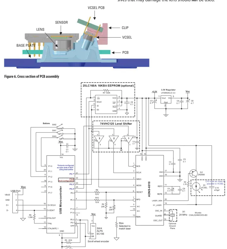
For improved electrostatic discharge performance, typical creepage and clearance distance are shown in the table below. Assumption: base plate construction as per the Avago Technologies supplied IGES file and ADNS- 6130-001 trim lens (or ADNS-6120 round lens).
Figure 6. Cross section of PCB assembly LENS
BASE PLATE
SENSOR
VCSEL PCB
VCSEL
PCB CLIP
Figure 7. Schematic Diagram for 3-Button Scroll Wheel USB PS/2 Mouse
Typical Distance Millimeters Creepage 12.0 Clearance 2.1
The lens flange can be sealed (i.e. glued) to the base plate. Note that the lens material is polycarbonate and therefore, cyanoacrylate based adhesives or other adhe- sives that may damage the lens should NOT be used.
USB Microcontroller
14
5
Vcc
9 GND 16
15
11Vreg 19
17
GND
12 13XTALOUT 20
*Outputs configured as open drain if NOT using level shifter
D1 VCSEL P0 .5*
P0 .4*
P0 .7*
P 0.6
P1.4 P0.2
P0.0 P0.3
P1.5
VPP
R4 20 K Vcc
P1.0 P1.1 P1.2 P1.3 P1.6 P1.7
P0.1
R3 20 K
ADNS-6010
Vcc
QA QB
Rbin Selected to match laser
RBIN
24 MOSI
23 21 SCLK
22 MISO
R2 20K
NCS
3 RESET
4 NPD
R1 20K R9 10 K R10 10 K
24 MHz OSC_OUT
OSC_IN GUARD
X1 REFC
REFB
C9 0.1 C8
2.2
LASER _NEN XY_LASER
Q 2 2N3906 C2
0. 1 C3 0.1
GND GND VDD3 VDD3
Vout Vin Gnd +3.3V
C7 4.7
C4 0.1
C6 4.7 1
2 3 LP2950ACZ-3.3 Vcc 3.3V Regulator
Vcc
3
SW4 ALPS EC10E
Scroll wheel encoder __
CS SCLK SI S0
VCC ___
____WP HLD GND 1
6 5 2
8 3 7 4 R7 100K
C5 0.1
N/ C D-/SDAT N/ C
D+/SCLK
XTALIN/P2.1 6
8
1 2 3 4
Vcc
VBUS
D+
D- USB Port
R5 1.30K
C1 0.1 Buttons
SW2 SW1 SW3
middle right
left
25LC160A 16KBit EEPROM (optional )
7
18 1 2 10
1 2
R6 2.7K
C10 470pF
Murata CSALS24MOX53-B0
Optional Ground Plane 6
13 9 7
15 4 1
5
19
12 11
20 3
2
10 14
8 17 16 18
3 7
C2 0. 1 1 2 2 5
6 3
9
8
74VHC125 Level Shifter
14
4 1
10
Hi-Z Configuration C10 to be as close as
possible to VCSEL
16
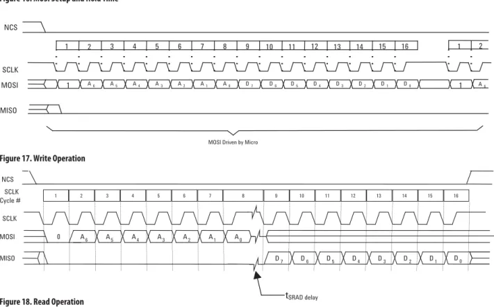
Figure 17. Write Operation Figure 16. MOSI Setup and Hold Time
A6 A5 A4 A3 A2 A1 A0 D7 D6 D5 D4 D3 D2 D1 D0
15
7 8 9 10 11 12 13 14 16
2 3 4 5 6
1 SCLK
MOSI
MOSI Driven by Micro
1
1 1
A6
2 NCS
MISO
Write Operation
Write operation, defined as data going from the micro- controller to the ADNS-6010, is always initiated by the micro-controller and consists of two bytes. The first byte contains the address (seven bits) and has a “1” as its MSB to indicate data direction. The second byte contains the data. The ADNS-6010 reads MOSI on rising edges of SCLK.
SCLK
MOSI
tsetup , MOSI
Hold,MOSI
t
Read Operation
A read operation, defined as data going from the ADNS- 6010 to the micro-controller, is always initiated by the micro-controller and consists of two bytes. The first byte contains the address, is sent by the micro-controller over
MOSI, and has a “0” as its MSB to indicate data direction.The second byte contains the data and is driven by the ADNS-6010 over MISO. The sensor outputs MISO bits on falling edges of SCLK and samples MOSI bits on every ris- ing edge of SCLK.
NOTE: The 250 ns minimum high state of SCLK is also the
minimum MISO data hold time of the ADNS-6010. Since the falling edge of SCLK is actually the start of the next read or write command, the ADNS-6010 will hold the state of data on MISO until the falling edge of SCLK.
Figure 18. Read Operation
1 2 3 4 5 6 7 8
SCLK Cycle # SCLK
MOSI 0 A6 A5 A4 A3 A2 A1 A0
9 10 11 12 13 14 15 16
MISO D7 D6 D5 D4 D3 D2 D1 D0
NCS
tSRAD delay
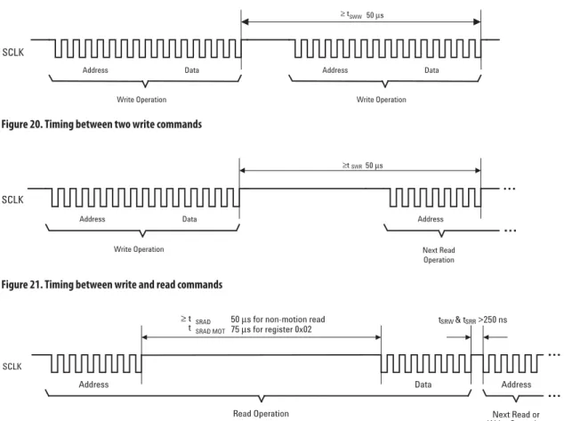
Figure 20. Timing between two write commands
Figure 21. Timing between write and read commands Figure 19. MISO Delay and Hold Time
SCLK
MISO D0
t tDLY-MISO
HOLD-MISO
Figure 22. Timing between read and either write or subsequent read commands SCLK
Address Data
≥ tSWW 50 μs
Write Operation
Address Data
Write Operation
Address Data
Write Operation
Address
Next Read Operation
≥tSWR 50 μs SCLK
Next Read or Write Operation Data
SRAD 50 μs for non-motion read
SRAD MOT 75 μs for register 0x02
Read Operation
Address tSRW & tSRR >250 ns
Address SCLK
≥ t t
The falling edge of SCLK for the first address bit of either the read or write command must be at least 250 ns after the last SCLK rising edge of the last data bit of the previ- ous read operation. In addition, during a read operation SCLK should be delayed after the last address data bit to ensure that the ADNS-6010 has time to prepare the requested data.
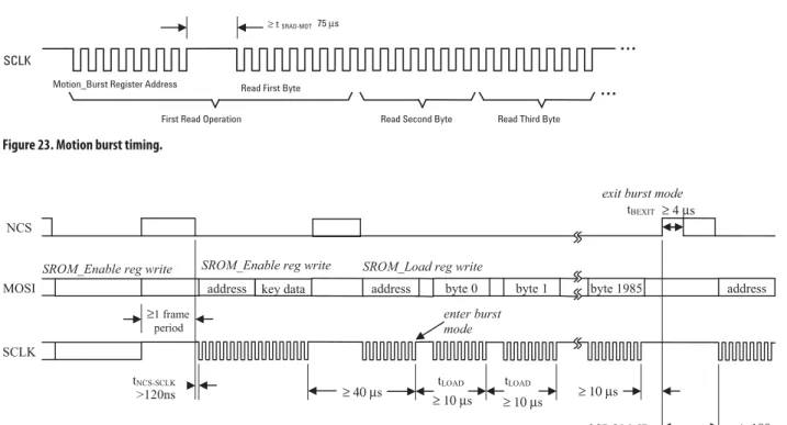
Burst Mode Operation
Burst mode is a special serial port operation mode which may be used to reduce the serial transaction time for three predefined operations: motion read and PROM download and frame capture. The speed improvement is achieved by continuous data clocking to or from multiple registers without the need to specify the register address, and by not requiring the normal delay period between data bytes.
Required timing between Read and Write Commands (tsxx)
There are minimum timing requirements between read and write commands on the serial port.
If the rising edge of the SCLK for the last data bit of the second write command occurs before the 50 microsec- ond required delay, then the first write command may not complete correctly.
If the rising edge of SCLK for the last address bit of
the read command occurs before the 50 microsecond
required delay, the write command may not complete
correctly.
18
4. Write 0x18 to register 0x14 (SROM_Enable register) 5. Begin burst mode write of data file to register 0x60
(SROM_Load register)
After the first data byte is complete, the PROM or micro- controller must write subsequent bytes by presenting the data on the MOSI line and driving SCLK at the normal rate. A delay of at least t
LOADmust exist between data bytes as shown. After the download is complete, the micro-controller must raise the NCS line for at least t
BEXITto terminate burst mode. The serial port is not available for use until it is reset with NCS, even for a second burst transmission.
Avago Technologies recommends reading the SROM_ID register to verify that the download was successful. In addition, a self-test may be executed, which performs a CRC on the SROM contents and reports the results in a register. The test is initiated by writing a particular value to the SROM_Enable register; the result is placed in the Data_Out register. See those register descriptions for more details.
Avago Technologies provides the data file for download;
the file size is 1986 data bytes. The chip will ignore any additional bytes written to the SROM_Load register after the SROM file.
Figure 23. Motion burst timing.
Figure 24. PROM Download Burst Mode
Motion_Burst Register Address Read First Byte
First Read Operation Read Second Byte
≥ tSRAD-MOT
Read Third Byte 75 μs
SCLK
NCS
address key data address byte 0 MOSI
SCLK
tNCS-SCLK
SROM_Enable reg write SROM_Load reg write
exit burst mode
enter burst mode
≥ 4 μs
tLOAD
tLOAD
byte 1 byte 1985 tBEXIT
>120ns
address
soonest to read SROM_ID SROM_Enable reg write
≥1 frame period
≥ 10μs ≥ 10μs ≥ 10μs
≥ 100μs
≥ 40μs
Motion Read
Reading the Motion_Burst register activates this mode.
The ADNS-6010 will respond with the contents of the Motion, Delta_X, Delta_Y, SQUAL, Shutter_Upper, Shut- ter_Lower, and Maximum_Pixel registers in that order.
After sending the register address, the micro-control- ler must wait t
SRAD-MOTand then begin reading data.
All 64 data bits can be read with no delay between bytes by driving SCLK at the normal rate. The data are latched into the output buffer after the last address bit is received. After the burst transmission is complete, the micro-controller must raise the NCS line for at least t
BEXITto terminate burst mode. The serial port is not available for use until it is reset with NCS, even for a second burst transmission.
PROM Download
This function is used to load the Avago Technologies- supplied firmware file contents into the ADNS-6010. The firmware file is an ASCII text file with each 2-character byte on a single line.
The following steps activate this mode:
1. Perform hardware reset by toggling the RESET pin
2. Write 0x1D to register 0x14 (SROM_Enable register)
3. Wait at least 1 frame period
Registers
The ADNS-6010 registers are accessible via the serial port. The registers are used to read motion data and status as well as to set the device configuration.
Address Register Read/Write Default Value
0x00 Product_ID R 0x1C
0x01 Revision_ID R 0x20
0x02 Motion R 0x20
0x03 Delta_X R 0x00
0x04 Delta_Y R 0x00
0x05 SQUAL R 0x00
0x06 Pixel_Sum R 0x00
0x07 Maximum_Pixel R 0x00
0x08 Reserved
0x09 Reserved
0x0a Configuration_bits R/W 0x49
0x0b Extended_Config R/W 0x08
0x0c Data_Out_Lower R Any
0x0d Data_Out_Upper R Any
0x0e Shutter_Lower R 0x85
0x0f Shutter_Upper R 0x00
0x10 Frame_Period_Lower R Any
0x11 Frame_Period_Upper R Any
0x12 Motion_Clear W Any
0x13 Frame_Capture R/W 0x00
0x14 SROM_Enable W 0x00
0x15 Reserved
0x16 Configuration II R/W 0x34
0x17 Reserved
0x18 Reserved
0x19 Frame_Period_Max_Bound Lower R/W 0x90
0x1a Frame_Period_Max_Bound_Upper R/W 0x65
0x1b Frame_Period_Min_Bound_Lower R/W 0x7E
0x1c Frame_Period_Min_Bound_Upper R/W 0x0E
0x1d Shutter_Max_Bound_Lower R/W 0x20
0x1e Shutter_Max_Bound_Upper R/W 0x4E
0x1f SROM_ID R Version dependent
0x20-0x2b Reserved
0x2c LP_CFG0 R/W 0x7F
0x2d LP_CFG1 R/W 0x80
0x2e-0x3c Reserved
0x3d Observation R/W 0x00
0x3e Reserved
0x3f Inverse Product ID R 0xE3
0x40 Pixel_Burst R 0x00
0x50 Motion_Burst R 0x00
0x60 SROM_Load W Any
25
Delta_X Address: 0x03
Access: Read Default Value: 0x00
Bit 7 6 5 4 3 2 1 0
Field X
7X
6X
5X
4X
3X
2X
1X
0Data Type: Eight bit 2’s complement number.
USAGE: X movement is counts since last report. Absolute value is determined by resolution. Reading clears the reg- ister.
00 01 02 7E 7F
+127 +126
+1 +2
FF FE 81
80
0 -1 -2 -127
Motion -128
Delta_X
Delta_Y Address: 0x04
Access: Read Default Value: 0x00
Bit 7 6 5 4 3 2 1 0
Field Y
7Y
6Y
5Y
4Y
3Y
2Y
1Y
0Data Type: Eight bit 2’s complement number.
USAGE: Y movement is counts since last report. Absolute value is determined by resolution. Reading clears the reg- ister.
00 01 02 7E 7F
+127 +126
+1 +2
FF FE 81
80
0 -1 -2 -127
Motion -128
Delta_Y
For product information and a complete list of distributors, please go to our web site: www.avagotech.com Avago, Avago Technologies, and the A logo are trademarks of Avago Technologies in the United States and other countries.
Data subject to change. Copyright © 2005-2009 Avago Technologies. All rights reserved.
AV02-1410EN - December 4, 2009
SROM_Load Address: 0x 60
Access: Write Default Value: N/A
Bit 7 6 5 4 3 2 1 0
Field SL
7SL
6SL
5SL
4SL
3SL
2SL
1SL
0Data Type: Eight bit unsigned integer
USAGE: The SROM_Load register is used for high-speed programming of the ADNS-6010 from an external PROM or microcontroller. See the Synchronous Serial Port section for use details.
Motion_Burst Address: 0x50
Access: Read Default Value: 0x00
Bit 7 6 5 4 3 2 1 0
Field MB
7MB
6MB
5MB
4MB
3MB
2MB
1MB
0Data Type: Various, depending on data
USAGE: The Motion_Burst register is used for high-speed access to the Motion, Delta_X, Delta_Y, SQUAL, Shutter_Up- per, Shutter_Lower, and Maximum_Pixel registers. See the Synchronous Serial Port section for use details.
Pixel_Burst Address: 0x40
Access: Read Default Value: 0x00
Bit 7 6 5 4 3 2 1 0
Field PB
7PB
6PB
5PB
4PB
3PB
2PB
1PB
0Data Type: Eight bit unsigned integer
USAGE: The Pixel_Burst register is used for high-speed access to all the pixel values from one and 2/3 complete frame.
See the Synchronous Serial Port section for use details.
InvenSense Inc.
1197 Borregas Ave, Sunnyvale, CA 94089 U.S.A.
Tel: +1 (408) 988-7339 Fax: +1 (408) 988-8104 Website: www.invensense.com
Document Number: PS-MPU-6000A-00 Revision: 3.3
Release Date: 5/16/2012
1 of 54
MPU-6000 and MPU-6050 Product Specification
Revision 3.3
MPU-6000/MPU-6050 Product Specification
Document Number: PS-MPU-6000A-00 Revision: 3.3
Release Date: 5/16/2012
18 of 54 6.7 I2C Timing Characterization
Typical Operating Circuit of Section 7.2, VDD = 2.375V-3.46V, VLOGIC (MPU-6050 only) = 1.8V±5% or VDD, TA = 25°C
Parameters Conditions Min Typical Max Units Notes
I2C TIMING I2C FAST-MODE
fSCL, SCL Clock Frequency 400 kHz
tHD.STA, (Repeated) START Condition Hold Time
0.6 µs
tLOW, SCL Low Period 1.3 µs
tHIGH, SCL High Period 0.6 µs
tSU.STA, Repeated START Condition Setup Time
0.6 µs
tHD.DAT, SDA Data Hold Time 0 µs
tSU.DAT, SDA Data Setup Time 100 ns
tr, SDA and SCL Rise Time Cb bus cap. from 10 to 400pF 20+0.1Cb 300 ns tf, SDA and SCL Fall Time Cb bus cap. from 10 to 400pF 20+0.1Cb 300 ns
tSU.STO, STOP Condition Setup Time 0.6 µs
tBUF, Bus Free Time Between STOP and START Condition
1.3 µs
Cb, Capacitive Load for each Bus Line < 400 pF
tVD.DAT, Data Valid Time 0.9 µs
tVD.ACK, Data Valid Acknowledge Time 0.9 µs
Note: Timing Characteristics apply to both Primary and Auxiliary I2C Bus
I2C Bus Timing Diagram
MPU-6000/MPU-6050 Product Specification
Document Number: PS-MPU-6000A-00 Revision: 3.3
Release Date: 5/16/2012
24 of 54 7.5 Block Diagram
CLOCK
MPU-60X0
Charge Pump
(/CS) AD0 / (SDO) SCL / (SCLK) SDA / (SDI)
Temp Sensor ADC Z Gyro ADC
ADC Y Gyro
Digital Motion Processor
(DMP)
FSYNC 22
1
8 9 23 24
11 Slave I2C and
SPI Serial Interface
Master I2C Serial Interface Clock
CPOUT
Serial Interface
Bypass Mux
7 6
AUX_CL AUX_DA 12 INT
20
Factory Calibration
Interrupt Status Register
VDD
Bias & LDO
GND REGOUT
13 18 10
Note: Pin names in round brackets ( ) apply only to MPU-6000 Pin names in square brackets [ ] apply only to MPU-6050
Z Accel Y Accel
X Accel ADC
ADC
ADC CLKIN
CLKOUT
ADC X Gyro
Signal Conditioning
FIFO
Config Registers
Sensor Registers Self
test
[VLOGIC]
8 Self
test Self test
Self test Self test Self test
7.6 Overview
The MPU-60X0 is comprised of the following key blocks and functions:
Three-axis MEMS rate gyroscope sensor with 16-bit ADCs and signal conditioning
Three-axis MEMS accelerometer sensor with 16-bit ADCs and signal conditioning
Digital Motion Processor (DMP) engine
Primary I2C and SPI (MPU-6000 only) serial communications interfaces
Auxiliary I2C serial interface for 3rd party magnetometer & other sensors
Clocking
Sensor Data Registers
FIFO
Interrupts
Digital-Output Temperature Sensor
Gyroscope & Accelerometer Self-test
Bias and LDO
Charge Pump
MPU-6000/MPU-6050 Product Specification
Document Number: PS-MPU-6000A-00 Revision: 3.3
Release Date: 5/16/2012
28 of 54
7.13 MPU-60X0 Solution for 9-axis Sensor Fusion Using I2C Interface
In the figure below, the system processor is an I2C master to the MPU-60X0. In addition, the MPU-60X0 is an I2C master to the optional external compass sensor. The MPU-60X0 has limited capabilities as an I2C Master, and depends on the system processor to manage the initial configuration of any auxiliary sensors.
The MPU-60X0 has an interface bypass multiplexer, which connects the system processor I2C bus pins 23 and 24 (SDA and SCL) directly to the auxiliary sensor I2C bus pins 6 and 7 (AUX_DA and AUX_CL).
Once the auxiliary sensors have been configured by the system processor, the interface bypass multiplexer should be disabled so that the MPU-60X0 auxiliary I2C master can take control of the sensor I2C bus and gather data from the auxiliary sensors.
For further information regarding I2C master control, please refer to Section 10.
MPU-60X0
AD0/SDOSCL/SCLK SDA/SDI
Digital Motion Processor
(DMP)
9 23 24
Sensor Master I2C
Serial Interface
7 6
AUX_CL AUX_DA Interrupt
Status Register
12 INT
VDD
Bias & LDO
GND REGOUT
13 18 10
FIFO
Config Register
Sensor Register
Factory Calibration
8 /CS
Slave I2C or SPI Serial Interface
Compass SCL
SDA
System Processor
Interface Bypass
Mux
SCL SDA VDD
VDD or GND
I2C Processor Bus: for reading all sensor data from MPU and for configuring external sensors (i.e.
compass in this example)
Interface bypass mux allows direct configuration of compass by system processor
Optional Sensor I2C Bus: for
configuring and reading from external sensors
InvenSense Inc.
1197 Borregas Ave, Sunnyvale, CA 94089 U.S.A.
Tel: +1 (408) 988-7339 Fax: +1 (408) 988-8104 Website: www.invensense.com
Document Number: RM-MPU-6000A-00 Revision: 4.0
Release Date: 03/09/2012
CONFIDENTIAL & PROPRIETARY
1 of 47
MPU-6000 and MPU-6050
Register Map and Descriptions
Revision 4.0
MPU-6000/MPU-6050 Register Map and Descriptions
Document Number: RM-MPU-6000A-00 Revision: 4.0
Release Date: 03/09/2012
CONFIDENTIAL & PROPRIETARY
6 of 47
3 Register Map
The register map for the MPU-60X0 is listed below.
Addr (Hex)
Addr
(Dec.) Register Name Serial
I/F Bit7 Bit6 Bit5 Bit4 Bit3 Bit2 Bit1 Bit0
0D 13 SELF_TEST_X R/W XA_TEST[4-2] XG_TEST[4-0]
0E 14 SELF_TEST_Y R/W YA_TEST[4-2] YG_TEST[4-0]
0F 15 SELF_TEST_Z R/W ZA_TEST[4-2] ZG_TEST[4-0]
10 16 SELF_TEST_A R/W RESERVED XA_TEST[1-0] YA_TEST[1-0] ZA_TEST[1-0]
19 25 SMPLRT_DIV R/W SMPLRT_DIV[7:0]
1A 26 CONFIG R/W - - EXT_SYNC_SET[2:0] DLPF_CFG[2:0]
1B 27 GYRO_CONFIG R/W - - - FS_SEL [1:0] - - -
1C 28 ACCEL_CONFIG R/W XA_ST YA_ST ZA_ST AFS_SEL[1:0]
1F 31 MOT_THR R/W MOT_THR[7:0]
23 35 FIFO_EN R/W TEMP
_FIFO_EN
XG _FIFO_EN
YG _FIFO_EN
ZG _FIFO_EN
ACCEL _FIFO_EN
SLV2 _FIFO_EN
SLV1 _FIFO_EN
SLV0 _FIFO_EN
24 36 I2C_MST_CTRL R/W MULT
_MST_EN
WAIT _FOR_ES
SLV_3 _FIFO_EN
I2C_MST
_P_NSR I2C_MST_CLK[3:0]
25 37 I2C_SLV0_ADDR R/W I2C_SLV0
_RW I2C_SLV0_ADDR[6:0]
26 38 I2C_SLV0_REG R/W I2C_SLV0_REG[7:0]
27 39 I2C_SLV0_CTRL R/W I2C_SLV0
_EN
I2C_SLV0 _BYTE_SW
I2C_SLV0 _REG_DIS
I2C_SLV0
_GRP I2C_SLV0_LEN[3:0]
28 40 I2C_SLV1_ADDR R/W I2C_SLV1
_RW I2C_SLV1_ADDR[6:0]
29 41 I2C_SLV1_REG R/W I2C_SLV1_REG[7:0]
2A 42 I2C_SLV1_CTRL R/W I2C_SLV1 _EN
I2C_SLV1 _BYTE_SW
I2C_SLV1 _REG_DIS
I2C_SLV1
_GRP I2C_SLV1_LEN[3:0]
2B 43 I2C_SLV2_ADDR R/W I2C_SLV2
_RW I2C_SLV2_ADDR[6:0]
2C 44 I2C_SLV2_REG R/W I2C_SLV2_REG[7:0]
2D 45 I2C_SLV2_CTRL R/W I2C_SLV2
_EN
I2C_SLV2 _BYTE_SW
I2C_SLV2 _REG_DIS
I2C_SLV2
_GRP I2C_SLV2_LEN[3:0]
2E 46 I2C_SLV3_ADDR R/W I2C_SLV3
_RW I2C_SLV3_ADDR[6:0]
2F 47 I2C_SLV3_REG R/W I2C_SLV3_REG[7:0]
30 48 I2C_SLV3_CTRL R/W I2C_SLV3
_EN
I2C_SLV3 _BYTE_SW
I2C_SLV3 _REG_DIS
I2C_SLV3
_GRP I2C_SLV3_LEN[3:0]
31 49 I2C_SLV4_ADDR R/W I2C_SLV4
_RW I2C_SLV4_ADDR[6:0]
32 50 I2C_SLV4_REG R/W I2C_SLV4_REG[7:0]
33 51 I2C_SLV4_DO R/W I2C_SLV4_DO[7:0]
34 52 I2C_SLV4_CTRL R/W I2C_SLV4
_EN
I2C_SLV4 _INT_EN
I2C_SLV4
_REG_DIS I2C_MST_DLY[4:0]
35 53 I2C_SLV4_DI R I2C_SLV4_DI[7:0]
36 54 I2C_MST_STATUS R PASS_
THROUGH
I2C_SLV4 _DONE
I2C_LOST _ARB
I2C_SLV4 _NACK
I2C_SLV3 _NACK
I2C_SLV2 _NACK
I2C_SLV1 _NACK
I2C_SLV0 _NACK
37 55 INT_PIN_CFG R/W INT_LEVEL INT_OPEN LATCH
_INT_EN
INT_RD _CLEAR
FSYNC_
INT_LEVEL
FSYNC _INT_EN
I2C _BYPASS
_EN
-
38 56 INT_ENABLE R/W - MOT_EN -
FIFO _OFLOW
_EN
I2C_MST
_INT_EN - - DATA
_RDY_EN
MPU-6000/MPU-6050 Register Map and Descriptions
Document Number: RM-MPU-6000A-00 Revision: 4.0
Release Date: 03/09/2012
CONFIDENTIAL & PROPRIETARY
7 of 47
Addr (Hex)
Addr
(Dec.) Register Name Serial
I/F Bit7 Bit6 Bit5 Bit4 Bit3 Bit2 Bit1 Bit0
3A 58 INT_STATUS R - MOT_INT -
FIFO _OFLOW
_INT
I2C_MST
_INT - - DATA
_RDY_INT
3B 59 ACCEL_XOUT_H R ACCEL_XOUT[15:8]
3C 60 ACCEL_XOUT_L R ACCEL_XOUT[7:0]
3D 61 ACCEL_YOUT_H R ACCEL_YOUT[15:8]
3E 62 ACCEL_YOUT_L R ACCEL_YOUT[7:0]
3F 63 ACCEL_ZOUT_H R ACCEL_ZOUT[15:8]
40 64 ACCEL_ZOUT_L R ACCEL_ZOUT[7:0]
41 65 TEMP_OUT_H R TEMP_OUT[15:8]
42 66 TEMP_OUT_L R TEMP_OUT[7:0]
43 67 GYRO_XOUT_H R GYRO_XOUT[15:8]
44 68 GYRO_XOUT_L R GYRO_XOUT[7:0]
45 69 GYRO_YOUT_H R GYRO_YOUT[15:8]
46 70 GYRO_YOUT_L R GYRO_YOUT[7:0]
47 71 GYRO_ZOUT_H R GYRO_ZOUT[15:8]
48 72 GYRO_ZOUT_L R GYRO_ZOUT[7:0]
49 73 EXT_SENS_DATA_00 R EXT_SENS_DATA_00[7:0]
4A 74 EXT_SENS_DATA_01 R EXT_SENS_DATA_01[7:0]
4B 75 EXT_SENS_DATA_02 R EXT_SENS_DATA_02[7:0]
4C 76 EXT_SENS_DATA_03 R EXT_SENS_DATA_03[7:0]
4D 77 EXT_SENS_DATA_04 R EXT_SENS_DATA_04[7:0]
4E 78 EXT_SENS_DATA_05 R EXT_SENS_DATA_05[7:0]
4F 79 EXT_SENS_DATA_06 R EXT_SENS_DATA_06[7:0]
50 80 EXT_SENS_DATA_07 R EXT_SENS_DATA_07[7:0]
51 81 EXT_SENS_DATA_08 R EXT_SENS_DATA_08[7:0]
52 82 EXT_SENS_DATA_09 R EXT_SENS_DATA_09[7:0]
53 83 EXT_SENS_DATA_10 R EXT_SENS_DATA_10[7:0]
54 84 EXT_SENS_DATA_11 R EXT_SENS_DATA_11[7:0]
55 85 EXT_SENS_DATA_12 R EXT_SENS_DATA_12[7:0]
56 86 EXT_SENS_DATA_13 R EXT_SENS_DATA_13[7:0]
57 87 EXT_SENS_DATA_14 R EXT_SENS_DATA_14[7:0]
58 88 EXT_SENS_DATA_15 R EXT_SENS_DATA_15[7:0]
59 89 EXT_SENS_DATA_16 R EXT_SENS_DATA_16[7:0]
5A 90 EXT_SENS_DATA_17 R EXT_SENS_DATA_17[7:0]
5B 91 EXT_SENS_DATA_18 R EXT_SENS_DATA_18[7:0]
5C 92 EXT_SENS_DATA_19 R EXT_SENS_DATA_19[7:0]
5D 93 EXT_SENS_DATA_20 R EXT_SENS_DATA_20[7:0]
5E 94 EXT_SENS_DATA_21 R EXT_SENS_DATA_21[7:0]
5F 95 EXT_SENS_DATA_22 R EXT_SENS_DATA_22[7:0]
60 96 EXT_SENS_DATA_23 R EXT_SENS_DATA_23[7:0]
63 99 I2C_SLV0_DO R/W I2C_SLV0_DO[7:0]
64 100 I2C_SLV1_DO R/W I2C_SLV1_DO[7:0]
MPU-6000/MPU-6050 Register Map and Descriptions
Document Number: RM-MPU-6000A-00 Revision: 4.0
Release Date: 03/09/2012
CONFIDENTIAL & PROPRIETARY
8 of 47
Addr (Hex)
Addr
(Dec.) Register Name Serial
I/F Bit7 Bit6 Bit5 Bit4 Bit3 Bit2 Bit1 Bit0
65 101 I2C_SLV2_DO R/W I2C_SLV2_DO[7:0]
66 102 I2C_SLV3_DO R/W I2C_SLV3_DO[7:0]
67 103 I2C_MST_DELAY_CT
RL R/W DELAY_ES
_SHADOW - - I2C_SLV4
_DLY_EN
I2C_SLV3 _DLY_EN
I2C_SLV2 _DLY_EN
I2C_SLV1 _DLY_EN
I2C_SLV0 _DLY_EN 68 104 SIGNAL_PATH_RES
ET R/W - - - - - GYRO
_RESET
ACCEL _RESET
TEMP _RESET
69 105 MOT_DETECT_CTRL R/W - - ACCEL_ON_DELAY[1:0] - -
6A 106 USER_CTRL R/W - FIFO_EN I2C_MST
_EN
I2C_IF
_DIS - FIFO
_RESET
I2C_MST _RESET
SIG_COND _RESET
6B 107 PWR_MGMT_1 R/W DEVICE
_RESET SLEEP CYCLE - TEMP_DIS CLKSEL[2:0]
6C 108 PWR_MGMT_2 R/W LP_WAKE_CTRL[1:0] STBY_XA STBY_YA STBY_ZA STBY_XG STBY_YG STBY_ZG
72 114 FIFO_COUNTH R/W FIFO_COUNT[15:8]
73 115 FIFO_COUNTL R/W FIFO_COUNT[7:0]
74 116 FIFO_R_W R/W FIFO_DATA[7:0]
75 117 WHO_AM_I R - WHO_AM_I[6:1] -
Note: Register Names ending in _H and _L contain the high and low bytes, respectively, of an internal register value.
In the detailed register tables that follow, register names are in capital letters, while register values are in capital letters and italicized. For example, the ACCEL_XOUT_H register (Register 59) contains the 8 most significant bits, ACCEL_XOUT[15:8], of the 16-bit X-Axis accelerometer measurement, ACCEL_XOUT.
The reset value is 0x00 for all registers other than the registers below.
•
Register 107: 0x40.
•
Register 117: 0x68.
MPU-6000/MPU-6050 Register Map and Descriptions
Document Number: RM-MPU-6000A-00 Revision: 4.0
Release Date: 03/09/2012
CONFIDENTIAL & PROPRIETARY
14 of 47
4.4 Register 27 – Gyroscope Configuration GYRO_CONFIG
Type: Read/Write
Register (Hex)
Register
(Decimal) Bit7 Bit6 Bit5 Bit4 Bit3 Bit2 Bit1 Bit0
1B 27 XG_ST YG_ST ZG_ST FS_SEL[1:0] - - -
This register is used to trigger gyroscope self-test and configure the gyroscopes’ full scale range.
Description:
Gyroscope self-test permits users to test the mechanical and electrical portions of the gyroscope. The self-test for each gyroscope axis can be activated by controlling the XG_ST,
YG_ST, and ZG_ST bits of this register. Self-test for each axis may be performed independentlyor all at the same time.
When self-test is activated, the on-board electronics will actuate the appropriate sensor. This actuation will move the sensor’s proof masses over a distance equivalent to a pre-defined Coriolis force. This proof mass displacement results in a change in the sensor output, which is reflected in the output signal. The output signal is used to observe the self-test response.
The self-test response is defined as follows:
Self-test response = Sensor output with self-test enabled – Sensor output without self- test enabled
The self-test limits for each gyroscope axis is provided in the electrical characteristics tables of the MPU-6000/MPU-6050 Product Specification document. When the value of the self-test response is within the min/max limits of the product specification, the part has passed self test.
When the self-test response exceeds the min/max values specified in the document, the part is deemed to have failed self-test.
FS_SEL selects the full scale range of the gyroscope outputs according to the following table.
FS_SEL Full Scale Range
0 ± 250 °/s
1 ± 500 °/s
2 ± 1000 °/s
3 ± 2000 °/s
Bits 2 through 0 are reserved.
XG_ST
Setting this bit causes the X axis gyroscope to perform self test.
Parameters:
YG_ST
Setting this bit causes the Y axis gyroscope to perform self test.
ZG_ST
Setting this bit causes the Z axis gyroscope to perform self test.
FS_SEL
2-bit unsigned value. Selects the full scale range of gyroscopes.
MPU-6000/MPU-6050 Register Map and Descriptions
Document Number: RM-MPU-6000A-00 Revision: 4.0
Release Date: 03/09/2012
CONFIDENTIAL & PROPRIETARY
32 of 47
4.20 Registers 67 to 72 – Gyroscope Measurements
GYRO_XOUT_H, GYRO_XOUT_L, GYRO_YOUT_H, GYRO_YOUT_L, GYRO_ZOUT_H, and GYRO_ZOUT_L
Type: Read Only
Register (Hex)
Register
(Decimal) Bit7 Bit6 Bit5 Bit4 Bit3 Bit2 Bit1 Bit0
43 67 GYRO_XOUT[15:8]
44 68 GYRO_XOUT[7:0]
45 69 GYRO_YOUT[15:8]
46 70 GYRO_YOUT[7:0]
47 71 GYRO_ZOUT[15:8]
48 72 GYRO_ZOUT[7:0]
These registers store the most recent gyroscope measurements.
Description:
Gyroscope measurements are written to these registers at the Sample Rate as defined in Register 25.
These gyroscope measurement registers, along with the accelerometer measurement registers, temperature measurement registers, and external sensor data registers, are composed of two sets of registers: an internal register set and a user-facing read register set.
The data within the gyroscope sensors’ internal register set is always updated at the Sample Rate.
Meanwhile, the user-facing read register set duplicates the internal register set’s data values whenever the serial interface is idle. This guarantees that a burst read of sensor registers will read measurements from the same sampling instant. Note that if burst reads are not used, the user is responsible for ensuring a set of single byte reads correspond to a single sampling instant by checking the Data Ready interrupt.
Each 16-bit gyroscope measurement has a full scale defined in FS_SEL (Register 27). For each full scale setting, the gyroscopes’ sensitivity per LSB in GYRO_xOUT is shown in the table below:
FS_SEL Full Scale Range LSB Sensitivity
0 ± 250 °/s 131 LSB/°/s
1 ± 500 °/s 65.5 LSB/°/s 2 ± 1000 °/s 32.8 LSB/°/s 3 ± 2000 °/s 16.4 LSB/°/s
GYRO_XOUT 16-bit 2’s complement value.
Parameters:
Stores the most recent X axis gyroscope measurement.
GYRO_YOUT 16-bit 2’s complement value.
Stores the most recent Y axis gyroscope measurement.
GYRO_ZOUT
16-bit 2’s complement value.
Stores the most recent Z axis gyroscope measurement.
MPU-6000/MPU-6050 Register Map and Descriptions
Document Number: RM-MPU-6000A-00 Revision: 4.0
Release Date: 03/09/2012
CONFIDENTIAL & PROPRIETARY
46 of 47
4.34 Register 117 – Who Am I WHO_AM_I
Type: Read Only
Register (Hex)
Register
(Decimal) Bit7 Bit6 Bit5 Bit4 Bit3 Bit2 Bit1 Bit0
75 117 - WHO_AM_I[6:1] -
This register is used to verify the identity of the device. The contents of WHO_AM_I are the upper 6 bits of the MPU-60X0’s 7-bit I
2C address. The least significant bit of the MPU-60X0’s I
2C address is determined by the value of the AD0 pin. The value of the AD0 pin is not reflected in this register.
Description:
The default value of the register is 0x68.
Bits 0 and 7 are reserved. (Hard coded to 0)
WHO_AM_I