インターポレータ / Interpolator / Interpolator
MD20B
/
お買い上げいただき、ありがとうございます。
ご使用の前に、この取扱説明書を必ずお読みください。
ご使用に際しては、この取扱説明書どおりお使いください。
お読みになった後は、後日お役に立つこともございますので、必ず保管してください。
Read all the instructions in the manual carefully before use and strictly follow them.
Keep the manual for future references.
Lesen Sie die ganze Anleitung vor dem Betrieb aufmerksam durch und folgen Sie beim Betrieb des Geräts den Anweisungen. Bewahren Sie diese Bedienungsanleitung zum späteren Nachlesen griffbereit auf.
MD20B
[For U.S.A. and Canada]
THIS CLASS A DIGITAL DEVICE COMPLIES WITH PART15 OF THE FCC RULES AND THE CANADIAN ICES-003. OPERATION IS SUBJECT TO THE FOLLOWING TWO CONDITIONS.
(1) THIS DEVICE MAY NOT CAUSE HARMFUL INTERFERENCE, AND
(2) T H I S D E V I C E M U S T A C C E P T A N Y INTERFERENCE RECEIVED, INCLUDING I N T E R F E R E N C E T H A T M A Y C A U S E UNDERSIGNED OPERATION.
CET APPAREIL NUMÉRIQUE DE LA CLASSE A EST CONFORME À LA NORME NMB-003 DU CANADA.
[For the customers in Australia]
Australian EMC Notice
This product complies with the following Australian EMC standard.
AS/NZS CISPR11/2002 Emission Standard for ISM Equipment
目次
1. ご使用になる前に ... 1
1-1. 一般的な注意事項 ... 1
2. 概要 ... 2
3. 特長 ... 2
4. 仕様 ... 3
5. 使用方法 ... 9
5-1. 各部の名称 ... 9
5-2. 分解能の設定 ... 10
5-3. 出力パルス幅の設定 ... 10
5-4. 方向切替 ... 11
5-5. 原点の使用法 ... 11
5-6. ファナックNCでの原点の使用法 ... 13
5-7. 電源の供給方法 ... 14
5-8. アラーム信号 ... 14
5-9. インターポレータの取付け ... 15
6. 調整 ... 16
6-1. スケール信号調整 ... 16
6-2. 原点設定 ... 19
7. 入出力コネクタ仕様 ... 22
7-1. ヘッドケーブルコネクタ ... 22
7-2. 原点コネクタ ... 23
7-3. 出力コネクタ ... 23
8. 外形寸法図 ... 25
MD20B
1. ご使用になる前に
1-1. 一般的な注意事項
以下は当社製品を正しくお使いいただくための一般的注意 事項ですので、個々の詳細な取扱上の注意は、本取扱説明 書に記述された諸事項および注意をうながしている説明事 項に従い、正しいお取扱いをいただきたくお願いいたしま す。
• 始業または操業時には、当社製品の機能および性能が正 常に作動していることを確認してからご使用ください。
• 当社製品が万一故障した場合、各種の損害を防止するた めの充分な保全対策を施してご使用ください。
• 仕様に示された規格以外での使用または改造を施された 製品については、機能および性能の保証はできませんの でご留意ください。
• 当社製品を他の機器と組合わせてご使用になる場合は、
使用条件、環境等により、その機能および性能が満足さ れない場合がありますので、充分ご検討の上ご使用くだ さい。
• 本体カバーを開けたり内部に手を差し入れたりすること は、静電気などによって内部回路が破損する恐れがあり ますのでおやめください。
• 本装置は防爆構造ではありませんので、可燃性ガスの雰 囲気中ではご使用になれません。
• 本装置は特に耐振構造になっておりませんので、衝撃の ある場所でのご使用はおやめください。
このたびは当社製品をお買い上げいただき誠にありがとう ございます。
ご使用になる前にこの説明書を最後までよくお読みくださ い。そして大切に保存してください。
MD20B
• 拡張容易なモジュラー方式
1軸筐体型ユニットの組み合わせで簡単に多軸構成が できます。
• DC5 V単電源で動作します。
• スケール信号同期型原点回路を内蔵しています。
• アラーム機能を持っています。
• 分解能、出力パルス幅を、正面のスイッチ操作により、
簡単に設定することができます。
• 信号出力は、A / B相信号、up / down信号、原点信号、
アラーム信号ともにDS34C87相当の電圧差動ラインドラ イバーを使用しています。
• スケールとの接続にD-subコネクタを使用しているの で、高密度実装に適します。
3. 特長
本インターポレータMD20シリーズは、NC装置等の機器組 込み用として設計された、ユニットタイプ1軸筐体型小型イ ンターポレータです。
MD20Bは当社スケール (別売) と接続し、A / B相出力とup / down出力を同時に出力します。
2. 概要
4. 仕様
分解能 0.1 µm, 0.2 µm, 0.5 µm, 1 µm, 2 µm, 4 µm, 2.5 µm, 5 µm, 10 µm (注1) 出力パルス幅 (Tw) 0.1 µs, 0.2 µs, 0.25 µs, 0.5 µs, 1 µs, 2 µs, 2.5 µs, 5 µs, 10 µs, 20 µs (注2) 接続可能なスケール SR721, SR721R, SR721RD, SR721RN, SR801, SR801R, SR127, SR128
接続ヘッドケーブル D-Subコネクタ付きケーブル 接続ヘッドケーブル長 最大50 m
接続スケール 使用ケーブル
SR721, SR801 MK6, MK7
SR127/128 CE11
SR721R, SR801R AK1
SR721RD
SR721RN AK3
(注2) 出力パルス幅は、本体正面のスイッチ (Tw) により切替え ることができます。10ページの5-3項を参照してくださ い。
本インターポレータのA / B出力信号は、一般のロータリー エンコーダと違い、擬似的に作っていますので、スケール 移動速度が遅い場合でもあらかじめ設定したパルス幅 (Tw) で出力されることがあります。
受信回路は、設定したパルス幅の信号を受けられるものが 必要です。
PCA PCB
設定した分解能
(注1) 分解能は、本体正面のスイッチ (RES) により切替えること ができます。10ページの5-2項を参照してください。
本インターポレータのA / B出力は、A相、B相の位相差が 設定した分解能となります。
MD20B
出力信号 注1) 移動量は約20 µs毎に検出され、この期間
(約20 µs) に動いたスケールまたはヘッド の変位量に相当するパルスとして出力さ れます。
注2) Up / Down出力は必ずUp / Downカウン ターで受信してください。片方のみの出 力でご使用になりますと正確な計測を行 なえません。
原点信号 原点信号の幅は約8 mmあり、移動時に両方向
で出力されますが、いずれか一方向のみの立 上りを原点信号としてご使用ください。
A / B相出力
Up / Down出力 (注2)
∗ PCAPCA
∗ PCBPCB
∗ PCUPCU
∗ PCDPCD
Tw
Tw Tw/2
Tw : 最小位相差
Tw : 最小繰返し周期 Tw/2 : パルス幅
8 mm PCZ
∗ PCZ
出力回路 各出力は電圧差動型ラインドライバ (DS34C87) を使用しております。したがって、受信回路には電圧差動型ライ ンレシーバ (DS34C86相当品) をご使用ください。
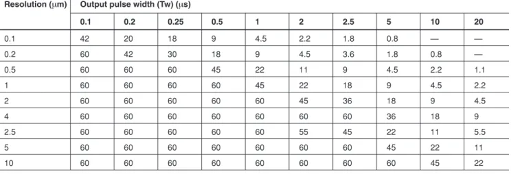
最大応答速度 最大応答速度は、分解能と出力パルス幅によって異なります。7ページの表3-1を参照してください。
外部原点回路 マグネスイッチPH100-3P (5P、10P、15P) またはPH100と発磁体PG-104が使用できます。
原点応答速度 原点の応答速度は、分解能によって異なります。8ページの表3-2を参照してください。
アラーム信号 スケールが最大応答速度を超えたとき、またはヘッドケーブル等の断線があったときに働きます。アラーム発生時 にはALARM出力がHighになり、∗ ALARM出力がLOWになります。このとき原点出力を除き、PCA、∗ PCA、
PCB、∗ PCB、PCU、∗ PCU、PCD、∗ PCD出力はすべてハイインピーダンスとなります。
アラーム解除 アラームの解除は、アラーム発生の原因をすべて取り除いたのちに、リセットをかけるか、または電源の再投入を することにより行なわれます。
また、アラーム状態であっても外部リセットがかかっていれば、アラーム信号は出力されず、ハイインピーダンス にもなりません。ただし、出力信号は停止します。
リセット 本体正面のRESETボタンを押すと、インターポレータはリセットされます。
また、外部からリセットをかける場合には、出力コネクタの20番ピンと7番 ピンを短絡してください。
外部リセット信号入力仕様 最小リセット時間: 10 ms 最大動作復帰時間: 10 ms (リセット解除後)
PCA, PCB, PCU, PCD, PCZ, ALARM
∗ PCA, ∗ PCB, ∗ PCU, ∗ PCD, ∗ PCZ, ∗ ALARM
+3.3 V
外部リセット信号入力回路
20: RES
7: 0 V +
MD20B
電源 DC +5 V (±5 %) 消費電力 MD20B 3 W (max) 使用温度範囲 0 °C〜+55 °C 保存温度範囲 –10 °C〜+75 °C 外形寸法 171 × 144 × 32 (mm) 質量 800 g
付属品 •出力コネクタ ... 1式
•連結金具 ... 3枚
•ねじ M3 × 6 ... 6本
•取付ねじ M4 × 8 ... 2本
•軸ラベル ... 1式
•取扱説明書 ... 1部
表3-1 最大応答速度
分解能 (µm) 出力パルス幅 (Tw) (µs)
0.1 0.2 0.25 0.5 1 2 2.5 5 10 20
0.1 42 20 18 9 4.5 2.2 1.8 0.8 − −
0.2 60 42 30 18 9 4.5 3.6 1.8 0.8 −
0.5 60 60 60 45 22 11 9 4.5 2.2 1.1
1 60 60 60 60 45 22 18 9 4.5 2.2
2 60 60 60 60 60 45 36 18 9 4.5
4 60 60 60 60 60 60 60 36 18 9
2.5 60 60 60 60 60 55 45 22 11 5.5
5 60 60 60 60 60 60 60 45 22 11
10 60 60 60 60 60 60 60 60 45 22
(単位: m/min)
MD20B
表3-2 原点応答速度
分解能 応答速度
0.1 µm〜10 µm 5 m/min
注) 原点の応答速度は、分解能とパルス幅で規定されたスケールの 最大応答速度を超えることはできません。(たとえば、分解能 0.5 µmでパルス幅10 µsの場合、原点の応答速度は2.2 m/min となります。)
全分解能において原点取り速度は15 m/minまで対応するこ とが可能ですが、原点通過速度が上がると速度変動の影響 で、原点出力位置は不安定になります。
5 m/min以上で使用する場合は、原点設定時と原点取得時の 送り速度を常に同じにしてください。
注意
原点の応対速度は、分解能とパルス幅で規定されたスケー ルの最大応答速度を超えることはできません。
5-1. 各部の名称
5. 使用方法
背面 側面 正面
分解能 (RES) 端子台
出力コネクタ 原点コネクタ ヘッドケーブル コネクタ
POSランプ
アラームランプ 原点ランプ
信号調整 ボリューム リセットボタン パルス幅 (Tw)
PM端子 TRIG端子 原点設定 (R.ADJ) SW
方向切替 (DIR) SW MODE SW
MD20B
5-2. 分解能の設定
本インターポレータの分解能は、本体正面のロータリース イッチRESを切替えることによって、下表のように設定す ることができます。
分解能設定表
RES 分解能 (µm)
0 ─
1 10
2 5
3 2.5
4 4
5 2
6 1
7 0.5
8 0.2
9 0.1
出荷時設定: RES = 6 (1 µm)
5-3. 出力パルス幅の設定
出力パルス幅は本体正面のロータリースイッチTwを切替え ることによって、下表のように設定することができます。
パルス幅設定表
Tw パルス幅 (µs)
0 0.25
1 0.5
2 1
3 2
4 2.5
5 5
6 10
7 20
8 0.2
9 0.1
出荷時設定: Tw = 2 (1 µs)
注) 0.1 µm分解能時はパルス幅20 µsと10 µsでは使用できませ ん。0.2 µm分解能時はパルス幅20 µsでは使用できません。
5-4. 方向切替
本体正面のDIPスイッチの切替えにより、スケールの移動方 向に対するパルス出力の極性を切替えることができます。
5-5. 原点の使用法
このインターポレータは、外部原点または原点内蔵型のス ケールを使用したとき、200 µm毎に出力されるスケールλ信 号に同期した高精度の原点信号を有効長内で1箇所出力しま す。(図5-1)
原点信号をご使用の際は、精度維持のため当社システムを ご使用ください。
また次ページに示すように、原点信号は移動時に両方向で 出力されますが、あらかじめ使用者の定めた方向に移動中 に出力される信号の立ち上がりエッジのみを原点信号とし てご使用ください。
注意
REFランプ点灯領域内で電源を投入した場合、または、リ セット操作を行なった場合、一度領域外にスケールを移動 させてから原点取り操作を行なってください。
原点取りを行なう際には、8ページ表3-2に示す最大応答速度 を超えないようにしてください。
原点内蔵スケールに外部原点を併用することはできませ ん。
いずれの場合も原点位置のずれを発生することがありま す。
MD20B 図5-1. 原点信号仕様
スケールλ信号
REFランプ (原点ゲート)
原点出力検出方向
原点出力逆方向
200 µm
約8 mm
↑このエッジを参照する。
5-6. ファナックNCでの原点の使用法
ファナックシステムと組合せるとき、NCの設定をハード、
ソフト共グリッド方式にします。
• マグネスケールを使用した場合、原点復帰モードとして グリッド方式を使用します。マグネスケールの原点位置 と、機械の原点位置は異なりますのでご注意ください。
手動連続送りモードを選択し、手動送りボタンによりリ ファレンス点に向かって送りをかけると早送り速度で移動 し、減速リミットを踏むと減速し、その後微速送り (FL速 度) になります。微速送り中に原点信号が立ち上ると、その 点からリファレンスカウンターがスタートし、一定の間隔 でグリッドを作ります。その後リミットスイッチが外れる と最初のグリッド点で機械が停止します。この停止点は、
別途NC内のグリッドシフト設定によって任意にシフトでき ます。
以上の原点復帰動作の中で重要なのは、減速ドグがONしFL 状態の間に、原点信号を立ち上げることです。この場合、
原点信号の立ち下りは全く無関係となります。
V
早送り速度 停止点
FL速度
減速ドグ
原点信号 グリッド
減速ドグのOFF点はグリッド間隔の中央近辺に来る ように設定します。
パラメータによりグリッドシフト量が設定できる。
原点信号立上り有効範囲
リファレンスカウンタの容量によって決まる幅
MD20B
電源投入時、
1) インターポレータの電源を入れる。
2) 受信装置の電源を入れる。
または、
1) インターポレータ、受信装置の電源を同時に入れる。
2) 受信装置の初期設定を行なう。
電源切断時、
1) 受信装置の電源を切る。
2) インターポレータの電源を切る。
5-8. アラーム信号
アラーム信号は、スケールが最大応答速度を超えた場合、
または、ヘッドケーブルが断線した場合に出力されます。
このときは、スケール信号が出力停止し、ハイインピーダ ンス状態となります。
そのまま機械を動かしますと、事故に至ることが考えられ ます。アラーム信号が出力されたときは、機械が停止する などの安全機能を設けてください。
なお、アラーム信号は、マグネスケールシステムの全ての 異常を検出しているものではありません。オーバーラン防 止等充分な保全対策を設けてください。
5-7. 電源の供給方法
端子台から電源供給を行なったとき、出力コネクタに +5 Vが出力されますが、誤動作防止のため使用しない でください。
また、本インターポレータは、出力コネクタより電源供給 することも可能です。信号受信装置に600 mA以上 (1軸当り) の容量をもつ+5 V電源があれば、出力コネクタ (4、5、6番 ピン) より電源供給ができます。
この場合は、端子台からの電源供給はしないでください。
本インターポレータは電源投入後、最大1秒間は信号出力を 停止します。また、電源切断時に過渡的に信号出力をする ことがあります。
システム内で特にデータをバックアップするときなどの場 合、誤動作防止のために電源投入、切断の順序は、次のよ うにしてください。
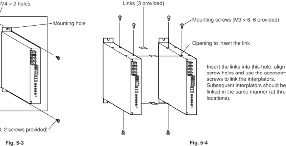
5-9. インターポレータの取付け
インターポレータの取付けは、本体の上下にある取付穴 (U 字溝) を用いて、付属の取付ねじ (M4 × 8) を使って行なっ てください。取付穴の寸法については、図5-3を参照してく ださい。
またインターポレータを2個以上連結して使用する場合に は、必ず付属の連結金具を用いて連結してください。(図5- 4)
図5-3 図5-4
M4タップ穴2個
取付穴
190 mm
取付ねじM4 × 8−2本 (付属品)
連結金具 (付属品) 3枚
取付ねじM3 × 6−6本 (付属品)
連結金具挿入口
この穴に連結金具を挿入してねじ穴 を合わせ、付属のねじで固定します。
連結させるインターポレータにも同 様に取付けて固定します。(3箇所 )
MD20B
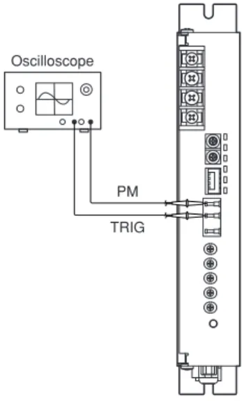
6. 調整
c d
※オシロスコープの設定 水平軸 : 10 µs/div
垂直軸 : 500 mV/div(10:1プローブ使用)
オシロスコープは感度0.1 V以上、
周波数帯域1 MHz以上のもの
図 6-1. スケール信号調整
6-1. スケール信号調整
動作安定化のため、必ずスケール信号調整を行なってくだ さい。
スケール信号調整はスケールを移動しながら以下の手順で 行ないます。スケール信号のリップル率、すなわちエンベ ロープリップルと信号振幅の比が最小になるよう、調整し てください。
組合せスケールによっても異なりますが、リップル率Rの目 安は次のとおりです。
移動速度は0.5〜1 m/minが適当です。
組合せスケール リップル率 R SR721RD 2.5 %以下 SR127 3 %以下 SR128 5 %以下 リップル率 R (%) = ―c × 100
d
ただし、c : エンベロープリップル d : 信号振幅
オシロスコープ
PM TRIG
e GBALボリュームを右廻し (CW) いっぱいに廻し、ス ケールを移動させると図6-2に示すような波形が、観測 されます。
このとき、DC1ボリュームを調整して図6-3に示すよう に、隣り合う山の高さを均一にします。
PM信号の最小振幅が0.5 Vp-p以下になると、アラーム 機能が動作することがあります。
r GBALボリュームを左廻し (CCW) いっぱいに廻し、ス ケールを移動させると、eと同様に図6-2に示すような 波形が観測されます。このとき、DC2ボリュームを調 整して図6-3に示すように、隣り合う山の高さを均一に します。
手順
q オシロスコープを用意し、入力結合切替えをACに水平 掃引軸10 µs/div、垂直軸0.5 V/divに合わせ、ch 1を TRIG端子へ、ch 2をPM端子へ接続させます。このと き、トリガーソースはch 1でとってください。
w ch 2に正弦波が観測されます。スケールの移動に応じ て、この正弦波の位相が動き、エンベロープのリップ ルが観察できます。
GADJボリュームを廻し、あらかじめ正弦波の振幅を約 2 Vp-pに合わせておきます。
10 µs 10 µs
MD20B
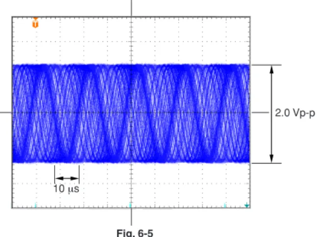
図6-4 図6-5
y 再度GADJボリュームを調整し、図6-5に示すように正弦 波の振幅が1.9 Vp-p〜2.1 Vp-pになるようにします。図6- 5は理想的に調整された状態を示します。
10 µs 10 µs
2.0 Vp-p
erの調整を交互に数回繰り返し、GBALボリュームの 回転によって隣り合う山の高さがずれなくなるまで調 整してください。
t GBALボリュームを中心付近に設定し、スケールを移動 させると図6-4に示すような波形が観測されます。この ときPHASEボリュームを調整し、エンベロープリップ ルが最小になるようにします。また、GBALボリューム も微調整しエンベロープリップルが最小になるように します。
このとき、オシロスコープの感度を上げ (50〜100 mV/
div) 垂直位置調整をして、エンベロープリップルを画面 中央に拡大してからボリューム調整を行なうと容易に 微調整ができます。
6-2. 原点設定
設定方法
本機は、スケール信号と同期した原点を出力させるため に、原点信号とスケール信号の位置関係を設定する必要が あります。スケールおよび原点センサを取付けた後、以下 の設定を必ず行なってください。
1
R.ADJスイッチがOFFになっていることを確認します。2
原点を取り込む方向とは逆方向にスケールを移動さ せ、原点を通過させます。原点通過後、REFランプが消 灯していることを確認してください。原点取り方向とした場合
4 3 R.ADJ DIR
4321
OFFを確認
REF REFランプが消灯
原点取りと逆方向
MD20B
A B C D
4 3 R.ADJ DIR
4321
POSランプが消灯 ONにする
A B C D
3 4
A OFF OFF
B ON OFF
C OFF ON
D ON ON
4 3 R.ADJ DIR
4321
手順5の場合、この設定→
3
R.ADJスイッチをONにします。原点設定モードにな り、POSランプが全て消灯します。4
スケールを移動し、原点を通過させます。5
POSランプが1つ点灯します。6
点灯したPOSランプに対応するMODEスイッチ3、4を 設定します。7
R.ADJスイッチをOFFにします。8
本機の電源を再投入します。注意
※ 原点設定直後は必ず電源の再起動をしてください。原点 設定後、電源を再投入せず、そのまま使用しますと原点 位置がずれることがあります。
※ 原点設定時の送り速度と原点取得時の送り速度はなるべ く同じ速度 (偏差20 %以下) で取得してください。極端に 速度が違う場合は原点ずれを起こす可能性があります。
MD20B
7. 入出力コネクタ仕様
7-1. ヘッドケーブルコネクタ
使用コネクタ: D Sub 15ピン
レセプタクル : DALC-J15SAF (日本航空電子工業 (株) 製) または相当品
注) コネクタの固定ねじはM2.6 (P = 0.45) −2本を使用します。
No. 記号 ケーブル色相
1 H1H 青
2 H1L 黄
3 − −
4 EXT (H) 赤 5 EXT (L) 白 6 DME (H) 茶 7 DME (1) 緑
8 Shield 編組シールド
9 H2H 橙
10 H2L 灰
11 − −
12 − −
13 DME (2) 紫 14 DME (L) 黒
15 Shield 編組シールド
8 7 6 5 4 3 2
15 14 13 12 11 10 9 1
7-3. 出力コネクタ
使用コネクタ:
レセプタクル : MR-20 RMAG プラグ : MR-20LF (付属品) (本田通信工業 (株) 製)
注) No. 1〜6までは電源供給端子です。詳細は 5-7. 電源の供給 方法 を参照してください。
No. 記号 No. 記号
1 注) 0 V 11 PCD
2 注) 0 V 12 ALARM
3 注) 0 V 13 ∗ ALARM
4 注) +5 V 14 PCZ
5 注) +5 V 15 ∗ PCZ
6 注) +5 V 16 PCA
7 0 V 17 ∗ PCA
8 ∗ PCU 18 PCB
9 PCU 19 ∗ PCB
2 1 3 4 5 6 7
13 12 11 10 9 8 14 15 16 17 18 19 20
7-2. 原点コネクタ
使用コネクタ:
レセプタクル : R03-R5F (多治見無線電機 (株) 製)
No. 記号 ケーブル色相
A DME (H) 赤
B DME (1) 白
C DME (L) 黒
D − ∗
E Shield 編組シールド
A B
C D
E
MD20B
出力仕様図 ケーブル断面
編組シールド
外皮
+5 V
0 V
NC MD20B
50 m 以下 (注)
AWG28以上の太さの ツイストペア線 出力:
A / B相、up / down 原点信号 アラーム
受信回路には、DS34C86 (相当品)を使用 してください。
注) 出力ケーブルはノイズ混入防止 のため、短くしてください。
出力コネクタから電源を供給する場合は インターポレータ入力部で+5 V ±5 %を満 足するようにしてください。
8. 外形寸法図
(取付用)
16 2-R2.2
1.8
161
29.2
144
32 (1)
190 200 171
MD20B
Contents
1. NOTES TO USERS ... 1
1-1. General Precautions ... 1
2. INTRODUCTION ... 2 3. FEATURES ... 2 4. SPECIFICATIONS ... 3 5. OPERATION ... 9
5-1. Names of Parts ... 9 5-2. Resolution Setting ... 10 5-3. Output Pulse Width Setting ... 10 5-4. Direction Switching ... 11 5-5. Using the Reference Point ... 11 5-6. The Reference Point when Using a FANUC NC
Machine ... 13 5-7. Power Supply Connections ... 14 5-8. Alarm Signal ... 14 5-9. Interpolator Mounting ... 15
6. ADJUSTMENT ... 16
6-1. Scale Signal Adjustment ... 16 6-2. Reference Point Setting ... 19
7. INPUT/OUTPUT CABLE
CONNECTOR SPECIFICATIONS ... 22
7-1. Head Cable Connector ... 22 7-2. Reference Point Connector ... 23 7-3. Output Connector ... 23
8. OUTSIDE DIMENSIONS ... 25
MD20B
1. NOTES TO USERS
Read all instructions carefully before starting use.
Save this MANUAL for future reference.
1-1. General Precautions
When using Magnescale Co., Ltd. products, observe the following general precautions along with those given specifically in this manual to ensure proper use of the products.
• Before and during operations, be sure to check that our products function properly.
• Provide adequate safety measures to prevent damages in case our products should develop malfunction.
• Use outside indicated specifications or purposes and modification of our products will void any warranty of the functions and performance as specified of our products.
• When using our products in combination with other equipment, the functions and performances as noted in this manual may not be attained, depending upon operating environmental conditions.
Make full study of the compatibility in advance.
• Do not open the cover of this device or put your hand inside.
Otherwise the internal circuit may be broken by static electricity.
• This device is not explosion-proof. Do not use it in the atmosphere of flammable gas.
• This device is not vibration resistant. Do not use it in a place where it is subject to shocks.
MD20B
• Easy-to-extend modular system:
Multiaxis configuration is readily available thanks to the modular design.
• Operates from a single 5 VDC power supply.
• Built-in reference point concurrent with scale signal.
• Alarm function.
• Resolution and output pulse width can be easily set by means of front panel switches.
• Signal outputs include quadrature signal, up/down signal, reference point signal and alarm signal, all of these being output by DS34C87 (or equivalent) differential line drivers.
• Connection to the scale is made using a D-sub connector, enabling high-density packaging.
2. INTRODUCTION 3. FEATURES
The MD20 Series of interpolators was designed to be compact enough to be built into NC equipment.
Connected to a Magnescale® (optional), the MD20B produces A/B quadrature output and up/down output at the same time.
4. SPECIFICATIONS
Resolution 0.1 µm, 0.2 µm, 0.5 µm, 1 µm, 2 µm, 4 µm, 2.5 µm, 5 µm, 10 µm (Note 1)
Output pulse width (Tw) 0.1 µs, 0.2 µs, 0.25 µs, 0.5 µs, 1 µs, 2 µs, 2.5 µs, 5 µs, 10 µs, 20 µs (Note 2) Connecting scale SR721, SR721R, SR721RD, SR721RN, SR801, SR801R, SR127, SR128
Head connecting cable D-sub connector terminated cable Head connecting cable length Max. 50 m/163 feet
Compatible scale Usable cable
SR721, SR801 MK6, MK7
SR127/128 CE11
SR721R, SR801R AK1
SR721RD
SR721RN AK3
Notes:
1. The resolution can be switched by means of the RES switch on the mainframe front panel (refer to Section 5-2).
The resolution set corresponds to the A/B phase difference.
PCA PCB
Resolution
Notes:
2. The output pulse width can be switched by means of the Tw switch on the mainframe front panel (refer to Section 5-3).
The quadrature signal from this interpolator may be output at the set pulse width regardless of the scale movement speed, unlike those of rotary encoders in general.
The receiving circuit is required to receive a pulse of the set width.
MD20B
Output signals Note 1: The displacement is
detected about every 20 µs to generate pulses corresponding to the displacement.
Note 2: Make sure the UP/
DOWN output is received by an up/down counter.
Receiving only one side of the output fails to ensure accurate measuring.
Reference point signal The width of the reference point
signal is approximately 8 mm, and the signal is output for both directions when the scale is moved.
However, always use the leading edge of the same direction as a reference point signal.
A/B quadrature output
Up/Down output (Note 2)
∗ PCAPCA
∗ PCBPCB
∗ PCUPCU
∗ PCDPCD
Tw
Tw Tw/2
Tw : MIN. phase difference
Tw : Min. repeat cycle Tw/2 : Pulse with
8 mm/0.315"
PCZ
∗ PCZ
Output circuit Voltage-differential line drivers (DS34C87) are used to produce outputs. Therefore use voltage-differential line receivers (DS34C86 or equivalent) to receive those outputs.
Maximum response speed The maximum response speed will differ, depending upon the resolution and output pulse width. Refer to Table 3-1.
External reference point circuit PH100-3P (5P, 10P, 15P) or PH100 Magneswitch and PG104 magnet may be used.
Reference point response speed The reference point response speed will differ, depending upon the resolution. Refer to Table 3-2.
Alarm signal If the scale exceeds the maximum response speed or if a head cable connection becomes open, an alarm is triggered. When an alarm is triggered, the ALARM output goes high, and outputs PCA, ∗ PCA, PCB, ∗ PCB, PCU, ∗ PCU, PCD, and ∗ PCD (i.e., all outputs with the exception of the reference point output) go into the high-impedance state.
Alarm clearing To reset the alarm, remove all the causes of the alarm and perform a reset or remove power and apply power once again.
With the alarm triggered, if the external reset is being applied, the alarm signal will not be output and outputs will not go into the high-impedance state. However, the output signals will be stopped.
Reset When the RESET button on the front panel of the mainframe is pressed, the interpolator is reset.
To perform an external reset, short pins 20 and 7 of the output connector.
External reset signal input
Maximum reset time : 10 ms Maximum operation reset time: 10 ms (after the reset is canceled)
PCA, PCB, PCU, PCD, PCZ, ALARM
∗ PCA, ∗ PCB, ∗ PCU, ∗ PCD, ∗ PCZ, ∗ ALARM
+3.3 V External reset signal
input circuit
20: RES
7: 0 V +
MD20B
Power requirements DC +5 V (±5 %) Power consumption MD20B 3 W (max)
Operating temperature range 0 °C to +55 °C/32 °F to 130 °F Storage temperature range –10 °C to +75 °C/14 °F to 167 °F Outside dimensions 171 × 144 × 32 (mm)/
6.7 × 5.7 × 1.3 (inch)
Mass 800 g/1.8 lb
Accessories • Output connector ... 1 set
• Links ... 3
• M3 × 6 screws ... 6
• M4 × 8 mounting screws ... 2
• Label ... 1
• Instruction manual ... 1
Table 3-1 Maximum Response Speed
Resolution (µm) Output pulse width (Tw) (µs)
0.1 0.2 0.25 0.5 1 2 2.5 5 10 20
0.1 42 20 18 9 4.5 2.2 1.8 0.8 — —
0.2 60 42 30 18 9 4.5 3.6 1.8 0.8 —
0.5 60 60 60 45 22 11 9 4.5 2.2 1.1
1 60 60 60 60 45 22 18 9 4.5 2.2
2 60 60 60 60 60 45 36 18 9 4.5
4 60 60 60 60 60 60 60 36 18 9
2.5 60 60 60 60 60 55 45 22 11 5.5
5 60 60 60 60 60 60 60 45 22 11
10 60 60 60 60 60 60 60 60 45 22
(Units: m/min)
MD20B
Table 3-2 Reference Point Response Speed
Resolution Response speed
0.1 µm to 10 µm 5 m/min
Note: The reference point response speed cannot exceed the scale maximum response speed determined by the resolution and pulse width. (For example, the reference point response speed is 2.2 m/min when the pulse width is 10 µs at a resolution of 0.5 µm.)
Although support is provided for reference point location speeds up to 15 m/min in all resolutions, the reference point output position can become unstable due to the effects of speed fluctuations.
If using at 5 m/min or higher, be sure that the feeding speeds when setting the reference point and when locating the reference point are always the same.
The reference point response speed cannot exceed the scale maximum response speed determined by the resolution and pulse width.
5. OPERATION
5-1. Names of Parts
Rear view Side view Front view
Resolution (RES) Terminal block
Output connector
Reference point connector
Head cable connector
POS lamp
Alarm lamp Reference point lamp
Trimmers
Reset button Output Pulse width (Tw)
PM terminal TRIG terminal Reference point (R.ADJ) switch
Direction (DIR) switch MODE switch
MD20B
5-3. Output Pulse Width Setting
The output pulse width of the interpolator can be set using rotary switch Tw on the front panel of the mainframe, as described in the table below.
Pulse width settings
Tw Pulse width (µs)
0 0.25
1 0.5
2 1
3 2
4 2.5
5 5
6 10
7 20
8 0.2
9 0.1
The pulse width is factory-set to 2 (1 µs)
Note: A pulse width of 20 µs and 10 µs cannot be used at a resolution of 0.1 µm.
A pulse width of 20 µs cannot be used at a resolution of 0.2 µm.
5-2. Resolution Setting
The resolution of the interpolator can be set using rotary switch RES on the front panel of the mainframe, as described in the table below.
Resolution Settings
RES Resolution (µm)
0 —
1 10
2 5
3 2.5
4 4
5 2
6 1
7 0.5
8 0.2
9 0.1
The resolution is factory-set to 6 (1 µm)
5-4. Direction Switching
The DIP switch on the front panel of the mainframe can be used to change the way the pulse output is correlated with the scale travel direction.
5-5. Using the Reference Point
When an external reference point or a scale with built-in reference point is used, the interpolator outputs a high precision reference point signal in sync with the scale output signal λ for every 200 µm (refer to Fig. 5-1) at one location within the effective length. When using the reference point signal, use Magnescale Co., Ltd.’s system to maintain the precision.
Also, as shown on the following page, the reference point signal is output for both directions when the scale is moved. However, always use the leading edge of the signal that is output when the scale is moved in the direction selected by the operator beforehand as the reference point signal.
• If power is turned on when the scale is in an area where the REF lamp is on or when reset operation is performed, move the scale out of the area before locating the reference point.
• Do not exceed the maximum response speed when locating the reference point. Refer to the table 3-2 on page 8.
• A scale with built-in reference point can not be used in conjunction with an external reference point.
When above is not observed, reference point error may occur.
MD20B Fig. 5-1 Reference Point Signal Timing
Scale λ signal
REF lamp (reference point gate)
Reference point output (detection direction)
Reference point output (reverse direction)
200 µm
Approx. 8 mm/0.31"
↑ Use this edge as the reference
5-6. The Reference Point when Using a FANUC NC Machine
When using the interpolator in combination with a FANUC system, NC settings for both hardware and software are made on a grid.
• When using a Magnescale, use the grid system in the reference point reset mode. Care is required since the Magnescale reference point position will differ from the machine’s reference point position.
Using the manual continuous feed mode, if the manual feed buttons are used to feed towards the reference point at the rapid traverse rate, when the deceleration limit is reached, deceleration will occur, after which slow-speed feed (FL speed) is used. During this slow- speed feed, if the reference point signal rises, the reference counter will start from that point and a grid of constant spacing will be generated. After this, if a limit switch is tripped, the machine will stop at the first encountered grid point. This stopping point can be shifted arbitrarily using the grid shift setting of the NC system.
In this reference point return operation, it is essential that the reference signal rise after the deceleration dog is turned on in the FL condition. During this operation, the falling edge of the reference signal is completely ignored.
V
Rapid traverse rate Stopping point
FL speed
Deceleration dog
Reference point signal Grid
Set the deceleration dog off point so that it may coincide roughly with the center of a grid interval.
Enabled period for reference point signal rising
The amount of grid shift may be set by means of parameters.
Width determined by the reference counter capacity
MD20B
5-8. Alarm Signal
An alarm signal is output when the scale exceeds maximum response speed or when the head cable becomes disconnected.
When the alarm signal is output, the scale signal output is stopped, causing a high impedance. Operating the machine tool in this condition may cause an accident.
Employ a safety function that, for example, stops the machine tool when an alarm signal is output.
Also, the alarm signal is not sounded for all the failures of the Magnescale system. Therefore, employ adequate safety measures such as overrun prevention, etc.
5-7. Power Supply Connections
Although +5 V is output to the output connector when power is supplied from the terminal block, do not use this power to prevent malfunction.
Power can also be supplied to the interpolator through the output connectors. If a +5 V power source with a capacity of 600 mA or more (per axis) is available on the signal receiver, power can be supplied through the output connectors (pins 4, 5 and 6). In this case, do not supply power from the terminal block.
The interpolator stops signal output for a maximum of one second after power is turned on. In addition, the interpolator may output transient signals when power is turned off. To prevent malfunction within the system, particularly when backing up data, for example, follow the procedure below when turning power on and off.
Turning on power
qTurn on the interpolator’s power.
wTurn on the receiver’s power.
OR
qTurn on the interpolator’s power and the receiver’s power at the same time.
wPerform the initial settings on the receiver.
Turning off power
qTurn off the receiver’s power.
wTurn off the interpolator’s power.
5-9. Interpolator Mounting
Mount the interpolator by using the mounting holes (U grooves) at the top and bottom of the mainframe and the mounting screws (M4
× 8) provided. Refer to Fig. 5-3 for mounting hole dimensions.
Only use the supplied links to join interpolators together (see Fig.
5-4).
Fig. 5-3 Fig. 5-4
M4 × 2 holes
Mounting hole
190 mm/7.48"
Mounting screws (M4 × 8, 2 screws provided)
Links (3 provided)
Mounting screws (M3 × 6, 6 provided)
Opening to insert the link
Insert the links into this hole, align the screw holes and use the accessory screws to link the interplators.
Subsequent interplators should be linked in the same manner (at three locations).
MD20B
6-1. Scale Signal Adjustment
To ensure a stable operation, be sure to adjust the scale signal by following the procedure below while moving the scale. Make sure to perform careful adjustment to minimize the scale signal ripple ratio, i.e., the ratio of the envelope ripple to the signal amplitude.
The ripple ratio R varies depending on the scale connected.
Examples are given below. The scale should be moved at a speed of 0.5 to 1 m/min. (1.64 to 3.28 feet/min.)
Connected scale Ripple ratio R
SR721RD 2.5 % or less
SR127 3 % or less
SR128 5 % or less
R (%) = —c ××××× 100 d
where c = envelope ripple, and d = signal amplitude
6. ADJUSTMENT
Oscilloscope Settings Horizontal axis : 10 µs/div
Vertical axis : 500 mV/div (using 10 : 1 probe)
Oscilloscope sensitivity should be at least 0.1 V and bandwidth should be 1 MHz or greater.
Fig. 6-1 Scale Signal Adjustment
c d
Oscilloscope
PM TRIG
10 µs
Procedure
q Selecting the AC position, set up the oscilloscope for a horizontal sweep of 10 µs/div and vertical-axis sensitivity of 0.5 V/div. Connect CH1 to the TRIG terminal and CH2 to the PM terminal. Set CH1 as the trigger source.
w A sine wave should be observed on CH2.
As the scale moves, the phase of this sine wave moves, and the ripple is observed on the envelope.
Turn the GADJ trimmer to set the amplitude of the sine wave to approx. 2 Vp-p beforehand.
e Turn the GBAL trimmer fully clockwise. Move the scale to observe a waveform as shown in Fig. 6-2.
When doing this, adjust the DC1 trimmer so that adjacent peaks are of uniform height, as shown in Fig. 6-3.
Note alarm may be triggered when the min. PM signal amplitude becomes smaller than 0.5 Vp-p.
r Set the GBAL trimmer to the fully counterclockwise position and move the scale to observe the waveform as shown in Fig.
6-2, as was done in e. When doing this, adjust the DC2 trimmer so that adjacent peaks are of uniform height, as shown in Fig. 6-3.
10 µs
MD20B
Fig. 6-4 Fig. 6-5
Try the adjustments e and r alternately until turning the GBAL trimmer does not cause the adjacent peaks to differ.
t Set the GBAL trimmer to approximately the center position and move the scale to observe the waveform as shown in Fig.
6-4. When doing this, adjust the PHASE trimmer to minimize the ripple on the envelope.
Fine adjust the GBAL trimmer also for minimum ripple.
Fine adjustment may be facilitated by increasing the sensitivity of the oscilloscope (to 50 to 100 m/div) and displaying the ripple, enlarged, in the middle of the frame.
y Readjust the GADJ trimmer so that the sine wave amplitude is 1.9 Vp-p to 2.1 Vp-p, as shown in Fig. 6-5. Fig. 6-5 shows the results of an ideal adjustment.
10 µs 10 µs
2.0 Vp-p
6-2. Reference Point Setting
Setting procedure
In the interpolator, the positional relationship between the reference point signals and scale signals must be set in order to output a reference point in synchronization with the scale signals. After mounting the scale and reference point sensor, be sure to always make the settings below.
1
Check that the R.ADJ switch is set to OFF.2
Move the scale in the opposite direction from where the reference point will be located, and then pass through the reference point. After passing through the reference point, check that the REF lamp is turned off.When setting direction where reference point is located
4 3 R.ADJ DIR
4321
Check that it is OFF
REF REF lamp is off
Opposite direction from reference point location
MD20B
A B C D
4 3 R.ADJ DIR
4321
POS lamp is off Set to ON
A B C D
3 4
A OFF OFF
B ON OFF
C OFF ON
D ON ON
4 3 R.ADJ DIR
4321
In case of step 5, set to this way →
3
Set the R.ADJ switch to ON. This starts the reference point setting mode, and all POS lamps are turned off.4
Move the scale, and pass through the reference point.5
One POS lamp turns on.6
Set MODE switches 3 and 4 corresponding to the POS lamp that turned on.7
Set the R.ADJ switch to OFF.8
Turn the interpolator power off and then on again.∗ Be sure to always turn the power off and then on again after setting the reference point. If you continue to use the interpolator after setting the reference point without turning the power off and then on again, the reference point can be shifted.
∗ Try to make the feeding speeds when setting the reference point and when locating the reference point as close as possible (within 20 %). If the speeds are significantly different, the reference point can be shifted.
MD20B
7. INPUT/OUTPUT CABLE CONNECTOR SPECIFICATIONS
No. Signal Cable color
1 H1H Blue
2 H1L Yellow
3 — —
4 EXT (H) Red
5 EXT (L) White
6 DME (H) Brown
7 DME (1) Green
8 Shield Braided shield
9 H2H Orange
10 H2L Gray
11 — —
12 — —
13 DME (2) Purple
14 DME (L) Black
15 Shield Braided shield
7-1. Head Cable Connector
Connector used: 15-pin D-sub type receptacle
DALC-J15SAF (Japan Aviation Electronics Industry, Ltd.) or equivalent
Note: The connector mounting screws are two M2.6 (P = 0.45 screws)
8 7 6 5 4 3 2
15 14 13 12 11 10 9 1
7-2. Reference Point Connector
Connector used: R03-R5F receptacle (Tajimi Electronics Co., Ltd.) or equivalent.
No. Signal Cable color
A DME (H) Red
B DME (1) White
C DME (L) Black
D — ∗
E Shield Braided shield
7-3. Output Connector
Connector used:
MR-20 RMAG receptacle MR-20LF Plug (Provided) (Honda Tsushin Kogyo Co., Ltd.)
Note: Terminals #1 to #6 are power supply terminals. See “5-7. Power Supply Connections.”
No. Signal No. Signal
1 Note 0 V 11 PCD
2 Note 0 V 12 ALARM
3 Note 0 V 13 ∗ ALARM
4 Note +5 V 14 PCZ
5 Note +5 V 15 ∗ PCZ
6 Note +5 V 16 PCA
7 0 V 17 ∗ PCA
8 ∗ PCU 18 PCB
9 PCU 19 ∗ PCB
A
B C
D E
2 1 3 4 5 6 7
13 12 11 10 9 8 14 15 16 17 18 19 20
MD20B
Output Specifications
Cross section of the cable Shield
Outer coating
+5 V
0 V
NC MD20B
50 m/164' min. (See note below)
Twisted pair (28 AWG or thicker) Outputs:
A/B quadrature, up/down Reference point signal Alarm
Use DS34C86 (or equivalent) as receiving circuit.
Note: Shorten the output cable to improve noise immunity.
When the power is supplied through the output connector, make sure that the voltage at the MD20’s input terminal is +5 V ±5 %.
8. OUTSIDE DIMENSIONS
(For mounting)
16/0.63"
2-R2.2/R0.09"
1.8/0.07"
161/6.34"
29.2/1.15"
144/5.7"
32/1.26"
(1)/(0.04")
190/7.48" 200/7.9" 171/6.73"
MD20B
Inhalt
1. HINWEISE FÜR BENUTZER ... 1
1-1. Allgemeine Vorsichtsmaßnahmen ... 1
2. EINLEITUNG ... 2 3. MERKMALE ... 2 4. TECHNISCHE DATEN ... 3 5. BETRIEB ... 9
5-1. Anordnung und Bezeichnung der Teile ... 9 5-2. Einstellen der Auflösung ... 10 5-3. Einstellen der Ausgangsimpulsbreite ... 10 5-4. Umschalten der Richtung ... 11 5-5. Verwendung des Bezugspunkts ... 11 5-6. Bezugspunkt bei Verwendung einer NC-Ausrüstung von
FANUC ... 13 5-7. Stromversorgungsanschlüsse ... 14 5-8. Alarmsignal ... 14 5-9. Montage des Interpolators ... 15
6. EINSTELLUNG ... 16
6-1. Einstellung des Maßstabsignals ... 16 6-2. Einstellung des Bezugspunkts ... 19
7. KENNDATEN DES E/A-
KABELSTECKVERBINDERS ... 22
7-1. Kopfkabelbuchse ... 22 7-2. Bezugspunktbuchse ... 23 7-3. Ausgangsbuchse ... 23
8. AUSSENABMESSUNGEN ... 25
MD20B
1. HINWEISE FÜR BENUTZER
1-1. Allgemeine Vorsichtsmaßnahmen
Beachten Sie bei der Verwendung von Magnescale Co., Ltd.
Produkten die folgenden allgemeinen sowie die in dieser Bedienungsanleitung besonders hervorgehobenen Vorsichtsmaßnahmen, um eine sachgerechte Behandlung der Produkte zu gewährleisten.
• Vergewissern Sie sich vor und während des Betriebs, dass unsere Produkte einwandfrei funktionieren.
• Sorgen Sie für geeignete Sicherheitsmaßnahmen, um im Falle von Gerätestörungen Schäden auszuschließen.
• Wenn das Profukt modifiziert oder nicht seinem Zweck entsprechend verwendet wird, erlischt die Garantie für die angegebenen Funktionen und Leistungsmerkmale.
• Bei Verwendung unserer Produkte zusammen mit Geräten anderer Hersteller werden je nach den Umgebungsbedingungen die in der Bedienungsanleitung beschriebenen Funktionen und Leistungsmerkmale möglicherweise nicht erreicht. Bitte überprüfen Sie die Kompatibilität zwischen den verschiedenen Geräten sorgfältig im Voraus.
• Öffnen Sie auf keinen Fall die Abdeckung dieses Gerätes, und stecken Sie Ihre Hand nicht das Geräteinnere. Anderenfalls kann die eingebaute Schaltung durch eine Einwirkung von statischer Elektrizität beschädigt werden.
• Dieses Gerät ist nicht explosionsgeschützt. Es darf daher nicht in einer Atmosphäre verwendet werden, die entzündliches Gas enthält.
• Dieses Gerät ist nicht schwingungsfest. Es darf daher nicht an einem Ort verwendet werden, an dem es Erschütterungen ausgesetzt ist.
Bitte lesen Sie vor der Inbetriebnahme dieses Gerätes alle Anweisungen aufmerksam und vollständig durch, und heben Sie diese Anleitung anschließend für sofortige Bezugnahme griffbereit auf.
MD20B
• Leicht ausbaufähiges Modulsystem:
Einfach herzustellende Mehrachsen-Konfiguration dank modularer Konstruktion
• Betrieb über eine einzige 5-V-Gleichspannungsquelle
• Integrierter Impulsbezugspunkt parallel zum Maßstabsignal
• Alarmfunktion
• Bequeme Einstellung von Auflösung und Ausgangsimpulsbreite über Schalter an der Frontplatte
• Die Ausgangssignale umfassen Quadratursignal, Aufwärts/
Abwärts-Signal, Bezugspunktsignal und Alarmsignal, die alle über Differentialleitungstreiber DS34C87 (oder gleichwertige) ausgegeben werden.
• Der Anschluss an den Maßstab erfolgt über einen D-sub- Steckverbinder, wodurch eine hohe Integrationsdichte erzielt wird.
2. EINLEITUNG 3. MERKMALE
Die Interpolatoren der Baureihe MD20 weisen eine kompakte Konstruktion auf, die ihren Einbau in NC-Ausrüstungen gestattet.
Nach Anschluss an ein Magnescale® (Option) erzeugt die Baureihe MD20B gleichzeitig ein A/B-Quadratur- und ein Aufwärts/Abwärts- Ausgangssignal.
4. TECHNISCHE DATEN
Auflösung 0,1 µm, 0,2 µm, 0,5 µm, 1 µm, 2 µm, 4 µm, 2,5 µm, 5 µm, 10 µm (Anmerkung 1) Ausgangsimpulsbreite (Tw) 0,1 µs, 0,2 µs, 0,25 µs, 0,5 µs, 1 µs, 2 µs, 2,5 µs, 5 µs, 10 µs, 20 µs (Anmerkung 2) Anschließbare Maßstäbe SR721, SR721R, SR721RD, SR721RN, SR801, SR801R, SR127, SR128
Kopfkabel Kabel mit D-sub-Steckverbinder
Kopfkabellänge 50 m max.
Kompatible Maßstäbe Geeignetes Kabel
SR721, SR801 MK6, MK7
SR127/128 CE11
SR721R, SR801R AK1
SR721RD
SR721RN AK3
Anmerkung:
1. Die Auflösung kann über den RES-Schalter an der Frontplatte umgeschaltet werden (siehe Abschnitt 5-2). Die eingestellte Auflösung entspricht jeweils der A/B-Quadraturdifferenz.
PCA PCB
Auflösung
Anmerkung:
2. Die Ausgangsimpulsbreite kann über den Tw-Schalter an der Frontplatte umgeschaltet werden (siehe Abschnitt 5-3).
Im Gegensatz zu Drehgebern allgemein kann das Quadratursignal dieses Inter polators ungeachtet der Verfahrgeschwindigkeit des Maßstabs mit der eingestellten Impulsbreite ausgegeben werden. Die Empfangsschaltung muss zum Empfang eines Impulses der eingestellten Breite in der Lage sein.
MD20B
Ausgangssignale Anmerkung 1: Die Verschiebung wird
alle 20 µs erfasst, um Impulse erzeugen zu können, die dem Ausmaß der Verschiebung entsprechen.
Anmerkung 2: Sorgen Sie unbedingt dafür, dass das Aufwärts/Abwärts- Ausgangssignal von einem Aufwärts/
Abwärts-Zähler empfangen wird. Eine korrekte Messung ist nicht gewährleistet, wenn nur eine einzige Seite des
Ausgangssignals empfangen wird.
Bezugspunktsignal Die Breite des Bezugspunktsignals
beträgt ca. 8 mm, und das Signal wird für beide Richtungen ausgegeben, wenn der Maßstab verfahren wird.
Achten Sie jedoch darauf, stets die positive Flanke der gleichen Richtung als Bezugspunktsignal zu verwenden.
A/B-Quadratur-Ausgangssignal
Aufwärts/Abwärts-Ausgangssignal (Anm. 2)
∗ PCAPCA
∗ PCBPCB
∗ PCUPCU
∗ PCDPCD
Tw
Tw Tw/2
Tw: min. Phasenabstand
Tw : min. Wiederholzyklus Tw/2 : Impulsbreite
8 mm PCZ
∗ PCZ