PAPER
Special Section on VLSI Design and CAD AlgorithmsHigh Level Congestion Detection from C / C ++ Source Code for High Level Synthesis
Masato TATSUOKA†a),Member andMineo KANEKO†b),Fellow
SUMMARY High level synthesis (HLS) is a source-code-driven Reg- ister Transfer Level (RTL) design tool, and the performance, the power consumption, and the area of a generated RTL are limited partly by the de- scription of a HLS input source code. In order to break through such kind of limitation and to get a further optimized RTL, the optimization of the input source code is indispensable. Routing congestion is one of such problems we need to consider the refinement of a HLS input source code. In this pa- per, we propose a novel HLS flow that performs code improvements by de- tecting congested parts directly from HLS input source code without using physical logic synthesis, and regenerating the input source code for HLS.
In our approach, the origin of the wire congestion is detected from the HLS input source code by applying pattern matching on Program-Dependence Graph (PDG) constructed from the HLS input source code, the possibility of wire congestion is reported.
key words: wire congestion, high level synthesis, source code compiler, LLVM
1. Introduction
From the request of short Time-to-Market, the high level synthesis (HLS) technology is indispensable for dealing with the increase of design complexity and the advance of deep-submicron technology. The advantages of utilizing HLS technology include saving RTL design time, easiness of mapping the process technology to RTL, etc. The pro- ductivity of the design with using HLS improves consider- ably over the RTL hand-coding. However, in many cases, the output RTL design generated by HLS technology may have a higher wire congestion which may lead to timing failure, extra power consumption, and extra area overhead in the layout design phase. In worst case, it results in de- sign failure due to a lack of routability of wires in congested layout areas.
In many conventional design flows, routing conges- tion problems cannot be recognized before applying phys- ical logic synthesis which is a simplified layout phase prior to detailed Place and Route (P&R). When the wire conges- tion is found, we need to identify the root cause of it and, if necessary, modify the HLS input source code described in SystemC or C/C++in order to improve the RTL design generated by the HLS. In general, the improvement and the correction of the HLS input source code are repeated, which degrades design productivity. The abstraction level of
Manuscript received March 16, 2020.
Manuscript revised July 7, 2020.
†The authors are with Japan Advanced Institute of Science and Technology, Nomi-shi, 923-1292 Japan.
a) E-mail: [email protected] b) E-mail: [email protected]
DOI: 10.1587/transfun.2020VLP0012
HLS input source code is higher than the conventional Ver- ilog/VHDL hardware description model. This abstraction leads to the difficulty of grasping intuitively the hardware implementation from the HLS input source code. Moreover, it is still more difficult to resolve congestion problems due to the lack of physical information in HLS. It further aggra- vates productivity. Introduction of a new congestion aware HLS design flow is imperative in order to mitigate the prob- lem.
The wire congestion has long been a well-known prob- lem in logic synthesis. The methods for congestion mapping and congestion minimization during logic synthesis have been proposed in[5],[6]. These methods explore the trade- offs between area minimization and congestion minimiza- tion by logic synthesis. The commercial logical synthesis tools can improve congestion and timing based on the phys- ical information obtained from layout tools[7]. However, this approach uses logic synthesis and cannot be applied to HLS input source code.
As for congestion aware HLS, layout-friendly HLS ap- proach[4]has been proposed to improve the congestion by changing the register/resource allocation of RTL architec- ture generated from HLS and by placement within slack time of interconnect delay and logic delay. The approach in[1]is based on Simulated Annealing with the cost func- tion value which is obtained from a previous placement. J.
Cong and et al.[3]proposed a method of structural metrics called spreading score to handle the congestion problem at the HLS phase. The approach proposed in [8]is a design flow that links congestion data obtained from physical logic synthesis and the synthesis data obtained from HLS with focusing on RTL instances (MUXes and DEMUXes). The HLS input source code will then be rewritten so as to elimi- nate congestion, which causes the iteration of detection and improvement of wire congestion because the link between the wire congestion and the HLS input source code is still unclear.
Part of wire congestion issues in the high level synthe- sis originates in a HLS input source code and a RTL design generated with specified synthesis constraints and HLS di- rectives. As for the latter, the wire congestion can be mit- igated by changing synthesis constraints and/or HLS direc- tives, and previous approaches mentioned above are in this category. On the other hand, as for the former, the HLS input source code must be modified for avoiding wire con- gestions, and none of the above mentioned approaches tried to detect wire congestion directly from HLS input source Copyright c2020 The Institute of Electronics, Information and Communication Engineers
1438
IEICE TRANS. FUNDAMENTALS, VOL.E103–A, NO.12 DECEMBER 2020
code.
In this paper, we propose an approach to detect wire congestion directly from HLS input source code without re- lying on physical logic synthesis. Our approach is based on the detection of the generation of MUXes and DEMUXes from HLS input source code, and our method is imple- mented as a part of the source code complier phase which is placed before the HLS phase in the HLS design flow. As a concreate realization of our approach, we have focused on two major types of code patterns for detecting wire conges- tion in this paper. While these two types of pattern may not cover all potential codes to yield wire congestion, our pro- posal would provide an important framework which can be extended by involving detection routines for different types of potential code to yield wire congestion.
The rest of this paper is organized as follows. In Sect. 2, the problems of the conventional congestion aware high level synthesis flow are discussed. Section 3 introduces the proposed congestion aware high level synthesis flow, and explains our approach for detecting wire congestion from HLS input source code in detail. The implementation and experimental results are presented in Sect. 4. Finally, we conclude this paper and discuss future works in Sect. 5.
2. Conventional Flow and Problems
2.1 Conventional Congestion Aware High Level Synthesis The design size capable with using HLS is much higher than that of RTL. Although the productivity improves, the design of high abstraction level leads to the loss of hardware (HW) description and makes it difficult to consider physical de- sign. When a RTL design generated by HLS is placed and routed, wire congestion may occur, which results in timing failure, detours of wires, insertion of extra drivers, a large chip area, etc.
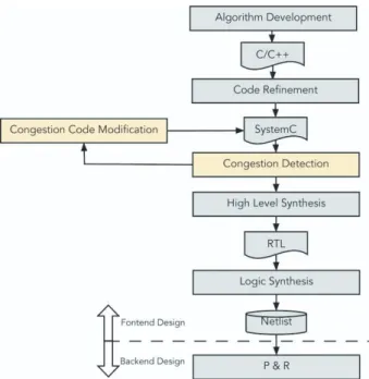
A design flow to improve the congestion by back an- notating to HLS input source code from RTL design gen- erated by HLS has been proposed in[8], which is shown in Fig. 1. The design flow has two additional steps; Con- gestion Detection and Congestion Improvement. In Con- gestion Detection step, a physical logic synthesis tool is used for detecting the congestion. From the analysis of past layout results, they found that almost all congestions come from large multiplexers (MUXes) and de-multiplexers (DEMUXes). After running the physical logic synthesis, the congestion aware HLS design flow in Fig. 1 reports the MUXes and DEMUXes located in the congested area.
In Congestion Improvement step, designers analyze the congestion information, HLS input source code and HLS di- rectives to find the root causes of the congestion. According to the identified root causes, designers will improve conges- tion either by changing the HLS input source code or by changing HLS directives to generate different RTL designs.
Before the netlist is sent to a layout design team, the con- gestion can be fixed earlier by these two steps.
Fig. 1 Congestion aware HLS design flow[8].
2.2 Problem of Conventional Congestion Aware HLS Flow
The conventional design flow has two major problems in connection with wire congestion as follows.
The mixed causes of the congestion:
In the conventional design flow, the congestion report is obtained only after physical logic synthesis applied to a RTL design generated by HLS. The congestions indi- cated in the report include not only logic-induced conges- tions but also layout-induced congestions. Logic-induced congestion can be further divided into several categories depending on its root cause, such as HLS-input-source- code-induced congestion, resource-sharing-in-HLS-induced congestion [4], logic-synthesis-induced congestion. HLS- input-source-code-induced congestion (HLS-input-induced congestion, in short) is a wire congestion which originates in a HLS input source code. An example of HLS-input- induced congestion can be seen in the pair of HLS input source code given in Fig. 2 and a datapath circuit shown in Fig. 3, which is obtained from the code by HLS, where DE- MUXes are generated as a result of HLS input source code description, and they may cause wire congestion depending on the numbers and the sizes of these DEMUXes. Addi- tional wire congestions may also occur as a side effect of other logic-induced congestion around MUXes/DEMUXes.
A number of congestions may be yielded by the mixture of several different causes as well. In order to cancel or mitigate the congestions, individual causes of each conges- tion must be identified so that HLS-input-induced conges- tion is resolved at the HLS input source code level, resource- sharing-in-HLS-induced congestion is resolved in HLS with changing HLS constraints and/or directives, logic-synthesis-
Fig. 2 Sample source code in[8].
induced congestion is resolved at the logic synthesis level, and layout-induced congestion is resolved at the layout level. However the identification of individual causes of each congestion from the report obtained only after phys- ical logic synthesis is difficult.
Congestions caused by unspecified multiplexors:
From the analysis of past layout results, it was found that almost all congestions come from large MUXes and DEMUXes. However, as far as the authors know, there was no enough discussion on the relation between the size of MUXes/DEMUXes and the degree of congestion. In ad- dition, considering the detection and the reduction of the wire congestion due to large MUXes/DEMUXes, we need to identify the instruction lines in HLS input source code, which will generate MUXes/DEMUXes, and also we need to evaluate the size of each MUX/DEMUX from the instruc- tion lines. The conventional design flow does not handle these issues.
In this paper, we focus on wire congestion induced by HLS input source code, and present a method to detect it.
Fig. 3 HLS output RTL in[8].
3. Detection of (DE)MUX-Originated Wire Conges- tions
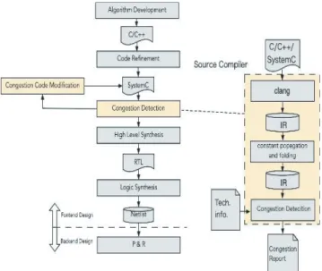
3.1 Congestion Aware High Level Synthesis Flow The congestion aware high level synthesis flow proposed in this paper is illustrated in Fig. 4[12], in which our proposed congestion detection phase is incorporated. In this conges- tion detection phase, we will detect code lines in the HLS input source code which yield MUXes and DEMUXes, and estimate how heavy wire congestion is to occur by these de- tected MUXes and DEMUXes.
As for HLS-input-induced wire congestion, we fo- cus on wire congestion induced by MUXes/DEMUXes. A MUX will be introduced into RTL model when (Fact 1);
with respect to a single variable, there exist multiple ways to compute its value, and one of them is chosen in run-time by SWITCH statement, IF statement, etc., or (Fact 2); with respect to a single computation result, there exist multiple candidate variables to which the result is substituted, and one of them is chosen in run-time. Normally, an ARRAY whose index is determined in run-time is the object for this Fact 2. Our detection of (DE)MUX relies on the above two cases. We introduce pattern matching on Program Depen- dence Graph (PDG) [11]and extended PDG (ePDG). The final decision of wire congestion (or not) will be made by comparing the estimated number of wires running around MUX/DEMUX with an available number of wires running on a unit area in the physical design.
3.2 Program Dependence Graph LetGp =
Np,Ep,entry
be a (statement-level) PDG, where Np is the set of statements in a source code p, Ep ⊆ Np ×Np × {DD,CD,true,f alse} is the set of edges, and entry ∈ Np represents a unique starting statement. For each edge (s,t,type),sandtare source node and destination
1440
IEICE TRANS. FUNDAMENTALS, VOL.E103–A, NO.12 DECEMBER 2020
Fig. 4 Proposed congestion aware HLS flow.
node, respectively, andtype∈ {DD,CD,true,f alse}repre- sents edge type, whereDDrepresents data dependence,CD represents control dependence (true/false of the condition is not concerned),truerepresents control dependence valid for the case that the condition is fulfilled, and f alserepresents control dependence valid for the case that the condition is not fulfilled.
LetREF(n) be the set of variables referred from a state- mentn∈NP, and letDEF(n) be the set of variables whose values are determined in the statementn ∈ NP. It is clear that (s,t,DD)∈Epmeans that there exist a variablewsuch thatw∈DEF(s) andw∈REF(t).
3.3 Extended Program Dependence Graph
We will extend the definition of PDG so as to treat depen- dence relation between variables (and constant data) and instructions within a statement as well. We will treat in- structions and variables/constant which appear in a single program statement as nodes of extended PDG (ePDG) and consider edges connecting them.
For example, the statement-level PDG for a source code shown in Fig. 5 is illustrated in the left side of Fig. 6, where node 4 and node 6 correspond to the statements in the 4th line and 6th line, respectively. On the other hand, the right hand side of Fig. 6 is an ePDG for the same source code, in which variable/instruction-level dependence is rep- resented in addition to the statement-level dependence by in- troducing nodes “num” and “ret” and an edge between them instead of the statement node “4”, and by introducing nodes
“num”, “−1”, “*” and “ret” and edges between them instead of the statement node “6”. A node of the original statement- level PDG, which corresponds to one statement, will be con- sidered as a super node (an oval drawn with dashed line in
Fig. 5 A sample program code.
Fig. 6 Statement-level PDG (left hand side) and extended PDG (right hand side) for the sample code shown in Fig. 5.
Fig. 7 ePDG pattern of Pattern 1.
the right of) in the ePDG.
3.4 Pattern Matching on Dependence Graph
In order to extract MUXs/DEMUXs from a PDG/ePDG, the following patterns are considered.
Pattern 1: Corresponding to Fact 1, Pattern 1 is used for finding a variable which is to be computed in multiple ways and is determined in run-time.
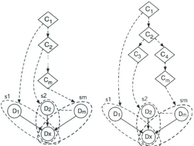
Pattern 1 is a structural pattern on PDG/ePDG, which consists of a control node C and statement nodes as the des- tinations of the control dependence relations from C, which contain a common data node D to be determined in the statement. Such a data node D will be hereinafter called a “VART”; a Variable selected At Run Time. Figure 7 illus- trates the structure of Pattern 1, in which C1 is a common control node of multiple destinations (the set of super nodes {s1, s2, . . . , sm}), and Dx is a common data node in all s1, s2, . . . , sm, whose value is to be computed in one of the statements (that is, a VART).
Pattern 2: Corresponding to Fact 2, Pattern 2 is used for finding an ARRAY whose index is determined only run time.
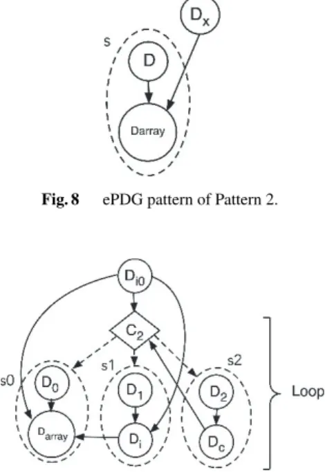
Fig. 8 ePDG pattern of Pattern 2.
Fig. 9 ePDG pattern of Pattern 2 with loop.
On the ePDG, Pattern 2 consists of an ARRAY node Darray, a VART node Dx and a data dependence (Dx, Dar- ray, DD), where Dx is used as the index for Darray. Figure 8 illustrates Pattern2.
Pattern 2 in a loop: ARRY type variable is frequently used together with for/while/do-while statement, and the size of (DE)MUX which affects wire congestion is tend to be larger in particular when for/while/do-while statement cannot be unrolled and the array index cannot be determined during the high level synthesis.
Figure 9 shows an example of PDG/ePDG which in- cludes ARRAY computation in a loop. At first, by detecting a cycle (C2 → D2 → Dc → C2) which includes a con- trol node C2, we recognize that the control nodeC2 con- trols a loop. Further, by checking statement-level nodes s0, s1, and s2 which are destinations oftrue-type Control De- pendency fromC2, we recognize that an ARRAY type vari- ableDarray[i] is included in the loop as the destination of data dependency (D0,Darray[i],DD). Next, we will check whether the detected loop can be unrolled or not. To do so, we find that the indexiof Darray[i] is determined ei- ther by the data dependency (Di0,Darray[i],DD) or by the data dependency (Di,Darray[i],DD), where for the latter we can further trace back toDi0by another data dependency (Di0,Di,DD). As a result, we can recognize that the indexi ofDarray[i] is determined fromDi0which is outside of the loop controlled byC2, and if thisDi0 is a VART which is detected by Pattern 1, the loop controlled byC2 cannot be unrolled by a HLS tool.
As the result of the pattern matching, we will collect the information listed below.
Darrayp: the name of array data whose index is VART Widthp: Bit width ofDarrayp
Rangep: Index range ofDarraypwhere
Rangep=“maximum index forDarrayp”
−“minimum index forDarrayp”+1 Note that the information about the maximum (mini- mum) index for Darrayp is obtained statically or dynami- cally. It is possible to determine the range of the index stat- ically if the first index and the final index of the array are given with constants (in some cases after applying constant folding and constant propagation as preprocessing). On the other hand, when the index is determined as the result of computations and the range of the possible value for the in- dex cannot be determined statically, the program will be ex- ecuted to monitor the possible values of the index, and the range of the index is then determined.
3.5 Congestion Judgement
Wire congestion will be graded in general with the ratio be- tween the factual number of wires passing through a bound- ary separating two regions and the maximum available num- ber of wires passing through the same boundary. Here we consider the region for the layout of MUXes/DEMUXes.
Since we are at the stage of HLS input source code and it is hard to estimate physical level layout exactly, it is as- sumed that MUXes/DEMUXes are placed nearby to form a MUXes/DEMUXes layout region.
The area (nominal area) of the MUXes/DEMUXes lay- out region, Anominal, will be estimated by the area of two- input MUX (two-output DEMUX),AMU X, multiplied by the number of two-input MUXes (two-output DEMUXes).
Anominal=AMU X×
P−1
X
p=0
Rangep−1
×Widthp
The “space utilization” factor u is also considered, which is the ratio of the nominal area over the actual area of MUXes/DEMUXes layout region, and the area of MUXes/DEMUXes layout region,Aregion, is estimated as its nominal area divided by the space utilization u. Note that the space utilizationumay take a positive value equal to or smaller than 1.
Aregion= Anominal
u
Finally, we will estimate the maximum available number Xof wires passing through the boundary of the MUXes/DEMUXes layout region as follows.
X=
Mmax
X
L=Mmin
`
PL ×rL (1)
where each symbol represents a parameter as follows.
• ` = p
Aregion: the square root of the area of MUXes/ DEMUXes layout region
• L: index number of each available layer
1442
IEICE TRANS. FUNDAMENTALS, VOL.E103–A, NO.12 DECEMBER 2020
Mmin≤L≤Mmax
• PL: wire pitch in a layerLof a target technology
• rL: wire availability ratio for a layerL
Note that`/PLis an estimate of the maximum number of wires passing through one edge of a square region hav- ing its areaAregion, and it is used as a bare estimate (before multiplyingrL) of the available number of wires. Note also that the wire availability ratiorLis a parameter which repre- sents the allowable maximum number of wires to be placed in a layer over a multiplexor cell divided by the maximum number of wires computed from a given wire pitch, and it is a real number no larger than 1. The values of parametersPL andrLare obtained from the physical logic library and the design specification.
On the other hand, the factual numberZ of wires re- quired around the MUXes/DEMUXes of all arrays{Darray0, Darray1,· · ·, DarrayP−1}detected by the pattern matchings is computed as follows.
Z=
P−1
X
p=0
nWidthp×
Rangep+1 +l
log2(Rangep)mo
whereWidthp×
Rangep+1
for inputs to be selected and an output as the result of MUX (or an input to DEMUX and possible outputs) and l
log2(Rangep)m
is for control signal for selecting one fromRangepalternatives.
Using the factual number of required wires Z and the estimated number of available wires X, the congestion judgement is done as follows.
if(Z>X){
There is a possibility of congestion.
}
If the inequality in the if-statement is true, it is judged that the wiring is “congested (C)”, and if it is false, it is judged that it is “not congested (NC)”.
As it is explained in this section, our challenge is to de- termine the wire congestion from C/C++source code which will be an input to the high level synthesis. Our decision does not rely on the detailed logic synthesis nor physical de- sign, but relies on the numbers of required wires and avail- able wires which are estimated under a quite simple layout model. One way to bridge the gap between an actual design and an estimation would be to incorporate more sophisti- cated layout model, and another way would be to incorpo- rate a compensation factor which is supported by the statis- tics of the gap in actual design experiences. These directions to improve our approach are beyond the scope of this paper, and remain as future works.
4. Experiments
4.1 Implementation
Our proposed congestion detection has been implemented as a part of LLVM-based Source Code Compiler. As it is shown in Figure 10, the PASS flow consists of three proce- dures, i.e., clang, constant propagation and folding, and our congestion detection.
The Frontend in this flow is clang for parsing, validat- ing and diagnosing errors in the input source code, then the translation of the code into LLVM IR. The IR is fed through several analysis and optimization PASSes to improve the code. The HLS input source code has parameters that can be replaced with constants and others that can’t be replaced.
Before entering to the PASS to analyze a ePDG for con- gestion detection, the IR is fed into “constant propagation and constant folding” phase (PASSes : “–constprop” and “–
constmerge” provide by LLVM) to replace a parameter in- volving only constant operands with a constant value. After those pre-processing, the wire congestion detection PASS executes the pattern matching, congestion estimation, con- gestion judgement as mentioned in the previous section and reports the result of congestion judgement.
4.2 Congestion Detection
An input source code shown in Fig. 2 is used in the exper- iment. This code is the same with one example tested in [8]. A RTL design as an output of HLS is synthesized by C-to-Silicon compiler (CtoS). The operations applied to the 6 different arrays from A[] to F[] on lines 35 to 40 in the sample code are implemented using DEMUXes as shown in Fig. 3, which was reported in[8]. Especially when directive is “loop unroll”, a terrible wire congestion occurs. In the ex- periment, the variants of the input source code are prepared,
Fig. 10 The PASS flow chart in the source code compiler.
where each variant contains the different number of arrays, i.e., the array A[] alone up to all of six arrays from A[] to F[].
In our experiment, as for the physical information, we assume that the cell utilization is 50% (or 70%), multiplexor cell area is 0.7µm2, and the wire availability ratio r1 of Metal 1st layer (M1) is 0% because many wires are used for intra-cell connections. The layers other than M1 can be used for wiring between RTL components and wires of power supply in chip. We have tested two cases about avail- able layers for multiplexors. In Case 1, four layers from M1 to M4 are available, while in Case 2, three layers from M1 to M3 are available. The physical information described in the Tech.info. file is shown in Fig. 11.
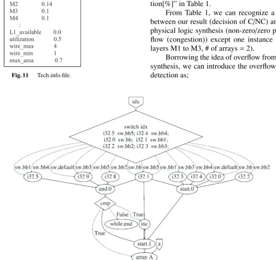
The congestion detection PASS analyzes ePDG and executes pattern matching to detect wire congestion. The ePDG of the test code with one array A[] is shown in Fig. 12.
Considering ePDG of the test source code,Di0of pattern 1 is “start.0” and “end.0”. where the numerical extension “.0”
is to avoid the overlap of the names of nodes when there are multiple variables having the same name. Dx of pattern 2 is “start.0”. The loop part is (“start.1”→“cmp”→ “inc”
→“start.1”). The array node is “array A”. The parameter
Fig. 11 Tech.info.file.
Fig. 12 ePDG of the test code with one array.
“start.1” that is used in the while statement can take a value from 0 to 9, so the parameter “start.1” can be implemented as a 4-bit variable. For example, regarding array A[], the number Z of signal wires which are selected via MUX can be calculated from the ranges of “start” and “end” for the array node, maximum index=9, minimum index=0, and the bit width of the array (we assume it to be 32 bits).
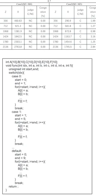
Table 1 shows experimental results for two different cases of available layers, for two different cases of utiliza- tion parameter 0.5 or 0.7, and for each of 6 variants of input source codes, each of which has different number of arrays.
The columns “Z”, “X” and “judge C/NC” show our results of the number of required wires, the number of available wires and the decision of congested (C) or not congested (NC), while the column “Congestion[%]” shows the result of the wire congestion obtained from the physical logic syn- thesis[7].
Physical logic synthesis[7] is a simplified layout de- sign phase after the high level synthesis and prior to detailed Place and Route. It lays out macros, ports, standard cells, blocks, etc. in consideration of the timing of logic synthe- sis, and acquires the information of connection wires. From this information, it computes the overflow percentage of the number of wires required in a predetermined unit area over the number of available wires, and reports the result to a designer, which is the value shown in the column “Conges- tion[%]” in Table 1.
From Table 1, we can recognize a proper agreement between our result (decision of C/NC) and the result of the physical logic synthesis (non-zero/zero percentage of over- flow (congestion)) except one instance (utilization = 0.5, layers M1 to M3, # of arrays=2).
Borrowing the idea of overflow from the physical logic synthesis, we can introduce the overflow in our congestion detection as;
1444
IEICE TRANS. FUNDAMENTALS, VOL.E103–A, NO.12 DECEMBER 2020
Table 1 Experimental results.
Overflow=
0 i f Z≤X Z−X
X i f Z>X
where Z is the number of required wires and X is a esti- mated number of available wires as it is explained before. If we apply this overflow to our experimental result, we have 0% for utilization 0.5 and layers M1 to M4, 3.42% for uti- lization 0.5 and layers M1 to M3, 0% for utilization 0.7 and layers M1 to M4, and 22.4% for utilization 0.7 and layers M1 to M3. If we compare these values with the congestion reported by the physical logic synthesis for the congested cases, there is un-negligible gap for their absolute values, but we can see a similar tendency, i.e., the congestion for utilization 0.7 and layers M1 to M3 reported from the physi- cal logic synthesis is about 5.2 times larger (in average) than that for utilization 0.5 and layers M1 to M3, while it is about 6.5 times larger in our overflow estimation from C/C++
source code. Our overflow estimation relies on the numbers of required wires and available wires which are estimated under a quite simple layout model. In order to bridge the gap between an actual design and an estimation would be to incorporate more sophisticated layout model, and/or to in- corporate a compensation factor which is supported by the statistics of the gap in actual design experiences.
4.3 Examples of Code Rewriting for Mitigating Wire Con- gestion
The formal discussion on how HLS input source code can be rewritten in order to mitigate HLS input source code- induced wire congestion is beyond the scope of this paper.
In this subsection, using the same test source code (Fig. 2) with the previous experiment, two examples of rewriting of the source code are presented, by which HLS-input-induced wire congestion is mitigated. The basic idea of rewriting is the avoidance of ARRAY computation in a loop, which is indexed by a VART.
Figure 13 shows the first example of rewriting of Fig. 2.
In this rewriting, ARRAY computations are moved into in- dividual “case” blocks, and “UNROLL” option is given to the loop. Within each case block, the start index and the last index are no longer VARTs. Figure 14 shows the second example of rewriting. In this rewriting, the loop computa- tion is eliminated by replacing it with conditional branches.
Fig. 13 First example of rewriting HLS input source code.
The actual transformation from Fig. 2 to Fig. 14 is briefly demonstrated in Appendix A.
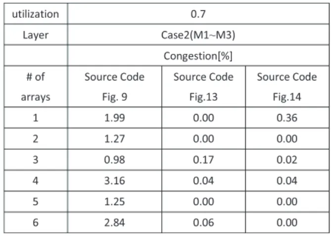
Table 2 shows the result of Physical logic synthesis for Case2 (using layers M1 through M3) with utilization 0.7, from which we can find that the wire congestion is properly mitigated by using rewritten HLS input source codes.
4.4 Comment on Applicability
While the test sample source code used in the experiment (Fig. 2) is composed with “switch-case” statement for con- ditional branching and “while” statement for looping, our detection from C/C++ source code relies on the pattern matching on ePDG, and it does not strongly rely on spe- cific instructions. Conditional branching by “if-else” state-
Fig. 14 Secondt example of rewriting HLS input source code.
Table 2 Comparison of wire congestions reported by Physical logic syn- thesis.
ment, nested-“if” statement, looping with “do-while” state- ment and “for” statement can be analyzed similarly (see Appendix-B). Current version of our software implemen- tation of wire congestion detection is a test version with a limited ability of pattern matching on ePDG, but the appli- cability to a larger and complicated HLS input source code would be improved by enhancing the pattern matching abil- ity without changing the theoretical bases proposed in this paper.
5. Conclusion and Future Work
This paper proposes a wire congestion detection from
C/C++ source code in a high level synthesis flow. Our approach is based on the detection of the generation of- MUXes and DEMUXes, and the comparison between the number of required wires and the estimated number of avail- able wires. The detection algorithm is implemented as a part of the source code complier phase which is placed be- fore the HLS phase in the HLS design flow. Our proposed flow can improve two problems in the conventional conges- tion aware HLS flow, i.e., the identification of logic-induced cause of congestion and the relation between the number of MUXes/DEMUXes and the occurrence of wire congestion.
Our congestion decision relies on the numbers of re- quired wires and available wires which are estimated un- der a quite simple layout model. One way to bridge the gap between an actual design and an estimation would be to incorporate more sophisticated layout model, and another way would be to incorporate a compensation factor which is supported by the statistics of the gap in actual design experi- ences. These directions to improve our approach remain as future work.
References
[1] J. Wu, C. Ma, and B. Huang, “Congestion aware high level synthesis combined with floorplanning,” PACIIA’08, pp.935–938, 2008.
[2] J. Cong, B. Liu, G. Luo, and R. Prabhakar, “Towards layout-friendly high level synthesis,” ISPD’12, pp.165–172, 2012.
[3] J. Cong and B. LiuA. “Metric for layout-friendly microarchitecture optimization in high level synthesis,” DAC’12, pp.1239–1244, 2012.
[4] J. Um, J. Kim, and T. Kim, “Layout-driven resource sharing in high- level synthesis,” ICCAD’02, pp.614–618, 2002.
[5] M. Clarke, D. Hammerschlag, M. Rardon, and A. Sood. “Elim- inating routing congestion issues with logic synthesis,” Ca- dence White Paper, http://pdf2.solecsy.com/567/192c785b-baff- 491e-a4e1-094a22e77a44.pdf
[6] D. Pandini, L.T. Pileggi, and A.J. Strojwas. “Congestion aware logic synthesis,” DATE’02, pp.664–671 2002.
[7] Genus Synthesis Solution: Massively parallel RTL synthesis and physical synthesis, https://www.cadence.com/content/dam/cadence- www/global/en US/documents/tools/digital-design-signoff/genus- synthesis-solution-ds.pdf
[8] M. Tatsuoka, R. Watanabe, T. Otsuka, T. Hasegawa, Q. Zhu, R.
Okamura, X. Li, and T. Takabatake, “Physically aware high level synthesis design flow,” DAC’15, 2015.
[9] The LLVM Compiler Infrastructure Project, http://llvm.org [10] Clang: C language Family Frontend for LLVM, https://clang.llvm.org [11] M. Weiser, “Program Slicing,” IEEE Trans. Software Eng., vol.SE-
10, no.4, pp.352–357, 1984.
[12] M. Tatsuoka and M. Kaneko, “Wire congestion aware high level syn- thesis flow with source code complier,” ICICDT’18, pp.101–104, 2018.
Appendix A: Elimination of ARRAY Computation in a Loop
Code rewriting from Fig. 2 to Fig. 14 has been done in the following steps. At first, indexes used for computation are identified for each case of the variable “idx”, and the result is summarized as Table A·1. From this table, the condition for each index number to be used for computation is then extracted. For example, the index 0 is used for idx=0 or
1446
IEICE TRANS. FUNDAMENTALS, VOL.E103–A, NO.12 DECEMBER 2020
Table A·1 Relation between idx and indexes used for ARRAY compu- tations. Circle represents a combination of idx value and index number used for computation, while a blank represents an unused combination of idx and index number.
idx=default (i.e., idx>5), and the index 1 is used for idx=1, idx=5 or idx=default. In this way, for each index number, conditions are generated as;
bool idx0=(idx==0||idx default);
bool idx1=(idx==1||idx==5||idx default);
bool idx2=(idx1||idx==2);
bool idx3=(idx2||idx==3);
bool idx4=(idx3||idx==4);
bool idx8=(idx==3||idx==5||idx default);
bool idx5=(idx==2||idx8);
bool idx6=(idx5);
bool idx7=(idx5);
where Boolean variable idxj becomes true depending on idx when arrays with index j are used for computation.
Appendix B: Variants of ePDG Patterns
Figure 7 shows an ePDG pattern (Pattern 1) for a VART which is defined from a conditional branch specified with
“switch” statement. Variants of pattern for detecting VART defined from conditional branch specified with “if- else” statement and nested-”if” statement are illustrated in Fig. A·1. On the other hand, Fig. 9 shows ePDG pattern for detecting ARRAY computation in “while” loop (Pattern 2).
ARRAY computation in “for” loop can be also detected by the same ePDG pattern shown in Fig. 9. With respect to AR- RAY computation in “do-while” loop, ePDG pattern shown in Fig. A·2 will be used.
Fig. A·1 Variants of ePDG pattern for detecting VART. The left hand side is a pattern created from “if-else” statement, and the right hand side from nested-“if” statement.
Fig. A·2 A variant of ePDG pattern for detecting ARRAY computation in “do-while” loop.
Masato Tatsuoka received his B.E and M.E from Toyohashi University of Technology in 1990 and 1992, and was enrolled in the doctoral course of Information Science, Japan Advanced Institute of Science and Technology (JAIST) from 2012 to 2018. He currently works for Socionext Inc. and is engaged in semicon- ductor design, including high level synthesis de- sign.
Mineo Kaneko received Bachelor of En- gineering, Master of Engineering and Doctor of Engineering degrees in electrical and electronic engineering from Tokyo Institute of Technology in 1981, 1983 and 1986, respectively. From 1986 to 1996, he was a research associate, a lec- turer and an associate professor with Tokyo In- stitute of Technology. In 1996, he transferred to Japan Advanced Institute of Science and Tech- nology (JAIST), and he is currently a professor with the Graduate School of Information Sci- ence, JAIST. His research interests include circuit theory, CAD for VLSI circuits, combinatorial optimization, etc. He is a member of IEEE, ACM and IPSJ.
![Fig. 1 Congestion aware HLS design flow [8].](https://thumb-ap.123doks.com/thumbv2/123deta/5633771.1501441/2.892.475.801.115.471/fig-congestion-aware-hls-design-flow.webp)
![Fig. 2 Sample source code in [8].](https://thumb-ap.123doks.com/thumbv2/123deta/5633771.1501441/3.892.449.816.108.502/fig-sample-source-code-in.webp)