SUMMARY Invention and development of the Yagi-Uda antenna in To- hoku University, Japan are described. Communication experiments in VHF and UHF frequency bands using transmitter and receiver developed in the same university as well as the Yagi-Uda antenna are also presented. Then, self-complementary antennas, which is the frequency independent antenna invented in Tohoku University are described. Analysis methods of large loop antennas is also presented.
key words:Yagi-Uda antenna, self-complementary antennas, loop antenna
1. Introduction
Research on antennas and radio wave technology in Japan has a long history, especially in regard to linear antennas.
The invention and development of the Yagi-Uda antennas in 1925[1],[2]and the self-complementary antennas in 1948 [3]–[5] were the highlights of antenna research in Japan which were invented both in Tohoku University. Yagi-Uda antennas were also used for the long-range radio wave com- munications between small islands and main land Japan.
In analysis and design methods of linear antennas, there were outstanding achievements such as the designs of the Yagi-Uda antennas[6]and large loop antennas[7].
In the present paper, outline of the invention and de- velopment of the Yagi-Uda antenna, radio wave communi- cations using transmitter and receiver developed in Tohoku University during 1929–1931, and the self-complementary antennas are described. Analysis and development of the large loop antennas is also presented[8].
2. Yagi-Uda Antenna
The first report describing methods to obtain a sharp beam by using parasitic elements was published by Uda of Tohoku University, Japan in 1925[1], and details of the geometry of the Yagi-Uda antenna were reported by Yagi and Uda in 1926[2].
The Yagi-Uda antenna is composed of reflector ele- ments and director elements as well as an exciting element as shown in Fig. 1. The reflector elements had already been used for directional antennas, but the wave directing effects of parasitic elements had not been reported. Uda performed numerous experiments on antennas having many parasitic
Manuscript received April 3, 2015.
†The author is with Innovation Center for Creation of a Re- silient Society, Tohoku University, Sendai-shi, 980–0845 Japan.
a) E-mail: [email protected] DOI: 10.1587/transele.E98.C.616
elements with varying their number and length, and pub- lished eleven papers entitled “On the wireless beam of short electric waves” in Journal of IEE Japan in 1926–29 [9]–
[11]. The wave directing parasitic element was named as director. Figure 2 shows an example of radiation pattern of multi-element Yagi-Uda antenna measured by Uda[10], where the beam is formed in the direction of the director element array demonstrating the effect of the director ele- ments.
In 1927, Yagi visited the United States and lectured at several meetings on the experimental results of the Yagi-Uda
Fig. 1 Geometry of Yagi-Uda antenna.
Fig. 2 Example of radiation pattern of Yagi-Uda antenna.
Copyright c2015 The Institute of Electronics, Information and Communication Engineers
Fig. 3 Electrical Engineering Milestone.
antennas and the UHF generating split-anode magnetron tubes invented by Okabe of Tohoku University. He also pub- lished a paper on these results in the Proceedings of IRE in 1928[12]. The Yagi-Uda antennas were recognized as a useful antenna for VHF and UHF because of the simple but high gain property and were used for radar systems during World War II in the United States and Europe. However, lit- tle attention was paid to the Yagi-Uda antenna in Japan for radars.
After World War II, theoretical investigation on the Yagi-Uda antenna was performed to establish the de- sign method. Uda and Mushiake[6] extended Hall´en’s method[13], which is rigorous but had been limited to the single dipole antenna, for the analysis of the multi-element dipole antenna and presented a large number of numerical and experimental data for various parameters of the geom- etry of the Yagi-Uda antennas. They showed that not only the length of the exciting, reflector and director elements but also their radii are important to obtain the optimum geome- try of the Yagi-Uda antennas.
In 1995, IEEE sent the Electrical Engineering Mile- stone entitled “Directive Short-Wave Antenna” to Tohoku University, Japan for the outstanding achievement by Yagi and Uda. This is the first Milestone sent to Asian region.
3. Transceiver Using Yagi-Uda Antenna
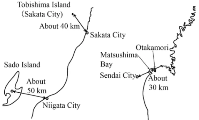
After the invention and development of Yagi-Uda antenna, Uda started research and development of transmitter and re- ceiver in UHF frequency range. He employed the super- regenerative detector circuits for transceivers and Yagi-Uda antenna for transmitting and receiving antennas. In 1929, he succeeded in a communication experiment operating at 600 MHz at a distance of about 30km between Sendai City and Otakamori both in Miyagi Prefecture, Japan as shown in Fig. 4, which was the world’s longest record in UHF radio communication. Figure 5 shows a photograph of a replica of UHF transceiver developed by Uda. He also developed UHF direction finder and these transmitter and receivers were dis- played in the International Exposition held in Belgium in 1930.
He also performed the development of transmitter and receiver in the VHF frequency range. In 1931, he succeeded
Fig. 4 Communication experiment in UHF and VHF frequency ranges.
Fig. 5 Photograph of a replica of UHF transceiver.
in communication experiments at 65 MHz and 53MHz for a distance of about 50 km between Niigata City and Sado Is- land both in Niigata Prefecture. This communication system usingYagi-Uda antennas was put into police radio telephone systems between main-land Japan and Sado Island in 1933.
In 1932, he also succeeded in communication experiments at 38 MHz for 30 km between Sakata City and Tobishima Island. This system was turned into public services of radio wave telecommunication systems between Tobishima Island and main-land Japan in 1933.
4. Self-Complementary Antennas
There is a duality property of the electromagnetic field be- tween electromagnetic fields (E1, H1) in structure #1 and (H2,E2) in structure #2, if all electric walls, magnetic walls, electric currents, and magnetic currents in structure #1 are interchanged for magnetic walls, electric walls, magnetic currents and electric currents in structure #2. In mid-1940s, slot antennas were proposed in Japan, and theoretical in- vestigations on the slot antennas were performed using the duality property of the electromagnetic field, which yields the Babinet’s principle to electromagnetic fields.
Mushiake applied Babinet’s principle in electromag- netic fields to the analysis of a slot antenna having arbitrary shape shown in Fig. 6 (a) and found that the input impedance of the slot antennaZsshown in Fig. 6 (a) is obtained by
Fig. 6 Slot antenna and planar dipole antenna with arbitrary shape.
Zs= (Z0/2)2
Zd , Z0= μ0
ε0 ≈120π (1) whereZd is the input impedance of complementary planar antenna shown in Fig. 6 (b).
Equation (1) had been already obtained in Japan to ob- tain the input impedance of slot antennas earlier than the pa- per of Booker[16]as pointed out by Mushiake[17], and the paper by Asami et al.[18]was a more detailed report of the unpublished earlier paper. However, the structures reported in these papers had been restricted for the thin slot antennas and the thin wire antennas. On the other hand, Eq. (1) de- rived by Mushiake[3]–[5]does not have such limitation and can be applied for slot antennas and planar antennas with arbitrary shape.
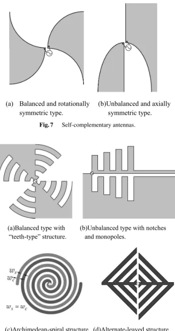
Mushiake also originated the self-complementary structures and discovered that the input impedance of the antennas shown in Fig. 7 and is constant independent of the frequency and given by
Zin=Z0
2 ≈60π[Ω] (2)
since arbitrarily shaped four lines for the boundary of two conducting sheets are exactly identical and the complemen- tary structure in Fig. 7 is exactly the same to the origi- nal structure in Fig. 7 [3]–[5]. Equation. (1) is known as
“Mushiake relationship” and this antenna is called “self- complementary antenna”[19], [20]. The principle of the constant impedance of the self-complementary antennas is called the “principle of self-complementarity”.
The self-complementary antennas are very interest- ing since there is an infinite variety of self-complementary structures as shown in Fig. 8. Although infinite struc- tures are required for the constant impedance of the self- complementary antennas, the structures having teeth or notches and monopoles shown in Fig. 8 (a) and Fig. 8 (b) can realize the constant impedance with a finite conduct- ing plane, because teeth or notches and monopoles radiate electromagnetic power and the truncation effect can be re- duced for the finite structures. Archimedean spiral structure
Fig. 7 Self-complementary antennas.
Fig. 8 Examples of self-complementary structures.
shown in Fig. 8 (c) can also reduce the truncation effect be- cause of the radiation from the spiral arms. Figure 8 (d) is a self-complementary antenna called “alternate-leaved struc- ture” developed by Furuya et al.[21]. Since there is a lot of flexibility of the shape of the self-complementary antennas, it could be possible to obtain antennas having desired gain and/or desired radiation pattern maintaining the constant in- put impedance, e.g. an antenna having desired frequency de- pendence of gain.
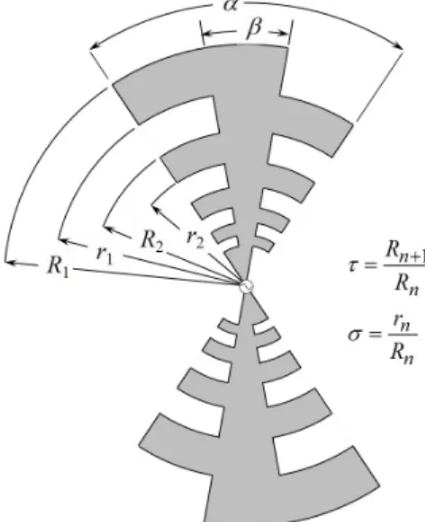
Rumsey and DuHamel found the importance of the principle of self-complementarity[19],[20], and DuHamel and Isbell[22]proposed a modified self-complementary an- tenna with log-periodically spaced teeth as shown in Fig. 9, where the planar antenna is the original self–complementary antenna under the condition ofα+β=π. They showed that the input impedance is constant under the condition that the operating frequency is higher than the frequency at which
Fig. 9 Modified self-complementary antenna with log-periodic shape.
Fig. 10 Log-periodic dipole array (LPDA)[24].
the length of the longest tooth is a quarter wavelength.
Since the planar structures radiate bidirectionally and unidirectional antenna was desired, DuHamel and Ore[23]
tried to deform the structure by folding the planar antenna and obtained a modified self-complementary type antenna called “log-periodic antenna”. They also developed the log- periodic dipole array antenna (LPDA) shown in Fig. 10[23], [24]. The LPDA has been widely used for extremely wide frequency operation in communications and measurements, especially in the EMC measurements.
Mushiake and his colleagues further developed other types of self-complementary antennas, such as rotationally symmetric 4-terminal planar self-complementary antennas, three-dimensional multi-planar self-complementary anten- nas and stacked self-complementary antennas. The details of these antennas are presented in[25],[26].
5. One Wavelength Loop Antenna
Prior to the 1950’s, loop antennas were often used in low frequency ranges and quasi-stationary analysis or equivalent treatment as an infinitesimally small magnetic dipole was employed. However, the characteristics of a loop antenna
Fig. 11 Circular loop antenna.
Fig. 12 Twin loop antennas for UHF TV broadcasting antennas.
changes drastically in the high frequency range and more rigorous treatment was desired. Adachi and Mushiake[7]
performed analyses of loaded and short-circuited loop an- tenna shown in Fig. 11 as a boundary problem based on the Hall´en type integral equation[13]. They also derived a com- pact solution in the first order approximation which is satis- factory for practical purposes[27].
Although the maximum radiation occurs in the direc- tion perpendicular to the axis of loop for the case of elec- trically small antenna, a loop antenna having a conducting wire of one wavelength has maximum radiation in the axial direction and its radiation property is almost the same to that of two element half wavelength dipole array antenna with a spacing of 0.27 wavelength. The directivities of one wave- length and 1.4 wavelength loop antennas in axial direction are about 3.5 dBi and 4.5 dBi, respectively[28], and the di- rectivity of the one wavelength loop antenna with reflector elements is 10.5 dBi.
Because of the high directivity, the one wavelength loop antenna is used as an element of twin loop antenna[29], which has only one driving point but has high gain and wide bandwidth. Four element twin loop antenna and six element
munication systems between small islands and main land Japan invented and developed in Tohoku University were described. Self-complementary antennas invented in To- hoku University, which is the frequency independent an- tenna and yielded log-periodic dipole array antenna, were presented. Analysis and development of the large loop an- tennas including one-wavelength loop antenna is also pre- sented
References
[1] S. Uda, “On the wireless beam of short electric waves,” J. IEE Japan, 450, p. 1128, Dec. 1925 (in Japanese).
[2] H. Yagi and S. Uda, “Projector of the sharpest beam of electric waves,” Proc. Imperial Academy Japan, vol.2, no.2, pp.49–52, Feb.
1926.
[3] Y. Mushiake, “The input impedances of slit antenna,” Joint Conven- tion Record of Tohoku Sections of IEE and IECE of Japan, pp.25–
26, June 1948 (in Japanese).
[4] Y. Mushiake, “The input impedances of slit antennas,” J. IEE Japan, vol.69, no.3, pp.87–88, March 1949 (in Japanese).
[5] S. Uda and Y. Mushiake, “The input impedances of slit antennas,”
Tech. Rep. Tohoku Univ., vol.14, no.1, pp.46–59, Sept. 1949.
[6] S. Uda and Y. Mushiake, Yagi-Uda Antenna, Maruzen, Tokyo, Japan, 1954.
[7] S. Adachi and Y. Mushiake, “Theoretical formulation for circular loop antennas,” Sci. Rep. Research Institute of Electrical Communi- cation, Tohoku Univ., B, vol.9, no.1. pp.9–18, May 1957.
[8] K. Sawaya, “Review of research and development on linear anten- nas,” IEICE Trans. Commun., vol.E86-B, no.3, pp.892–899, March 2003.
[9] S. Uda, “On the wireless beam of short electric waves (I),” J. IEE Japan, 452, pp.273–282, March 1926 (in Japanese).
[10] S. Uda, “On the wireless beam of short electric waves (VII)—A new electric wave projector—,” J. IEE Japan, 467, pp.623–634, June 1927 (in Japanese).
[11] S. Uda, “On the wireless beam of short electric waves (XI) – Propagation of few meter waves–,” J. IEE Japan, 492, pp.755–770, July 1929 (in Japanese).
[12] H. Yagi, “Beam transmission of ultra short waves,” Proc. IRE, vol.16, no.6, pp.715–741, June 1928. (Reprint appeared in Proc.
IEEE, vol.72, no.5, pp.634–645, May 1985).
[13] E. Hall´en, “Theoretical investigations into the transmitting and re- ceiving quality of antennae,” Nova Acta Regiae Scientiarum Up- saliensis IV, vol.11, no.4, pp.3–44, Nov. 1938.
[14] S. Uda, “Radiotelegraphy and radiotelephony on half-meter waves,”
Proc. IRE, vol.18, no.6, pp.1047–1063, June 1930.
[15] S. Uda, B. Obara, I. Arisaka, and T. Seki, “Communication tests on ultra short waves between small islands and main land,” J. IEE Japan, 532, pp.868–872, Nov. 1932 (in Japanese).
[16] H.G. Booker, “Slot aerials and their relation to complementary wire aerials, “ Proc. IEE pt. IIIA, vol.90, no.4, pp.620–629, April 1946.
[17] Y. Mushiake, “A report on Japanese development of antennas: From
[22] R.H. DuHamel and D.E. Isbell, “Broadband logarithmically peri- odic antenna structures,” 1957 IRE National Conv. Record, pt. I, pp.119–128, March 1957.
[23] R.H. DuHamel and F.R. Ore, “Logarithmically periodic antenna de- sign,” 1958 IRE Int. Conv. Record, pt. I, pp.139–151, March 1958.
[24] D.E. Isbell, “Log periodic dipole arrays,” IRE Trans. Antennas Prop- agat., vol.8, no.3, pp.260–267, May 1960.
[25] Y. Mushiake, “Self-complementary antennas,” IEEE Antennas Prop- agat. Magazine, vol.34, no.6, pp.23–39, Dec. 1992.
[26] Y. Mushiake, Self-Complementary Antennas –Principle of Self- Complementarity for Constant Impedance, Springer-Verlag London, 1996.
[27] S. Adachi and Y. Mushiake, “Studies of large circular loop anten- nas,” Sci. Rep. Research Institute of Electrical Communication, To- hoku Univ., B, vol.9, no.2, pp.79–103, Sept. 1957.
[28] R. Johnson, ed., Antenna Engineering Handbook, MacGraw-Hill, ch. 27-3, ch. 29-9, 1993.
[29] K. Endo, Y. Endo, and H. Okamura, “Stacked loop antenna for UHF television broadcasting,” J. Inst. Television Engineers (ITE) Japan, vol.18, no.5, pp.281–287, May 1964 (in Japanese).
Kunio Sawaya received the B.E., M.E. and Ph.D. degrees from Tohoku University, Sendai, Japan, in 1971, 1973 and 1976, respectively. He was a Research Associate, an Associate Profes- sor, and a Professor in the Department of Elec- trical and Communication Engineering at the Tohoku University from 1976 to 2013. He is presently the Vice-Director and a Specially Ap- pointed Professor of Innovation Center for Cre- ation of a Resilient Society, Tohoku University.
His areas of interests are antennas in plasma, an- tennas for mobile communications, theory of scattering and diffraction, antennas for plasma heating, and array antennas. He received the Young Scientists Award in 1981, the Paper Award in 1988, Communications So- ciety Excellent Paper Award in 2006, and Zen-ichi Kiyasu Award in 2009 all from the Institute of Electronics, Information and Communication En- gineers (IEICE). He served as the Chairperson of the Technical Group of Antennas and Propagation of IEICE from 2001 to 2003, the Chairperson of the Organizing and Steering Committees of 2004 International Symposium on Antennas and Propagation (ISAP ’04), the President of the Communi- cations Society of IEICE from 2009 to 2010, and the Chairperson of IEEE Sendai Section from 2012 to 2013. Dr. Sawaya is a Fellow of IEICE, a Fellow of IEEE, and a member of the Institute of Image Information and Television Engineers of Japan.