SUMMARY Recent progress in research on the finite element method (FEM) for optical waveguide design and analysis is reviewed, focusing on the author’s works. After briefly reviewing fundamentals of FEM such as a theoretical framework, a conventional nodal element, a newly developed edge element to eliminate nonphysical, spurious solutions, and a perfectly matched layer to avoid undesirable reflections from computational win- dow edges, various FEM techniques for a guided-mode analysis, a beam propagation analysis, and a waveguide discontinuity analysis are described.
Some design examples are introduced, including current research activities on multi-core fibers.
key words: finite element method, beam propagation method, spurious solutions, fiber optics, nanophotonics
1. Introduction
Recent advances in the field of guided-wave optics, such as fiber optics and nanophotonics, have included the intro- duction of arbitrarily-shaped optical waveguides which, in many cases, also happened to be inhomogeneous, dissipa- tive, anisotropic, and/or nonlinear. Most of such cases of waveguide arbitrariness do not lend themselves to analytical solutions and therefore, computational tools for modeling and simulation are essential for successful design, optimiza- tion, and realization of high-performance optical waveg- uides. For this purpose, various numerical techniques have been developed. In particular, the finite element method (FEM) is a powerful and efficient tool for the most general guided-wave problems. Its use in both the research commu- nity and the commercial sector is extensive, and indeed it could be said that without it many optical waveguide prob- lems would be incapable of solution.
Over the last few decades, the author and his co- workers have developed new numerical formulations and techniques based on FEM for design and analysis of opti- cal fibers and nanophotonic devices/circuits that have con- tributed to the advancement of computational photonics. In this paper, recent progress in FEM research is reviewed, fo- cusing on the author’s works. After briefly reviewing fun- damentals of FEM such as a theoretical framework, a con- ventional nodal element, a newly developed edge element to eliminate nonphysical, spurious solutions, and a perfectly matched layer (PML) to avoid undesirable reflections from computational window edges, various FEM techniques for a guided-mode analysis, a beam propagation analysis, and
Manuscript received September 19, 2013.
†The author is with Hokkaido University Career Center, Sapporo-shi, 060-0808 Japan.
a) E-mail: [email protected] DOI: 10.1587/transele.E97.C.625
a waveguide discontinuity analysis are described. Some de- sign examples are introduced, including current research ac- tivities on multi-core fibers (MCFs).
2. Fundamentals of Finite Element Method
2.1 Theoretical Framework
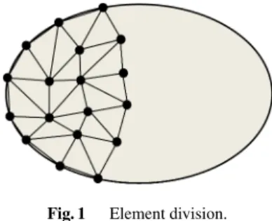
In FEM, instead of differential equations for the system under consideration, corresponding functionals (variational expressions) to which a variational principle is applied are set up, where the region of interest is divided into the so- called elements as shown in Fig. 1. In FEM, an equivalent discretized model for each element is considered and then, all the element contributions to the system are assembled. In other words, FEM can be considered a subclass of the Ritz method, in which piecewise defined polynomial functions are used for trial functions and infinite degrees of freedom of the system are discretized or replaced by a finite number of unknown parameters.
Elements can have various shapes, allowing the use of a non-uniform mesh. Therefore, FEM is suitable for prob- lems with very steep variations of fields. Furthermore, this approach can be easily adopted into inhomogeneous and anisotropic problems, and it is possible to systematically increase the accuracy of solutions obtained, as necessary.
In addition, FEM can be established not only by the vari- ational method but also by the Galerkin method which is a weighted residual method. Therefore, FEM may be ap- plicable to lossy and/or leaky optical waveguides, where a variational principle does not exist or cannot be identified.
2.2 Nodal and Edge Elements
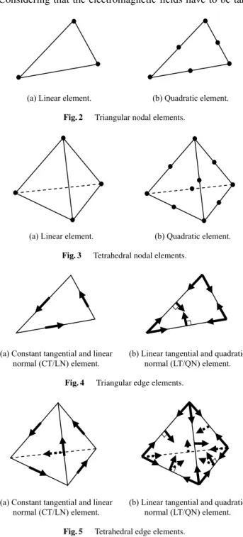
Various elements are available in FEM. Figures 2 and 3 show conventional nodal elements. Triangular and tetrahe- dral elements are utilized for two-dimensional and three-
Fig. 1 Element division.
Copyright c⃝2014 The Institute of Electronics, Information and Communication Engineers
dimensional problems, respectively. The lowest-order or linear element employs the first-order polynomial. The quadratic element, on the other hand, employs the second- order polynomial.
The most serious difficulty in applying FEM to electro- magnetic wave problems was the appearance of nonphysi- cal, spurious solutions. Consequently, the development of a method to suppress or eliminate such spurious solutions was pressingly needed.
The spurious solutions can be characterized as
∇ ×Φ=0 (1)
withΦbeing the electric field Eor the magnetic fieldH.
Considering that the electromagnetic fields have to be tan-
(a) Linear element. (b) Quadratic element.
Fig. 2 Triangular nodal elements.
(a) Linear element. (b) Quadratic element.
Fig. 3 Tetrahedral nodal elements.
(a) Constant tangential and linear normal (CT/LN) element.
(b) Linear tangential and quadratic normal (LT/QN) element.
Fig. 4 Triangular edge elements.
(a) Constant tangential and linear normal (CT/LN) element.
(b) Linear tangential and quadratic normal (LT/QN) element.
Fig. 5 Tetrahedral edge elements.
gentially continuous across material interfaces and eliminat- ing some of null-space degrees of freedom corresponding to irrotational, spurious fields expressed as Eq. (1) from trial fields, the so-called edge elements as shown in Figs. 4 and 5 have been developed [1], [2].
The lowest-order triangular and tetrahedral edge ele- ments, which employ three and six variables, respectively, are based on constant tangential and linear normal (CT/LN) vector basis functions. The tangential component of a par- ticular CT/LN basis function is constant along one edge of triangle and tetrahedron, and is zero along the other edges, while the normal component is a linear function along all edges. The higher-order triangular and tetrahedral edge el- ements, which employ eight and twenty variables, respec- tively, are based on linear tangential and quadratic normal (LT/QN) vector basis functions.
2.3 Perfectly Matched Layer
When simulating optical waveguide devices and/or circuits, in order to reduce spurious reflections from the compu- tational window edges, the use of appropriate absorbing boundary conditions is indispensable. For this purpose, the PML condition [3] was developed. Unfortunately, since the earlier PML technique involves a modification of Maxwell’s equations based on the splitting of field components into two subcomponents, these non-Maxwellian equations do not have a desirable form for the FEM formulations. Re- cently, the so-called anisotropic PML, which does not in- volve the field splitting, was developed [4] and has been widely used for mesh truncation in the FEM analysis.
We consider a three-dimensional domain surrounded by PML regions 1 to 7 with thickness di(i=1,2,3) as shown in Fig. 6. A non-PML region has dimensions a, b, andcin the x, y, andz directions, respectively. Using the anisotropic PML, the PML permittivity and permeabil- ity tensors are written as
[ε]PML=sxsysz[S][ε][S] (2a) [µ]PML=sxsysz[S][µ][S] (2b) with
[S]=
1/sx 0 0
0 1/sy 0 0 0 1/sz
(3)
where [ε] and[µ]
are, respectively, the permittivity and per- meability tensors of the original PML regions. PML param- eterssx,sy, szare listed in Table 1, where the values ofsiin Table 1 are real for bounded-field problems as
si=1+αi (4)
and they are complex for unbounded-field problems as
si=1−jαi (5)
Attenuation of the electromagnetic field in PML regions can be controlled by choosing appropriate values ofαiand we
Fig. 6 Computational domain surrounded by perfectly matched layers.
Table 1 Perfectrly matched layer (PML) parameters.
PML PML region
parameter 1 2 3 4 5 6 7
sx s1 1 1 1 s1 s1 s1
sy 1 s2 1 s2 1 s2 s2
sz 1 1 s3 s3 s3 1 s3
For two-dimensional problems, which are uniform in thex,y, andz directions,sx,sy, andszare set to 1, respectively.
assume parabolic profiles ofαias
αi=αi,MAX(ρ/di)2 (6) whereρis the distance from the beginning of PML and the subscript “max” denotes the maximum value.
3. Guided-mode Analysis
3.1 Straight Waveguide Analysis
Although a formulation based on a single scalar quantity is inadequate for the general guided-mode analysis, the use- ful approximation can be found for weakly guiding struc- tures and the so-called approximate scalar FEM has been developed [5], [6]. In the approximate scalar FEM, conven- tional nodal elements can be used and spurious solutions do not occur. However, to rigorously evaluate guided-modes in strongly guiding structures such as high-index contrast (HIC) waveguides, photonic crystal (PC or PhC) waveg- uides, hole-assisted fibers (HAFs), and photonic crystal fibers (PCFs) which are grouped into holey fibers (HFs) with index-guiding effect and photonic band-gap fibers (PBGFs) with photonic band-gap effect, a full vector analysis is nec- essary, and different types of full vector FEM have been developed. Here, the electromagnetic field with a time (t) dependence of the form exp (jωt) is expressed as
Φ=ϕ(x, y) exp[j(ωt−βz)] (7) wherezis the propagation direction, ω is the angular fre- quency, andβis the propagation constant.
Of the various formulations, the FEM using full vector electric or magnetic field is quite suitable for a wide range
Fig. 7 Curvilinear hybrid edge/nodal elements.
of practical, complicated problems. The most serious prob- lem associated with this approach is the appearance of spuri- ous solutions. The penalty function method (PFM) has been widely used to cure this problem [7]–[9], but in this tech- nique, an arbitrary positive constant, called the penalty coef- ficient, is involved and the accuracy of solutions depends on its magnitude. Furthermore, in PMF, the propagation con- stant is first given as an input datum, and subsequently the operating angular frequency or the operating wavelength is obtained as a solution.
In order to overcome these issues in PFM, edge ele- ments have been introduced into the guided-mode analysis of a waveguide with arbitrary cross section in thexy(trans- verse) plane [10]–[12], and curvilinear hybrid edge/nodal elements with triangular shape as shown in Fig. 7 were de- veloped [12].
Figure 7(a) shows the lowest-order hybrid element which is composed of a CT/LN edge element with three variables for transverse fields and a linear nodal element with three variables for axial fields [10]. Figure 7(b) shows the higher-order hybrid element which is composed of a LN/QT edge element with eight variables and a quadratic nodal element with six axial variables. Removing ϕt7 and ϕt8from the LT/QN element, we can obtain another higher- order hybrid element composed of a linear tangential and linear normal (LT/LN) element and a quadratic nodal ele- ment [11]. Curvilinear hybrid elements can give faster con- vergence than rectilinear hybrid elements and when using a curvilinear hybrid element composed of a LN/QT edge el- ement and a quadratic nodal element, significantly fastest convergence is obtained, irrespective of values of the oper- ating wavelength (input datum) [12].
3.2 Curved Waveguide Analysis
A curvilinear hybrid edge/nodal element has been used not only for a straight optical waveguide analysis but also for a curved optical waveguide analysis. In [13], a full vector FEM was formulated in a local cylindrical coordinate sys- tem and an anisotropic PML was implemented to the com- putational window edges.
Recently, using this approach, a bend-insensitive and effectively single-moded all-solid PBGF (AS-PBGF) with heterostructured cladding was designed and fabricated [14].
Figures 8(a), (b), and (c) show a typical AS-PBGF (uni- form structure), a segmented cladding structure, and a wind-
Fig. 8 All-solid photonic band-gap fiber with heterostructured cladding [14].
mill structure, respectively. In Fig. 9, the bending losses as a function of bend radius at 1550-nm wavelength are pre- sented for these structures. We can see that the bending loss of the windmill structure is effectively low and com- patible to that of the multi-moded 7-cell-core uniform struc- ture. Therefore, the windmill structure based on the het- erostructured cladding exhibits both low bending losses and low confinement losses while keeping single-mode opera- tion, which is one of the issues in a solid core PBGF.
4. Beam Propagation Analysis
4.1 Beam Propagation Method
The beam propagation method (BPM) is at present the most widely used for the study of light propagation in longitu- dinally varying waveguides. Under the slowly varying en- velope approximation (SVEA), the electromagnetic field is expressed as
Φ=ϕ(x, y,z) exp[j(ωt−β0z) ] (8) whereϕis the slowly varying complex amplitude andβ0is the reference propagation constant which can be renewed at every propagation step.
In the BPM based on FEM (FE-BPM), the field in the transverse (xy) plane is discretized with FEM and the Crank-Nicholson algorithm is applied to the propagation
Fig. 9 Bending losses as a function of bend radius for 7-cell-core uni- form, segmented cladding, and windmill structures [14].
(z) direction. It is possible to use non-uniform finite ele- ment meshes and these meshes can be adaptively updated along the propagation direction so that computational effi- ciency can be improved without degrading numerical accu- racy. Simple and efficient mesh generation algorithms for an approximate scalar FE-BPM analysis [15] and a full vector FE-BPM analysis [16] have already been developed.
One of the key issues in implementing FE-BPM to study light propagation in a finite spatial domain is the boundary condition at the computational window edges.
Recently, an anisotropic PML has been effectively imple- mented not only to a two-dimensional FE-BPM (2D-FE- BPM) [17] for planar optical waveguides but also to an ap- proximate scalar three-dimensional FE-BPM (3D-FE-BPM) [18] and a full vector 3D-FE-BPM [19] for arbitrarily- shaped optical waveguides.
Recently, using the approximate scalar 3D-FE-BPM, a low-loss and broadband mode (de)multiplexer based on a directional coupler (DC) and a wavelength insensitive cou- pler (WINC) as shown in Fig. 10 was designed and fabri- cated for mode-division multiplexing (MDM) transmission [20], where a silica-based planar lightwave circuit (PLC) is used. Figures 11(a) and (b) show, respectively, the numeri- cal and the experimental results of the wavelength depen- dence of the transmission of the mode (de)multiplexer at port 4 when the LP01 mode is input into port 1 or port 2.
The inset images in Fig. 11(b) show near field patterns mea- sured at wavelengths of 1060 nm, 1310 nm, and 1550 nm.
Excepting the radiation loss due to the mode field diame- ter mismatch between the input/output fiber and the PLC waveguide, the experimental results agree well with the nu- merical results and it is confirmed that the broadband mode conversion from the LP01mode to the LP11mode is realized by using the WINC-based mode multiplexer.
4.2 Imaginary Distance Beam Propagation Method It should be noted that the so-called imaginary distance BPM (ID-BPM) has been reported as an analysis method of guided modes. In ID-BPM, the propagation direction is selected along the imaginary axis and selecting the appropri- ate propagation step size, we can extract the specific guided mode from the initial input field. There are a number of
Fig. 10 Structures of mode (de)multiplexers [20].
Fig. 11 Wavelength dependence of the transmission of mode (de) multi- plexers at port 4 [20].
versions of ID-BPM. In the ID-BPM based on FEM (FE- ID-BPM), to evaluate propagation losses of leaky modes, an anisotropic PML is employed as a boundary condition at computational window edges. Both an approximate scalar FE-ID-BPM [21] with conventional nodal elements and a full vector FE-ID-BPM [22] with hybrid edge/nodal ele- ments have already been developed.
In particular, the full vector FE-ID-BPM has been ef- fectively applied to characterizing various PCFs such as HFs [23],[24] and PBGFs [25]. To model PCFs accurately, es- pecially with large air holes or high-index rods, it is cru- cial to use a full vector model. FEM is useful not only for idealized-model simulations but also for realistic-model simulations based on actual fiber structures [26]. A curvi- linear hybrid element composed of a LN/QT edge element and a quadratic nodal element shown in Fig. 7(b) is useful for accurately modeling the curved boundaries of air holes
and high-index rods.
Here, we consider a fabricated dispersion compensat- ing PCF (DCPCF) [27] as shown in Fig. 12(a), which is based on a concentric dual core refractive index profile, where the ring core (second air-hole ring from the central core) is formed by reducing the air-hole size. The diameter of outer cladding air-holes is tailored to control the disper- sion slope as well as the confinement loss. The air-holes surrounding the inner core are not circular in shape and two opposing holes are smaller than the other four. This makes this fiber highly birefringent and the two fundamental core modes become polarization-split. One mode will be polar- ized along the slow-axis and the other along the fast-axis.
Figure 12(b) shows the finite element mesh used in the full vector FE-ID-BPM simulation [28], where the number of hybrid edge/nodal elements is 47,000 and the number of the unknowns is 327,000. Anisotropic PML boundaries are ap- plied to enable the calculation of the precise leakage loss of the fiber. Figure 12(c) shows the electric field distribution of the slow-axis mode at 1550-nm wavelength [28]. The mode is well confined to the inner core. The effective area of the realistic fiber was calculated to be 1.81 µm2 at 1550 nm, which is slightly smaller than the value of effective area of 2.0µm2of the fabricated DCPCF [27].
Recently, using the full vector FE-ID-BPM, a bending- insensitive single-mode HAF with two air-hole rings was designed and fabricated [29] as shown in Fig. 13. A circular bend structure was replaced by a straight fiber with equiva- lent refractive index and an anisotropic PML was used along the radiation direction. Figure 14 shows the theoretical and experimental bending loss of HAF with two air-hole rings as a function of bending radius at 1550-nm wavelength. We can see that the bending loss of the HAF is much less than that of the standard single-mode fiber (SMF), especially for small bending radius. The theoretical results are in good agreement with the experimental results.
5. Waveguide Discontinuity Analysis
5.1 Frequency-domain Analysis
BPM assumes only the forward propagating waves and therefore, it is difficult to take into account backward reflec-
Fig. 12 Realistic model simulation.
tion from the waveguide discontinuity region. In the waveg- uide discontinuity analysis performed in the frequency do- main, the electromagnetic field is expressed as
Φ=ϕ(x, y,z) exp (jωt) (9)
The frequency-domain FEM (FD-FEM) has been widely used for the waveguide discontinuity problems. In the earlier works, FEM was applied to the finite discontinu- ity region and the mode expansion technique was used for representing infinite uniform waveguides connected to the input and output ports. However, it is difficult and cumber- some to construct the mode expansion boundary condition by taking all the existing modes into account.
Recently, by replacing the input and output ports by anisotropic PML absorbers, the FD-FEM without mode expansion technique has been developed not only for 2D
Fig. 13 Single-mode hole-assisted fiber with two air-hole rings [29].
Fig. 14 Bending loss as a function of bending radius at 1550 nm [29].
waveguide discontinuity problems [30] but also for 3D waveguide discontinuity problems [31]. In 2D-FD-FEM, a triangular nodal element shown in Fig. 2(b) is used and in 3D-FD-FEM, on the other hand, a tetrahedral edge element shown in Fig. 5(b) is used.
More recently, using the 2D-FD-FEM, a compact two- mode multi/demultiplexer (TM-MUX) consisting of mul- timode interference (MMI) waveguides and a wavelength- insensitive phase shifter (PS) was designed for MDM trans- mission [32]. A silicon-on-insulator (SOI) wafer is assumed and the 3D waveguide structure is replaced by the equivalent 2D waveguide structure with the help of the effective index method. Figure 15(a) shows a schematic drawing of TM- MUX which includes MMI-based mode converter-splitter (MCS), PS with butterfly-shape tapered waveguide struc- ture, and MMI-based 3-dB coupler. Figure 15(b) shows the structure of TM-MUX. Ports 1, 3, and 6 are placed to pre- vent the reflections at the end of MMI waveguides. Fig- ures 16(a) and (b) show the field distributions of TM-MUX at 1550-nm wavelength for the cases of inputting the fun- damental mode and of the first higher-order mode, respec- tively. When the fundamental mode is input, the fundamen- tal mode is output into port 5. When the first higher-order mode is input, on the other hand, the first higher-order mode is converted into the fundamental mode and is output into port 4. In both cases, little lights are output into the other ports. Therefore, the TM-MUX works as a mode demulti- plexer when input port is port 2.
5.2 Time-domain Analysis
Usual BPMs are inadequate for the waveguide discontinuity analysis. Recently, under the condition that the modulation frequency is much lower than the career frequency, a sim-
Fig. 15 Compact two-mode multi/demultiplexer [32].
Fig. 16 Field distributions in two-mode multi/demultiplexer [32].
ple and efficient propagation algorithm was developed and is called the time-domain BPM (TD-BPM). In this algorithm, the electromagnetic field is expressed as
Φ=ϕ(x, y,z,t) exp(jω0t) (10) whereϕis the modulated envelope andω0is the career cen- ter angular frequency.
In the TD-BPM based on FEM (FE-TD-BPM) with anisotropic PMLs [33], the computational spatial domain is discretized with FEM and the Crank-Nicholson algorithm is applied to the time (t) domain. The FE-TD-BPM can tackle waveguide discontinuity problems and a high-performance PML was also developed for PC waveguide discontinuity problems [34]. Recently, a MUX/DEMUX based on PC couplers was proposed and its wavelength demultiplexing properties were investigated by using the FE-TD-BPM [35].
Here, we consider a sharp 90◦bend based on PCs com- posed of dielectric pillars in air on square array with lattice constant of 0.580µm, where the radius and the refractive index are 0.104µm and 3.4, respectively [36]. In this struc- ture, almost 100% transmission could be achieved. Fig- ure 17 shows the electric field patterns for the input pulse of career center wavelength of 1.45 µm, where the time step size is taken as 1.0 fs [33]. In the well-known finite- difference time-domain (FDTD) method, very small time step size must be used, compared with FE-TD-BPM, be- cause in FDTD, both the carrier and the modulated envelope are included in the wave propagator. In Fig. 17, the reflected fields from the 90◦bend can be hardly observed.
6. Multi-core Fiber Design and Analysis
In current optical fiber transmission systems, transmis- sion capacity is rapidly approaching its fundamental limit.
Therefore, an innovative technology is expected to break the
limit. In order to overcome this issue, space division mul- tiplexing (SDM) and MDM technologies based on uncou- pled MCFs [37], coupled MCFs [38], and few-mode fibers (FMFs) have been investigated actively [39].
The most important issue peculiar to uncoupled MCFs is to reduce the intercore crosstalk. Recently, to estimate the intercore crosstalk in bent and twisted MCFs, a coupled- mode theory (CMT) and a coupled-power theory (CPT) have been newly formulated [40], and an analytical expres- sion for estimating the average intercore crosstalk was also found, resulting in no need for heavy numerical compu- tations [41]. Propagation characteristics of each core and coupling coefficients between two cores in a straight MCF necessary for the solutions of CMT and CPT are accurately evaluated with the full vector FE-ID-BPM which can treat measured refractive-index profiles [42].
Here, we consider a quasi-homogeneous 7-core fiber with nearly identical cores [43] as shown in Fig. 18. Fig- ure 19 shows the bending-diameter dependence of crosstalk from center core 1 to outer cores 2 to 7 calculated with the analytical expression [41], where the dotted line, solid line, dashed line, and dashed and dotted line stand for the cor- relation lengths of 10 mm, 50 mm, 100 mm, and 500 mm, respectively. The theoretical results with correlation length of 50 mm are in good agreement with the experimental re- sults [43].
In order to realize low crosstalk and a dense core ar- rangement simultaneously in MCFs, various trench-assisted MCFs (TA-MCFs) such as 7-core fiber with one-pitch lay- out [44], 10-core fiber with two-pitch layout [45], 12-core fiber with one-ring layout [46], and 12-core fiber with two- ring layout [47] have been developed as shown in Fig. 20.
The full vector FE-ID-BPM and the CPT have been effec- tively utilized for design and analysis of these TA-MCFs.
Fig. 17 Electric field patterns in photonic crystal bend [33].
Fig. 18 Quasi-homogeneous multi-core fiber [43].
Most recently, the transmission experiment with the record capacity of 1.01 Pb/s over the one-ring 12-core TA-MCF has been reported [48]
In MDM based on coupled MCFs and FMFs, a mode MUX/DEMUX is needed for exciting and separating dif- ferent modes [38]. Recently, using the full vector FE-ID- BPM for a guided-mode analysis and the full vector FE- BPM for a beam propagation analysis, a fiber-based 1×4 mode MUX/DEMUX was designed for the coupled MCF based MDM [49].
Fig. 19 Crosstalk from center core 1 to outer cores 2 to 7 [41].
Fig. 20 Trench-assisted multi-core fibers.
7. Conclusion
Recent progress in FEM research for optical waveguide de- sign and analysis was reviewed, focusing on the author’s works. After briefly reviewing fundamentals of FEM such as a theoretical framework, a conventional nodal element,
cal waveguide structures with electro-optic effect [50], [51], magneto-optic effect [52],[53], acousto-optic effect [54]–
[56], nonlinear effect causing second harmonic generation [57], and instantaneous Kerr-type nonlinear effect [58]–
[60].
It is the author’s wish that this paper will contribute to the dissemination and development of computational pho- tonics in future.
Acknowledgments
The author would like to express his gratitude to Dr. T.
Shibata, Chair of the Editorial Committee for the Special Section on “Recent Advances in Simulation Techniques and Their Applications for Electronics” planned in the IEICE Transactions on Electronics, and to the Committee Mem- bers for their encouragement. The author also would like to thank Prof. K. Saitoh of Hokkaido University for helpful discussions. His thanks are also extended to students who worked in his laboratory at Hokkaido University for their Ph.D., M. S., and B. S. theses.
References
[1] J. F. Lee, D. K. Sun, and Z. J. Cendez, “Tangential vector finite elements for electromagnetic field computation,” IEEE Trans. Magn.
vol. 27, no. 5, pp. 4032–4035, Sept. 1991.
[2] A. F. Peterson, “Vector finite element formulation for scattering from two-dimensional heterogeneous bodies,” IEEE Trans. Anten- nas Propag., vol. 42, no. 3, pp. 357–365, Mar. 1994.
[3] J. P. Berenger, “A perfectly matched layer for the absorption of elec- tromagnetic waves,” J. Comput. Phys., vol. 114, no. 2, pp. 185–200, Oct. 1994.
[4] F. L. Teixeira and W. C. Chew, “General closed-form PML consti- tutive tensors to match arbitrary bianisotropic and dispersive linear media,” IEEE Microwave Guided Wave Lett., vol. 8, no. 6, pp. 223–
225, June 1998.
[5] M. Koshiba, K. Hayata, and M. Suzuki, “Approximate scalar finite- element analysis of anisotropic optical waveguides,” Electron. Lett., vol. 18, no. 10, pp. 411–413, May 1982.
[6] M. Koshiba, K. Hayata, and M. Suzuki, “Approximate scalar finite- element analysis of anisotropic optical waveguides with off-diagonal elements in a permittivity tensor,” IEEE Trans. Microw. Theory Tech., vol. MTT-32, no. 6, pp. 587–593, June 1984.
[7] M. Koshiba, K. Hayata, and M. Suzuki, “Vectorial finite-element method without spurious solutions for dielectric waveguide prob- lems,” Electron. Lett., vol. 20, no. 10, pp. 409–410, May 1984.
[8] M. Koshiba, K. Hayata, and M. Suzuki, “Improved finite-element formulation in terms of the magnetic field vector for dielectric waveguides,” IEEE Trans. Microw. Theory Tech., vol. MTT-33, no. 3, pp. 227–233, Mar. 1985.
[9] M. Koshiba, K. Hayata, and M. Suzuki, “Finite-element solution of anisotropic waveguides with arbitrary tensor permittivity,” J. Light- wave Technol., vol. LT-4, no. 2, pp. 121–126, Feb. 1986.
Technol., vol. 18, no. 5, pp. 737–743, May 2000.
[13] K. Kakihara, N. Kono, K. Saitoh, and M. Koshiba, “Full-vectorial finite element method in a cylindrical coordinate system for loss analysis of photonic wire bends,” Opt. Express, vol. 14, no. 23, pp. 11128–11141, Nov. 2006.
[14] T. Murao, K. Saitoh, T. Taru, T. Nagashima, K. Maeda, T. Sasaki, and M. Koshiba, “Bend-insensitive and effectively single-moded all- solid photonic bandgap fibers with heterostructured cladding,” Eu- ropean Conference on Optical Communication (ECOC 2009), 2.1.4, Vienna, Austria, Sept. 2009.
[15] Y. Tsuji and M. Koshiba, “Simple and efficient adaptive mesh gen- eration for approximate scalar guided-mode and beam-propagation solutions,” IEICE Trans. Electron., vol. E81-C, no. 12, pp. 1814–
1820, Dec. 1998.
[16] Y. Tsuji and M. Koshiba, “Adaptive mesh generation for full- vectorial guided-mode and beam-propagation solutions,” IEEE J.
Selected Top. Quantum Electron., vol. 6, no. 1, pp. 163–169, Jan.- Feb. 2000.
[17] M. Koshiba, Y. Tsuji, and M. Hikari, “Finite element beam propa- gation method with perfectly matched layer boundary conditions,”
IEEE Trans. Magn., vol. 35, no. 3, pp. 1482–1485, May 1999.
[18] K. Saitoh and M. Koshiba, “Approximate scalar finite-element beam-propagation method with perfectly matched layers for anisotropic optical waveguides,” J. Lightwave Technol., vol. 19, no. 5, pp. 786–792, May 2001.
[19] K. Saitoh and M. Koshiba, “Full-vectorial finite element beam prop- agation method with perfectly matched layers for anisotropic opti- cal waveguides,” J. Lightwave Technol., vol. 19, no. 3, pp. 405–413, Mar. 2001.
[20] Uematsu, K. Saitoh, N. Hanzawa, T. Sakamoto, T. Matsui, K. Tsu- jikawa, and M. Koshiba, “Low-loss and broadband PLC-type mode (de)multiplexer for mode-division multiplexing transmission,” Opti- cal Fiber Communication Conference (OFC 2013), OTh1B.5, Ana- heim, USA, Mar. 2013.
[21] Y. Tsuji and M. Koshiba, “Guided-mode and leaky-mode analysis by imaginary distance beam propagation method based on finite el- ement scheme,” J. Lightwave Technol., vol. 18, no. 4, pp. 618–623, Apr. 2000.
[22] K. Saitoh and M. Koshiba, “Full-vectorial imaginary-distance beam propagation method based on a finite element scheme: Application to photonic crystal fibers,” IEEE J. Quantum Electron., vol. 38, no. 7, pp. 927–933, July 2002.
[23] M. Koshiba, “Full-vector analysis of photonic crystal fibers using the finite element method,” IEICE Trans. Electron., vol. E85-C, no. 4, pp. 881–888, Apr. 2002 (invited paper).
[24] K. Saitoh and M. Koshiba, “Numerical modeling of photonic crystal fibers,” J. Lightwave Technol., vol. 23, no. 11, pp. 3580–3590, Nov.
2005 (invited paper).
[25] K. Saitoh, T. Murao, L. Rosa, and M. Koshiba, “Effective area limit of large-mode-area solid-core photonic bandgap fibers for fiber laser applications,” Opt. Fiber Technol., vol. 16, no. 6, pp. 409–418, Dec.
2010 (invited paper).
[26] M. Koshiba and K. Saitoh, “Finite-element analysis of birefringence and dispersion properties in actual and idealized holey-fiber struc- tures,” Appl. Opt., vol. 42, no. 31, pp. 6267–6275, Nov. 2003.
[27] P. J. Roberts, B. J. Mangan, H. Sabert, F. Couny, T. A. Birks, J. C.
Knight, and P. St.J. Russell, “Control of dispersion in photonic crys- tal fibers,” J. Opt. Fiber Commun. Rep., vol. 2, no. 5, pp. 435–461,
Nov. 2005.
[28] S. K. Varshney, K. Saitoh, M. Koshiba, and P. J. Roberts, “Analysis of a realistic and idealized dispersion compensating photonic crystal fiber Raman amplifier,” Opt. Fiber Technol., vol. 13, no. 2, pp. 174–
179, Apr. 2007.
[29] Y. Tsuchida, K. Saitoh, and M. Koshiba, “Design and characteri- zation of single-mode holey fibers with low bending losses,” Opt.
Express, vol. 13, no. 12, pp. 4770–4779, June 2005.
[30] Y. Tsuji and M. Koshiba, “Finite element method using port trun- cation by perfectly matched layer boundary conditions for optical waveguide discontinuity problems,” J. Lightwave Technol., vol. 20, no. 3, pp. 463–468, Mar. 2002.
[31] Y. Ishizaka, Y. Kawaguchi, K. Saitoh, and M. Koshiba, “Three- dimensional finite-element solutions for crossing slot-waveguides with finite core-height,” J. Lightwave Technology, vol. 30, no. 21, pp. 3394–3400, Nov. 2012.
[32] T. Uematsu, Y. Ishizaka, Y. Kawaguchi, K. Saitoh, and M Koshiba,
“Design of a compact two-mode multi/demultiplexer consisting of multi-mode interference waveguides and a wavelength insensitive phase shifter for mode-division multiplexing transmission,” J. Light- wave Technol., vol. 30, no. 15, pp. 2421–2426, Aug. 2012.
[33] M. Koshiba, Y. Tsuji, and M. Hikari, “Time-domain beam prop- agation method and its application to photonic crystal circuits,” J.
Lightwave Technol., vol. 18, no. 1, pp. 102–110, Jan. 2000.
[34] M. Koshiba, Y. Tsuji, and S. Sasaki, “High-performance absorbing boundary conditions for photonic crystal waveguide simulations,”
IEEE Microwave Wireless Compon. Lett., vol. 11, no. 4, pp. 152–
154, Apr. 2001.
[35] M. Koshiba, “Wavelength division multiplexing and demultiplexing with photonic crystal waveguide couplers,” J. Lightwave Technol., vol. 19, no. 12, pp. 1970–1975, Dec. 2001.
[36] A. Mekis, J. C. Chen, I. Kurland, S. Fan, P. R. Villeneuve, and J. D.
Joannopoulos, “High transmission through sharp bends in photonic crystal waveguides,” Phys. Rev. Lett., vol. 77, no. 18, pp. 3787–
3790, Oct. 1996.
[37] M. Koshiba, K. Saitoh, and Y. Kokubun, “Heterogeneous multi-core fibers: Proposal and design principle,” IEICE Electron. Express, vol. 6, no. 2, pp. 98–103, Jan. 2009.
[38] Y. Kokubun and M. Koshiba, “Novel multi-core fibers for mode divi- sion multiplexing: Proposal and design principle,” IEICE Electron.
Express, vol. 6, no. 8, pp. 522–528, Apr. 2009.
[39] T. Morioka, Y. Awaji, R. Ryf, P. Winzer, D. Richardson, and F. Po- letti, “Enhancing optical communications with brand new fibers,”
IEEE Commun. Magazine, vol. 50, no. 2, pp. S31–S42, Feb. 2012.
[40] M. Koshiba, K. Saitoh, K. Takenaga, and S. Matsuo, “Multi-core fiber design and analysis: Coupled-mode theory and coupled-power theory,” Opt. Express, vol. 19, no. 26, pp. B102–B111, Dec. 2011.
[41] M. Koshiba, K. Saitoh, K. Takenaga, and S. Matsuo, “Analytical expression of average power-coupling coefficients for estimating in- tercore crosstalk in multicore fibers,” IEEE Photon. J., vol. 4, no. 5, pp. 1987–1995, Oct. 2012.
[42] K. Saitoh, M. Koshiba, K. Takenaga, and S. Matsuo, “Crosstalk and core density in uncoupled multi-core fibers,” IEEE Photon. Technol.
Lett., vol. 24, no. 21, pp. 1898–1901, Nov. 2012.
[43] S. Matsuo, K. Takenaga, Y. Arakawa, Y. Sasaki, S. Tanigawa, K.
Saitoh, and M. Koshiba, “Crosstalk behavior of cores in multi-core fiber under bent condition,” IEICE Electron. Express, vol. 8, no. 6, pp. 385–390, Mar. 2011.
[44] K. Takenaga, Y. Arakawa, Y. Sasaki, S. Tanigawa, S. Matsuo, K.
Saitoh, and M. Koshiba, “A large effective area multi-core fiber with an optimized cladding thickness,” Opt. Express, vol. 19, no. 26, pp.
B543-B550, Dec. 2011.
[45] S. Matsuo, K. Takenaga, Y. Arakawa, Y. Sasaki, S. Tanigawa, K.
Saitoh, and M. Koshiba, “Large-effective-area ten-core fiber with cladding diameter of about 200µm,” Opt. Lett., vol. 36, no. 23, pp. 4626–4628, Dec. 2011.
[46] S. Matsuo, Y. Sasaki, T. Akamatsu, I. Ishida, K. Takenaga, K.
Okuyama, K. Saitoh, and M. Koshiba, “12-core fiber with one ring structure for extremely large capacity transmission,” Opt. Express, vol. 20, no. 27, pp. 28398–28408, Dec. 2012.
[47] A. Sano, H. Takara, T. Kobayashi, H. Kawakami, H. Kishikawa, T.
Nakagawa, Y. Miyamoto, Y. Abe, H. Ono, K. Shikama, M. Nagatani, T. Mori, Y. Sasaki, I. Ishida, K. Takenaga, S. Matsuo, K. Saitoh, M.
Koshiba, M. Yamada, H. Masuda, and T. Morioka, “409-Tb/s+409- Tb/s crosstalk suppressed bidirectional MCF transmission over 450 km using propagation-direction interleaving,” Opt. Express, vol. 21, no. 14, pp. 16777–16783, July 2013.
[48] H. Takara, A. Sano, T. Kobayashi, H. Kubota, H. Kawakami, A.
Matsuura, Y. Miyamoto, Y. Abe, H. Ono, K. Shikama, Y. Goto, K.
Tsujikawa, Y. Sasaki, I. Ishida, K. Takenaga, S. Matsuo, K. Saitoh, M. Koshiba, and T. Morioka, “1.01-Pb/s (12 SDM/222 WDM/456 Gb/s) crosstalk-managed transmission with 91.4-b/s/Hz aggregate spectral efficiency,” European Conference on Optical Communica- tion (ECOC 2012), Th.3.C.1, Amsterdam, The Netherlands, Sept.
2012.
[49] F. Saitoh, K. Saitoh, and M. Koshiba, “A design method of a fiber- based mode multi/demultiplexer for mode-division multiplexing,”
Opt. Express, vol. 18, no. 5, pp. 4709–4716, Mar. 2010.
[50] M. Koshiba and Y. Tsuji, “Design and modeling of microwave pho- tonic devices,” Opt. Quantum Electron., vol. 30, no. 11/12, pp. 995–
1003, Dec. 1998 (invited paper).
[51] M. Koshiba, Y. Tsuji, and M. Nishio, “Finite-element modeling of broad-band traveling-wave optical modulators,” IEEE Trans. Mi- crow. Theory Tech., vol. 47, no. 9, pp. 1627–1633, Sept. 1999.
[52] M. Koshiba and X.-P. Zhuang, “An efficient finite-element analy- sis of magnetooptic channel waveguides,” J. Lightwave Technol., vol. 11, no. 9, pp. 1453–1458, Sept. 1993.
[53] N. Kono and M. Koshiba, “Three-dimensional finite element analy- sis of nonreciprocal phase shifts in magneto-photonic crystal waveg- uides,” Opt. Express, vol. 13, no. 23, pp. 9155–9166, Nov. 2005.
[54] K. Saitoh, M. Koshiba, and Y. Tsuji, “Numerical analysis of inte- grated acoustooptic tunable filters with weighted coupling,” J. Light- wave Technol., vol. 17, no. 2, pp. 249–254, Feb. 1999.
[55] K. Saitoh, M. Koshiba, and Y. Tsuji, “Stress analysis method for elastically anisotropic material based optical waveguides and its ap- plication to strain-induced optical waveguides,” J. Lightwave Tech- nol., vol. 17, no. 2, pp. 255–259, Feb. 1999.
[56] K. Saitoh, M. Koshiba, and Y. Tsuji, “Stress analysis method con- sidering piezoelectric effects and its application to static strain optic devices,” J. Lightwave Technol., vol. 17, no. 9, pp. 1626–1633, Sept.
1999.
[57] T. Yasui and M. Koshiba, “Three-dimensional vector beam- propagation method for second harmonic generation analysis,” J.
Lightwave Technol., vol. 19, no. 5, pp. 780–785, May 2001.
[58] T. Fujisawa and M. Koshiba, “A frequency-domain finite element method for modeling of nonlinear optical waveguide discontinu- ities,” IEEE Photon. Technol. Lett., vol. 16, no. 1, pp. 129–131, Jan.
2004.
[59] T. Fujisawa and M. Koshiba, “Time-domain beam propagation method for nonlinear optical propagation analysis and its application to photonic crystal circuits,” J. Lightwave Technol., vol. 22, no. 2, pp. 684–691, Feb. 2004.
[60] T. Fujisawa and M. Koshiba, “Full-vector finite-element beam propagation method for three-dimensional nonlinear optical waveg- uides,” J. Lightwave Technnol., vol. 20, no. 10, pp. 1876–1884, Oct.
2002.
came a Professor there. From 2013, he serves as a Director of Hokkaido University Career Cen- ter. He has been engaged in research on wave electronics, including mi- crowaves, millimeter-waves, lightwaves, surface acoustic waves, magneto- static waves, and electron waves, and computer-aided design and analy- sis of guided-wave devices using finite element method, boundary element method, beam propagation method, and so on. He is an author or co-author of more than 400 research papers in refereed international journals. He is an author of booksOptical Waveguide Analysis(New York: McGraw- Hill, 1992) andOptical Waveguide Theory by the Finite Element Method (Tokyo, Japan: KTK Scientific/Dordrecht, The Netherlands: Kluwer Aca- demic, 1992), and is a co-author of the booksAnalysis Methods for Elec- tromagnetic Wave Problems(Boston, MA: Artech House, 1990),Analy- sis Methods for Electromagnetic Wave Problems, Vol. Two(Boston, MA:
Artech House, 1996),Ultrafast and Ultra-parallel Optoelectronics(Chich- ester, U.K.: Wiley, 1995), andFinite Element Software for Microwave En- gineering(New York: Wiley, 1996).
Prof. Koshiba is a fellow of the Institute of Electrical and Electron- ics Engineers (IEEE) and the Optical Society of America (OSA). In 1987, 1997, and 1999, he was awarded the Excellent Paper Awards from the IE- ICE, in 1998, the Electronics Award from the IEICE-Electronics Society, in 2004, the Achievement Award from the IEICE, and in 2013, the Dis- tinguished Achievement and Contributions Award from the IEICE. From 1999 to 2000, he served as a President of the IEICE-Electronics Society, and in 2002, he served as a Chair of the IEEE-LEOS (Lasers and Electro- Optics Society, at present, Photonics Society) Japan Chapter. In 2008, he served as a Chair of the IEICE Hokkaido Chapter and from 2009 to 2010, he served as a Vice-President of the IEICE and a Chair of the IEEE Sap- poro Section. From 2011 to 2012, he served as a Vice Chair of the IEEE Japan Council.
![Fig. 8 All-solid photonic band-gap fiber with heterostructured cladding [14].](https://thumb-ap.123doks.com/thumbv2/123deta/5625948.1500217/4.892.495.789.117.303/fig-solid-photonic-band-gap-fiber-heterostructured-cladding.webp)
![Fig. 10 Structures of mode (de)multiplexers [20].](https://thumb-ap.123doks.com/thumbv2/123deta/5625948.1500217/5.892.104.395.298.742/fig-structures-of-mode-de-multiplexers.webp)
![Fig. 14 Bending loss as a function of bending radius at 1550 nm [29].](https://thumb-ap.123doks.com/thumbv2/123deta/5625948.1500217/6.892.501.780.310.480/fig-bending-loss-function-bending-radius-nm.webp)
![Fig. 16 Field distributions in two-mode multi / demultiplexer [32].](https://thumb-ap.123doks.com/thumbv2/123deta/5625948.1500217/7.892.482.795.121.240/fig-field-distributions-in-two-mode-multi-demultiplexer.webp)
![Fig. 18 Quasi-homogeneous multi-core fiber [43].](https://thumb-ap.123doks.com/thumbv2/123deta/5625948.1500217/8.892.80.427.114.649/fig-quasi-homogeneous-multi-core-fiber.webp)
