Tech, Bull. Fac. Agr Kagawa Univ
STUDIES ON THE HYDRAULIC CHARACTERISTICS
OF THE DROP STRUCTURES
( 2
1
APPLIED STUDIES ON THE LADDER OF CASCADES
Katsuhiko
I z u ~ s u
Introduction
I n the former paper, the author reported t h e hydraulic characterisics on the drop structures with the simple nappe, which was aerated a t the back of nappe, as fundamental studies('). Through drop structures had existed many types, they were reported that they had scarcely functioned well. He made a field investigation into the many types of the drop structures on the irrigation canal in Karasu-gawa Valley, Nagano Prefecture, and he made hydraulic model experiments on the ladder o,f cascades which had the most problems i n i t and possessed three napPe and three stilling basins@). The ladder of cascades is a structure that many drops are arranged c o n t i n ~ o u s l y ( ~ ) . Then he investigated t h e problems and tried to improve on the prototype of t h e ladder 0.f' cascades.
Equipments for Hydraulic Model Experimnets
The model was decided a fourth part of t h e prototype by the restrictions of discharge,
space, etc. The experimental equipments consisted of the measuring tank with a
rectangular weir, the stilling tank with screens, the upstream canal, the ladder o,f cascades
with three steps, the transition between t h e ladder
o,f
cascades and the downstreamVol 18, No 2 (1967)
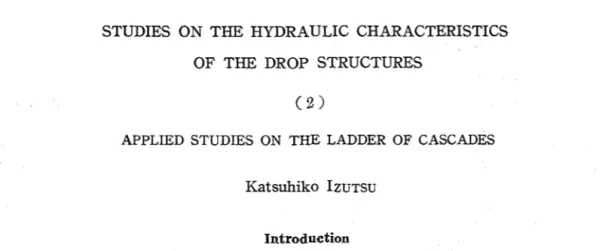
Fig. 2 Model ladder o f cascads
canal and the downstream canal (See Fig. 3). The three steps of the ladder of cascades
are the first, the second and the third stilling basin. One side wall of the canal and the ladder o,f' cascades was made of transparent plastic plate, for he could easily observe the flowing and dropping water, measure the water depth and take the photograph.
T h e other side wall and the canal bed were made of waterproof plywood. He used point- gauges for the depth measurment and pitot tubes for the velocity-head measurment.
"ctlo" f section
7
sectton C section 1)I
slope of 1 in 500 downstream canal slope of 1 k-500'-5
~ni
r---
{~+ZP
ir--L1
I--
1
5ectton A sectlon B section C section I) Fig 3 P ~ o f i l e and Plane of the model ladper of cascades Pzofile upstream canal Plane N -\ 2 2 -- I 0 0 1st stilllng basin L C 1 0
-I-?--
?- 7 5--
transition m +24
-
x
1 0 0 2nd s t ~ l l i n g basln m I--
I 0 0 3rd stilling basin232 Tech Bull Fac Agr Kagawa Uni9.
The process of the hydraulic model experiments was a s follows;
1) To make the experimental model a fourth part of the prototype.
2) To investigate a state of dissipating the enargy on the model.
3 ) To select a method which would dissipate the energy for improvements on the ladder o f cascades.
4) To make hydraulic experiments for it.
These hydraulic model experiments followed the Froude' s similarity. The ratio of simil- a ~ i t y is shown in Table 1 . The discharge
Table 1 Ratio of similarity on the hydraulic on the hydraulic model experiments was 60 model experiments l/sec, 80 lisec, 100 1 /sec, and 120 l/sec. kind of similarity Ratio of similarity They corresponded to l.g2m8/sec, 2,56mS/
length ~ a t i o 4 sec, 3.20ms/sec, and 3.872m8/sec on the
velocity ratio
area ratio 16
discharge ratio 32
prototype respectively. 3.872m8/sec (I20 l / sec on the model) was the designed high- water discharge.
Thinking hydraulic jump the best method to dissipate energy of supercritical flow, he set up a weir a t each outlet section of the stilling basins (See Table 2 ) . It was not the reason why the weir at section A took place hydraulic jump but made the outlet depth higher. The outlet depth is the water depth at an outlet section.
Results and Discussion
The complete nappe is aerated at the back of i t and drops freely. The incomplete naPpe
is not aerated a t the back of it and drawn to the back wall by the low pressure. Ther- efore, the incomplete nappe had a merit which its drcp length was much shorter than that of the complete nappe. And its demerit was unstable. The shorter d ~ o p length became effective, if hydraulic jump was about to occure in the limited stilling basin (Fig.8,
Vol. 18, No. 2 (1967) 233
Fig.9, and Fig. 10).
But there was little difference of energy-loss between the ccmplete and the incomplete
nappe
(Fig.12 to Fig.19). The second and the thirdfiappe
had always b e complete,because they fell with aeration and became many masses and drops of water, and so the air freely passed through the
naPpe
back and forth,i . e .
the upper and lowern a p p e
surfaces were subject to full atomospheric pressure.He wrote it in the former paper that the outlet depth was 72.4 percent of the critical depth('). If the weir was set up at section A, the outlet depth became higher than the former depth without a weirc4). An outlet depth with an incmplete
nappe
was lower than one with a completenappe,
for an inccmpletenappe
was drawn to the b a c ~ wall b y the low pressure. Setting up the weir which was 4 cm high, as shown in Fig. 11, the outlet depth was nearly equal to the critical depth with the ccmpletenappe
and 90 percent of the critical depth with the incompletenappe.
The outlet depth was higher, and the outletFig. 5 1 s t incomplete nappe and 1st stilling basin on ladder o,f cascade.^ (100 Z/sec)
Tech Bull. Fac. Agr Kagawa Univ
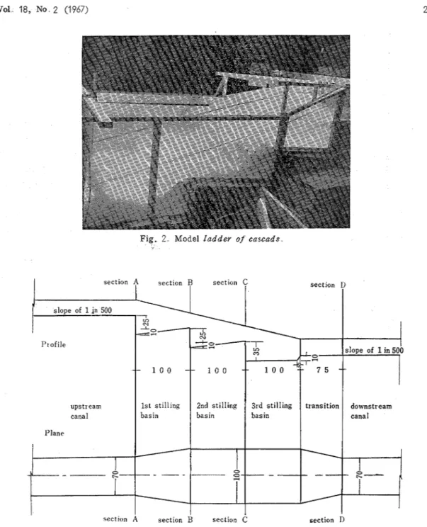
Eig 7 3 rd nappe and 3rd stilling basin on ladder of cascades ( 1 00 Z/sec)
Drop length, m
Fig 8 Relations between drop length of the first nappe and height of weir at
section A
Drop length, cm
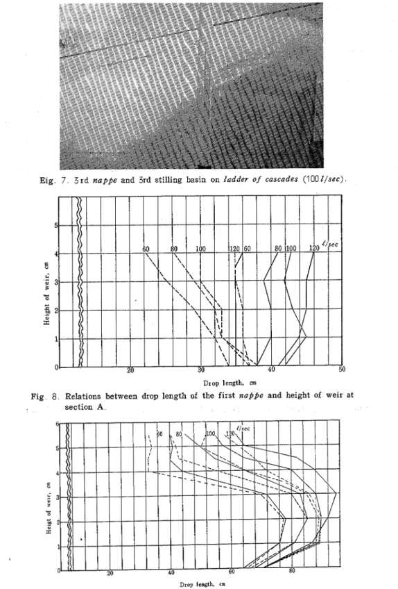
Fig. 9 Relations between drop length of the second nappe and height of weir
Vol .. 18,. No .. 2 (1 967)
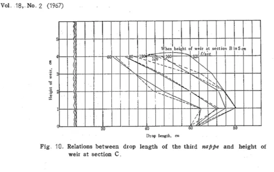
Drop length, cm
Fig 10 Relations between drop length of the thixd nappe and height of weir at section C
critical depth (120 C/sec)
n r
1
velocity was the slower. It is a merit for the nappe.,
The energy of the prototype was not only dissipated insufficiently but also acceleratedI
i on the ladder o f c ~ s c a d e s . Hydraulic jump was considered as the best method to dissipate
I
I excess energy of supercritical flow. If hydraulic jump occures in all the stilling basins,
the energy gradient must epual the slope of the ladder
o f
cascades. As the third stillingbasin had sufficient water depth to generate hydraulic jump, it had always occured in the third stilling basin. Then, he set up weirs at sections B and C and would get hydraulic
I jump in the first and the second stilling
basin. He made the hydraulic model experi-
1
ments on the various height of weirs(Tab1e
1 2 ) and four kinds of discharge which
changed f rom 60 l / s e c to 1 20 l/sec
.
1
I
.="
g Table 2 Height of weirs at outlet sections of
stilling basins on each experiment
-
Fig 11 ' 9 % Height of weir, on Numbex of experiment 1 st 2 nd 3 xd 4 th 5 th 6 th 7 t h 8 th Height of weir, Section A Section B cm Section CRelations between water depth and height of weir a t section A .
236 Tech. Bull. Fac. Agr
.
Kagawa UnivThe first experiment
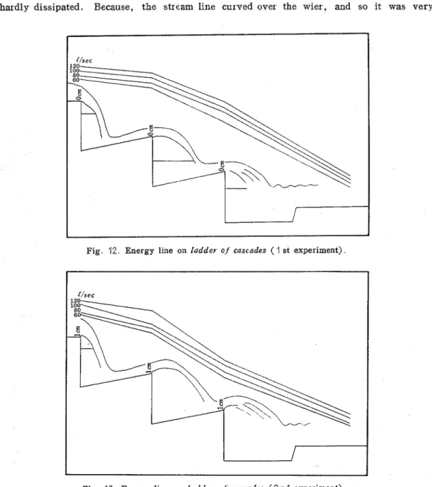
If the energy line runs parallel with the slope line of the ladder o f cascades, i t is an ideal ladder o f cascades as a dissipater. But, as the elevation head at section A turned into the velocity head at sections B and C, the energy was hardly dissipated i n the first and the second stilling basin. I n this case the energy line resulted in the worst condition.
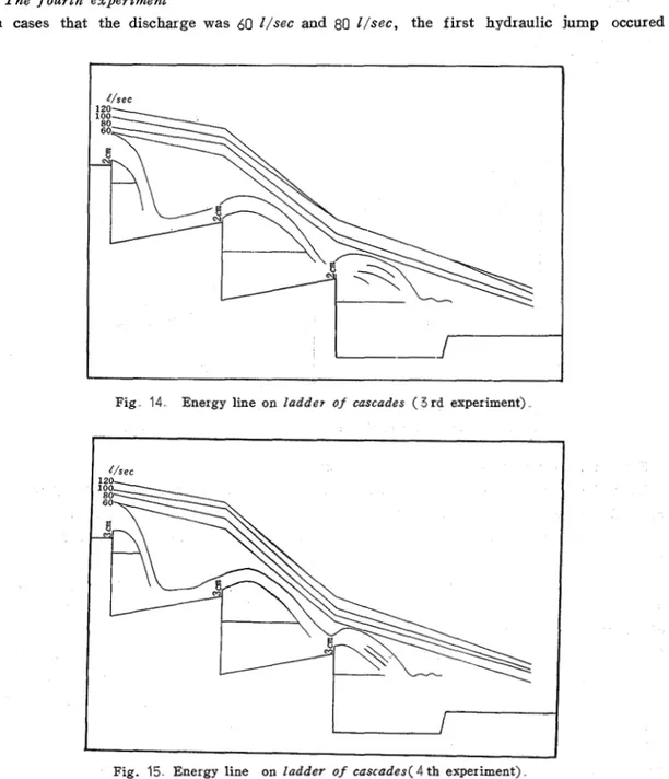
The second ex Per zment
The drop length of the second napfie mas longer than the first experiment. The drop
length of the third nappe was the lcngest of these experiments in case of every discharge. The total energy a t section C was much lower than the first experiment, though it was hardly dissipated. Because, the stream line curved over the wier
,
and so it was veryFig 12 Energy line on ladder of cascades ( I st experiment)
Vol 18, No. 2 (1967) 237 difficult that the pitot tube was exactly set toward the stream direction. After this exper- iment, it was observed that the total energy at section C tended to be lower than what it should be.
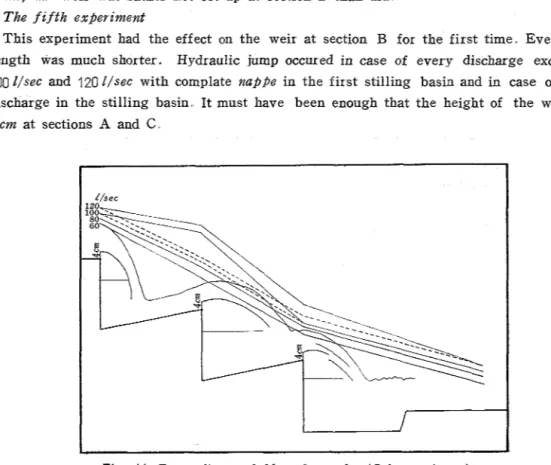
T h e t h i r d experiment
All drop lengths of the second nappe was the longest of these experinments in case of every discharge except that the discharge was 120 I/sec with the complete nappe. But there was a little difference between the first and the third experiment. The higher the weir was set, up the longer the length was. Consequently the shape of nappe was an arch.
T h e fourth experiment
In cases that the discharge was
60
Ilsec and 80 Z/sec, the first hydraulic jump occuredFig 14 Energy line on ladde7 of cascades ( 3 r d experiment)
238 Tech. Bull Fac Agr
.
Kagawa Univin the second stilling basin. If the drop length of the second naPpe had been shorter,
hydraulic jump would have occured in cases of other discharge, too. In case that the height of a weir changed from 0 cm to 3 cm, as shown in Fig. 12 to Fig. 15, there was scarcely distinction among their total eneIgy at section B. If the height of a weir was to
3 cm, the weir was rather not set up at section B than did.
The f z f t h experzment
This experiment had the effect on the weir at section B for the first time Every drop length was much shorter. Hydraulic jump occured in case of every discharge except for
100 Z/sec and 120 l / s e c with cornplate nappe in the first stilling basin and in case of every
discharge in the stilling basin It must have been enough that the height of the weir was
4 cm at sections A and C .
Fig 16 Fne~gy line on ladder o f cascades ( 5 th experiment). The szxth,the seventh and the ezghth experzment
When the height of the weir a t section B was 4.5 cm and discharge was 120 Z/sec with complete nappe, hydraulic jump had not occured yet in the first stilling basin. when the
height of the weir was 5.0 cm, hydraulic jump occured in all conditions. As it was
thought the energy a t section D to equal the energy at the outlet section of the third stilling basin, the energy gradient did almost equal the slope of the ladder o f cascades.
There are very little difference of experimental results between 5 0 cm and 5 . 5 cm i n height
of the weir at section B What there was a little difference between sections B and C must have due to the turblence of naPPe. As the height of the weir at section B had large influence on the second stilling basin and the third naPpe, what it was decided was one of
the most important problems on the ladder o f cascades. It was thought that the seventh
experiment type was suited as an improved type best of all
The energy lines on the ladder of cascades ar e shown in Fig. 12 to Fig 19 The horizontal scale is one-fortieth natural size of the model and the ve~tical scale is one-twentieth T h e
Vol. 18, No. 2 (1967) 239 energy lines with a complete nappe are shown by full lines. when the energy lines with a complete nappe do not equal the enerlines with an incomplete naPpe, they a r e shown by perforated lines. T h e illustrated profiles mean flowing and droping conditions in case of
120 l/sec on the l a d d e r o f casecade.
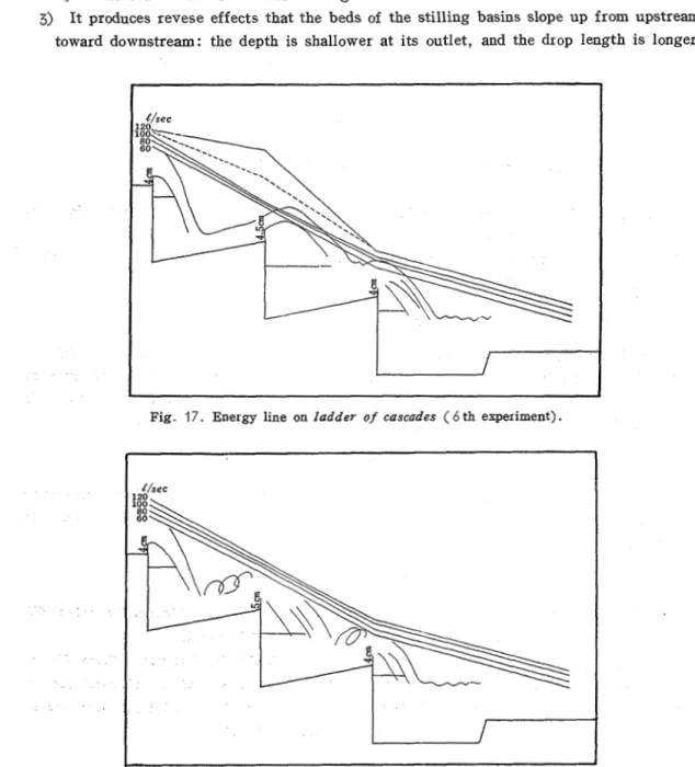
There are several problems on the design of the protype, as follows;
1) The length of the stilling basin must be insufficient for dissipating energy.
2) It is unreasonable that the three stilling basins are the same in length, for the hydraulic characteristics in each stilling basin are different.
3) I t produces revese effects that the beds of the stilling basins slope up from upstream toward downstream: the depth is shallower at its outlet, and the drop length is longer.
Fig. 17. Energy line on ladder of cascades ( 6 th experiment).
Tech Bull Fac Agr Kagawa Univ
Fig 19 Energy line on ladder of cascades ( 8 t h epxeriment)
Leveling the bed of the stilling basin and seting up a weir at its outlet, hudraulic jump must form easily in them.
4) Undular flow easily occures in the downstream canal, for the Froude' s number
canges from 0.8 to 1.0.
Summary
The auther made a field investigation into the drop structures in Karasu-gawa Valley, Nagano Prefecture, and he made hydraulic model experiment on the Gadder o f cascades
whose energy was not only dissipate insufficiently but also accelexated. Setting up a weir at each outlet, he took place hydraulic jump, and dissipated the energy enough.
Acknowledgements
The auther wishes to thank Prof. Toshisada NAITO, Assistant Prof. Mitsuo YAMAMOTO and Mr. Masao H o s o ~ o of Tokyo University of Education for their lead and advice to the work.
References
(1) I z u ~ s u Katsuhuko : Studies on hydraulic chara- (3) CHOW V T : Open-Channel Hydraulics, 423- cteristics of the drop structures, Tech. Bull 434(1959), McGraw -Hill
Fac Agr
,
Kagawa Univ 18-1, 70-76 (1966) (4) NAIIO Toshisada, YAMAMOTO Mitsuo, Hoso~o(2) TAKEDA Tsuneo : Renzoku-rakusako no Jisshi- Masao, Izusr u katsuhiko : Kaidan
-
I akusaka n o r e i ni tsuite, Suiro, Suiro-kenkyukai, 8, 19-30 nagare, Nagyadoboku -gakkai-taikai- kaenkaikaen-L P
E$!@Lg,
,@)ll?&gKaWb?LT L > Z5@4 D%%ID%fLkB?&'26 9 k%%, &$K~U¶E,&D$~Z~&%%%$$I s 7 k E @ @ % % % E 7 L 2 K L k
7kESX;@R@LB&SX;49D 4 f i D 1 k YkhAL < f i b \ , ?DBu¶%A?2%%iL J R t 2 B B D k & D 7k@BH%%%L k
T v - 4 K C ,Z J % k , &tiD@7k&DRhR53ifB
%tE-c$59, ~ ~ = 2 \ ~ v q - ~ . a % % & k ~ ~ % 7 k ~ l 6 % . & a j @ B k % k b & 6
R7k%@C P%&k LT@J!M%t7 iS 35, ~ L G ; ~ ~ ; ~ ~ ~ + ~ ~ D % & K R R ~ ~ ~ S ~ & $ ~ L \ ~ I . P T ~ ~ 's:
,
nappeD7RE % R S bK@cJTiZ9 T % L ~ @ % k k 9k
L7SaL, @ k l f & % % i E K L <&@D@7k&m~Z&K@t7k;5: ,&$Zi&?j&R, nappeD%@%V%~
<
7Ls: I), z % l vF-D.&$i*R%3%%RKJT&6 z 2 a S f i 9 k