Original
STUDY OF PERSONAL JOINT MOMENT IN HEAVY OBJECT LIFTING ACTION
Masahiko FUJIMURA and Rui YUGEGraduate School of Health Sciences, Hiroshima University
(Received: February 28, 2006)
Abstract
Since there were some unsolved matters of handling a heavy object in the past researches, we considered that it is especially significant to study the superiority between the personal knee joint extension condition (Stoop con-dition)and the personal knee joint flexion condition (Squat condition), and made some tests for ten (10) healthy persons. After attaching a marker to total twelve (12) parts: head term, 7th cervical vertebra, right shoulder top, right humeral lateral epicondyle, center of right wrist joint back, center of right side of body at the height level of xiphoid process, center of body at the level of right lumbar and sacral vertebrae junction (L5/S1), right trochanter, right femoral lateral epicondyle, right lateral malleolus, right 5th metatarsal condyle and top of right hallux, we took photographs of the motion of markers on the sagittal plane at 30 frames/sec. with the digital video camera and then, displayed them on the position coordinate. We calculated the moment from the equation of motion prepared every rigid body with the antebrachial region, upperbrachial region, head, upper trunk and lower trunk divided in the upper body model, and made a comparison between Stoop condition and Squat condition by use of the L5/S1 joint moment value for the personal posture when the joint moment value becomes the maximum one.
As a result, the personal load increased in the Squat condition. This cause was found that the distance be-tween the L5/S1 joint part, the heavy object and the center of gravity at the upper half of body becomes larger and that the weight of the upper half of body of tested person, which is added to the mass, increases the moment value. Next, we specified the time when the greatest moment is added to the L5/S1 joint. We expect that performing a job in recognition of this time can reduce an opportunity of being injured.
(JJOMT, 54: 129—136, 2006)
—Key words—
moment, carrying heavy objects, lumbago
1. Introduction
The method of expressing the personal body by use of the dynamic model and analyzing its characteristics is referred to the organicism. It is called industrial biomechanics in the industrial health region, and it is to carry out each evaluation and make improvements in work from the viewpoint of human engineering in order to prevent the physical trouble from being caused during work. In this study, we examined the relation between the way of lifting an object and the joint moment of 5th lumbar vertebra and 1st sacral vertebra (L5/S1) in accordance with the per-sonal knee joint extension condition (Stoop condition) and the perper-sonal knee joint flexion condition (Squat condi-tion).
The personal joint moment is the power level that something (object) supplies to a person, and the heavy ob-ject to be lifted and the tested person’s own weight are equivalent to the torque provided to his joint in this test. The personal joint moment is effective to verify the person’s activity. In this study, the video images were entered into the personal computer to display them on the position coordinate. And then, the personal joint moment value was calculated from the equation of motion.
The theory of equation of motion above is available by assuming that the personal body is a rigid link segment model and that the personal joint is a movable model at a pin joint. The mass of a segment shall be valid at one (1) point of gravity and also, the density of personal body portion shall be constant during a series of his action. There
are two (2) moment calculating methods: (a) from the lower limbs of foot to the upward joints in order (lower body model) and (b) from the upper limbs to the download joints in order (upper body model)1)
. In this study, we calcu-lated the moment from the equation of motion prepared every rigid body with the antebrachial region, upbrachial region, head, upper trunk and lower trunk divided in the upper body model, and also examined the per-sonal posture when the joint moment value becomes the maximum one.
2. Subjects and Methods
2-1. Subjects (Table 1)
The subjects were selected the ten (10) male healthy persons without the past and present clinical history of musculoskeletal system injury. In addition, we obtained their consent of test cooperation after fully pre-explaining the calculation methods and some danger that may occur to them as a result of the test.
2-2. Setting of Initial Angle of Knee Joint Flexion
We created the knee equipment to set the initial angle of knee joint flexion for heavy object lifting. This knee equipment was equipped with the dial lock for the knee joint so that the knee joint flexion could be limited. The cuff was attached to one (1) position of the upper part of thigh, two (2) positions of lower thigh and both sides of leg.
2-3. Setting for Heavy Object Lifting
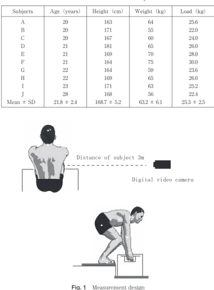
The weight of heavy object was set 40% of body weight of individual subjects (Table 1). The gravity of plastic case (39×29×20cm) was placed at the center, and also the upper surface of a heavy object was placed at the height of 3cm upward from the fibula lateral malleolus of subjects. The subjects stood toward the front of a heavy object,
Table 1 Characteristics of subjects
Load(kg) Weight(kg) Height(cm) Age(years) Subjects 25.6 64 163 20 A 22.0 55 171 20 B 24.0 60 167 20 C 26.0 65 181 21 D 28.0 70 169 21 E 30.0 75 164 21 F 23.6 59 164 22 G 26.0 65 169 22 H 25.2 63 171 23 I 22.4 56 168 28 J 25.3 ± 2.5 63.2 ± 6.1 168.7 ± 5.2 21.8 ± 2.4 Mean ± SD
and both legs were set to straddle to the breadth of his shoulders (Fig. 1). The test action was that a heavy object is lifted with the elbow joint extended while setting, as the start, the time when a heavy object leaves from the floor reaction device, and as the finish, the time when his trunk and lower limbs are completely extended in a posture, respectively. The speed of lifting a heavy object was set to any speed that the subjects can perform the test action smoothly. After performing two (2) trial practices, we calculated the angle of knee joint flexion at the start of lift-ing a heavy object in both the Stoop condition and the Squat condition.
2-4. Method of Taking Animated Cartoon
After attaching a marker to total twelve (12) parts: head term, 7th cervical vertebra, right shoulder top, right humeral lateral epicondyle, center of right wrist joint back, center of right side of body at the height level of xiphoid process, center of body at the level of right lumbar and sacral vertebrae junction (L5/S1), right trochanter, right femoral lateral epicondyle, right lateral malleolus, right 5th metatarsal head and top of right hallux, we took pho-tographs of the motion of markers on the sagittal plane at 30 frames/sec. with the digital video camera(DCR-TRV27 manufactured by Sony)and then, stored them into the personal computer (INSPIRON2500 by DELL), which is con-nected with the IEEE1394 cable, in the MPEG-4Codec operation system. The image analysis software “NIH Image1.63F” (National Institute of Health in United States) was used to specify the position of marker. The ob-tained data was compensated in depth before analyzing it.
2-5. Calculation of Joint Moment Value by Use of Image Data
Adobe Premiere 5.0J produced by Adobe Systems Incorporated read-in the video image, the edited animated cartoon was transformed into Apple Company’s Quick Time file and then, the picture analysis software NIH Image 1.63F was used to calculate the coordinate value of marker with 30Hz samplings.
We created the sheet that the formula of transforming the pixel value to the actual space coordinate value and the formula of getting the data graduation, gravity position and joint angle are entered on the basis of the coordi-nate value of marker by using the spreadsheet software Microsoft Excel 2000. Using the sheet calculated the grav-ity position and acceleration of each part of personal body and the angle of trunk anteflexion from the coordinates data, computing the personal joint moment. The approximate value of moments was calculated according to the es-timation method2)
of precedent research on the assumption that the action was carried out to right-and-left sym-metry with the floor reaction toward the perpendicular direction and the gravity of personal body on the action line. The weight and the gravity position of the personal body segments used to estimate the joint moment value were referred to the characteristic value of personal body of Le Veau3)
. 2-6. Estimation of Floor Reaction Value of Heavy Object
In order to estimate the weight loaded onto the metacarpus gripping a heavy object, we used the floor reaction device (G-620 manufactured by ANIMA) to measure the floor reaction value. We installed the detector on the floor and set a heavy object for test on it. For synchronization of data as the floor reaction value with the digital video camera, we took in data with 30Hz samplings and stored data into the personal computer (NB10AR manufactured by Fujitsu) to cope with the floor reaction device. In order to make same the time of starting measurement on the image and floor reaction device, we transmitted the 5V electronic signal from the floor reaction device to the per-sonal computer at the time of starting measurement, setting it as the trigger point.
2-7. Equation of Motion for Data Graduation and Calculation of Joint Moment Value
Data graduation is one of signal processing systems to process the digital data of time series, and the low-pass filter is often used for data graduation. As a filter for motion calculation data, the secondary Butterworth charac-teristics are often used to secure the flat characcharac-teristics in a passage region and its typical examples are the filters of Bryant J and Winter D4)~6)
. The filter of Winter is designed to cope with the 60Hz calculation data of TV camera, so that it has the small applicable range. On the contrary, since the filter of Bryant has an advantage to allow the cutoff frequency to be set arbitrarily, we used the Bryant filter in this study. With the calculation data X (t) at the time (t), the graduation data Xf (t) at the same time was calculated according to the following formula:
Formula of Bryant
Xf (t) = (X (t) + 2·X (t – 1) + X (t – 2)·W2
/B + C·Xf (t – 1) + D·Xf (t – 2) F = Fc / Fs
B = 1+√–2 ·W + W2
C = 2 · (1 – W2
)/B D = –(1 – √–2 ·W + W2
)/B
In the operation expression to calculate the joint moment, the digital type low-pass filter was used for removal of high-frequency noise. The use of a filter generally causes the delay of phase. The digital filter used in this opera-tion also causes the delay of phase (delay of time) due to the use of output values f (t-1) and f (t-2) prior to the out-put time (t). This delay of time was processed for data graduation by filtering on the reverse of the time base.
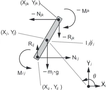
Next, the equation of motion to calculate the joint moment value was created according to the following for-mulas7)
:
mj · X¨j= Nij– Njk
mj ·Ÿj = Rij– Rjk – m · g
When the formula above is transformed: Njk = Nij– mj· X¨j
Rjk= Rij– mj(Ÿj+ g)
And, the equation of rotational motion:
Ij·θ¨j= Mij– Mjk+ (Yj– Yij) Nij– (Yj– Yjk) Njk– (Xj– Xij) Rij+ (Xj– Xik) Rjk
From the above formulas :
Mjk= Mij+ (Yj– Yij) Nij– (Yj– Yjk) Njk– (Xj– Xij) Rij+ (Xj– Xjk) Rjk– Ij·θ¨j
(References)
i: Next joint under target joint j: Target joint
k: Next joint above target joint
(Xj, Yj): X-Y coordinate values of gravity of joint “j”
(X¨j, Ÿj): X-Y coordinate values of gravity acceleration of joint “j”
(Xij, Yij): X-Y coordinate values of joint between joint “i” and joint “j”
(Xjk, Yjk): X-Y coordinate values of joint between joint “j” and joint “k”
(Nij, Rij): X-Y components of force supplied from joint “i” to joint “j”
(Njk, Rjk): X-Y components of force supplied from joint “j” to joint “k”
g: Gravitational acceleration
Ij: Moment of inertia around gravity of joint “j”
θ¨j: Rotational acceleration of joint “j”
Mij: Moment added through joint axis from joint “i” to joint “j”
Mjk: Moment added through joint axis from joint “j” to joint “k”
mj: Mass of joint “j”
In the equation of motion above, the lowest joint is the metacarpus gripping a heavy object.
The weight loaded to the metacarpus was calculated by use of the floor reaction value of a heavy object. Since the moment around a heavy object is zero (0), the force added to the above joint is found. Thus, a calculation was made from the hand joint, which is the lowest joint, toward the upper joints in order and estimated the L5/S1 joint moment value (Fig. 2).
2-8. Personal Posture Showing Max. L5/S1 Joint Moment Value
The angle of trunk anteflexion and the angle of knee joint flexion were calculated to examine the personal pos-ture showing the maximum L5/S1 joint moment value. Adobe Premiere 5.0J produced by Adobe Systems Incorpo-rated read-in the video image, the edited animated cartoon was transformed into Quick Time file and then, NIH Image 1.63F was used to calculate the angle. The angle of trunk anteflexion was specified the across angle between the centerline of personal body at the height of shoulder top and xiphoid process and the perpendicular line pass-ing the center of personal body at the height of xiphoid process. The angle of knee joint flexion was specified the across angle between the line connecting the trochanter to the femoral lateral epicondyle and the line connecting the fibula top to the fibula lateral malleolus.
3. Results
3-1. Joint Moment Value
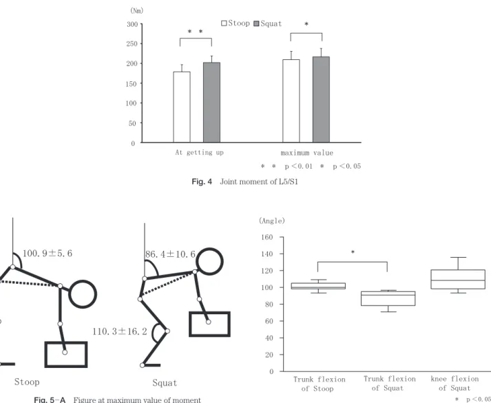
Fig. 3 shows the L5/S1 joint moment. The normalization of time was carried out because it is different in the work time from the start of lifting a heavy object (release from floor) to the termination. The L5/S1 moment be-came larger from the time when a heavy object released from the floor in the Squat condition, it bebe-came smaller after the maximum moment value, and finally, it became approx. 50% of the moment at the time when a heavy ob-ject released from the floor. We made a comparison of the L5/S1 joint moment value between a heavy obob-ject leasing from the floor and the maximum joint moment. The joint moment value at the time of a heavy object leasing from the floor was 178.7 ± 18.1Nm in the Stoop condition and 202.1 ± 16.8Nm in the Squat condition, re-spectively. In order to compare and examine the joint moment value in the Stoop condition and the Squat
condi-Fig. 2 Pattern diagrams for joint moment calculation
tion, the Paired t-test was conducted to approve the advantage p<0.01. The maximum moment value was 209.4 ± 21.1Nm in the Stoop condition and 216.7 ± 21.0Nm in the Squat condition, respectively. In order to compare and examine the joint moment value in the Stoop condition and the Squat condition, the Paired t-test was conducted to approve the advantage p<0.05 (Fig. 4).
3-2. Personal Posture Showing Max. L5/S1 Joint Moment Value
When the L5/S1 joint moment showed the maximum value, the angle of trunk anteflexion was 100.9 ± 5.6º in the Stoop condition and 86.4 ± 10.6º in the Squat condition, respectively. In order to compare and examine the joint moment value in the Stoop condition and the Squat condition, the Paired t-test was conducted to approve the ad-vantage p<0.05. The angle of knee joint flexion was 110.3 ± 16.2º at the peak level in the Squat condition (Figs. 5A and B).
4. Conclusion
The waist backbone disease in the industrial workplace has not been yet solved. A poor posture to work is con-sidered as a reason of this trouble. For solution of such a problem, it is necessary to examine in detail the waist bur-den that may cause a lumbago risk. In order to accomplish the purpose, it can be said that the organism and mech-anism analysis is effective with the waist limited. The waist consists of five (5) lumbar vertebrae. Among them, the lumbago often occurs to a space between the 5th lumbar vertebra and the 1st sacrum vertebra8)
. This means that the L5/S1 intervertebral disk has the largest movable region among the vertebrae with the large modification of in-tervertebral disk and is positioned at the lower part of trunk to support the big weight of the upper half of the body.
Fig. 4 Joint moment of L5/S1
Fig. 5 ─ A Figure at maximum value of moment
Fig. 5 ─ B Trunk and knee joint flexion angle at maximum value of moment
In this study, we examined the L5/S1 joint moment value when a person lifts a heavy object from the viewpoint of the organism and mechanism analysis in both the Stoop condition and the Squat condition.
When the joint moment value at the time of a heavy object releasing from the floor and the joint moment value become the largest, the Squat condition showed the significant larger L5/S1 joint moment in both cases. This mat-ter identified that the Squat condition has the disadvantage of the organism and mechanism evaluation in compar-ison with the Stoop condition.
The moment value is affected by (1) distance between fulcrum and point of application, (2) mass of rigid body and (3) travel speed. As to the distance between fulcrum and point of application, the Squat condition makes the waist go back, so that the distance between L5/S1 joint part, a heavy object and gravity of the upper half of the body becomes larger. The perpendicular line drawn from the L5/S1 joint part passes near the heel in the Stoop condition, but it passes further backward in the Squat condition. As to the mass of rigid body, it is considered that the Squat condition allowed the person’s own weigh to be added to the mass to increase the moment value.
In the past study, Mr. E. Welbergen with others and Mr. K. Hargen with others pointed out the decrease of labor effectiveness in the Squat condition including the increase of oxygen consumption. That the joint moment value in the Squat condition was larger than that in the Stoop condition in the calculation of this study supports these reports9)~10)
.
Next, we examine the personal posture showing the maximum L5/S1 joint moment value. We specified the time and angle at which the largest moment is added to the L5/S1 joint in this experiment. We expect that the per-son who handle a heavy object can reduce an opportunity of being injured by performing a job in recognition of this time.
Since the moment value is affected by the distance between fulcrum and point of application, the mass of rigid body and travel (lifting) speed as above mentioned, it is possible to decrease the moment value in consideration of three (3) elements above. Even if the distance between fulcrum and point of application and the mass of rigid body are made constant, the person who handle a heavy object can take the travel speed into consideration. Especially, we suggest that the person should take care to avoid the rapid lifting action at the time when the L5/S1 joint mo-ment value becomes larger as specified this time.
References
1) Lariviére C, Gagnon D, Loisel P : A biomechanical comparison of lifting techniques between subjects with and without chronic low back pain during freestyle lifting and lowering tasks. Clin Biomech 17 : 89—98, 2002.
2) Hattori T : Body up-down acceleration in kinematic gait analysis in comparison with the vertical ground reaction force. Bio-Med-ical Materials and Engineering 8 : 145—154, 1998.
3) Le Veau : Biomechanics of human motion. p.297—307, W. B. Saunders, 1992.
4) Bryant JT, Wevers HW, Lowe PJ : Method of data smoothing for instantaneous center of rotation measurements. Med Biol Eng Comput 22 : 597—602, 1984.
5) Winter DA, Sidwall HG, Hobson DA : Measurement and reduction of noise in kinematics of locomotion. J Biomech 7 : 157—159, 1974.
6) Cappozzo A, Gazzani F : Comparative evaluation of techniques for the harmonic analysis of human motion data. J Biomech 16 : 767—776, 1983.
7) Zatsiorsky VM, Seluyanov VN : The mass and inertia characteristics of the main segments of the human body. Biomechanics VIII-B : 1152—1159, 1983.
8) Genaidy AM, Simmons RJ, Christensen DM : Can back supports relieve the load on the lumbar spine for employees engaged in in-dustrial operations? Ergonomics 38 : 996—1010, 1995.
9) Welbergen E, Kemper HC, Knibbe JJ, et al : Efficiency and effectiveness of stoop and squat lifting at different frequencies. Er-gonomics 34 : 613—624, 1991.
10) Hagen KB, Hallén J, Karin HR : Physiological and subjective responses to maximal repetitive lifting employing stoop and squat technique. European J Appl Physiol Occup Physiol 67 : 291—297, 1993.
(原稿受付 平成 18. 2. 28)
別刷請求先 〒 734─8551 広島市南区霞 1 ─ 2 ─ 3
広島大学大学院保健学研究科 藤村 昌彦
Reprint requests :
Masahiko FUJIMURA, PhD, RPT
Graduate School of Health Sciences, Hiroshima University, 1-2-3 Kasumi, Minamiku, Hiroshima 734-8551, Japan.