GETTING STARTED GUIDE
NI PXI-5660
This guide explains how to install, configure, test, and begin using an NI PXI-5660 radio frequency (RF) vector signal analyzer, and introduces programming methods and examples. Refer to the 1. Verifying System Requirements section for information about additional documents.
Contents
Conventions ... 1
1. Verifying System Requirements ... 2
2. Unpacking ... 2
3. Verifying Kit Contents... 3
Other Required Items... 3
4. Installing the Software ... 5
5. Installing the NI 5660 ... 6
Installing the NI 5600 RF Downconverter Module ... 6
Installing the NI 5620 IF Digitizer Module ... 7
Installing PXI Modules... 7
Uninstalling PXI Modules ... 8
6. Interconnecting the NI 5660 Modules ... 8
Cooling Considerations... 10
7. Configuring and Programming the NI 5660 ... 10
Rename Both Modules... 11
Acquiring Data Interactively ... 11
Configuring Hardware Programmatically ... 14
Introduction to the Spectral Measurements Toolkit ... 17
Appendix A: Hardware Front Panel Connectors and Indicators ... 17
NI 5600 RF Downconverter Module ... 18 NI 5620 IF Digitizer Module ... 20 Appendix B: Troubleshooting ... 21 Installation ... 21 Configuration ... 23 Measurements ... 24
Technical Support and Professional Services ... 24
Conventions
The following conventions are used in this manual:
» The » symbol leads you through nested menu items and dialog box options to a final action. The sequence File»Page Setup»Options directs you to pull down the File menu, select the
Page Setup item, and select Options from the last dialog box.
This icon denotes a tip, which alerts you to advisory information.
This icon denotes a caution, which advises you of precautions to take to avoid injury, data loss, or a system crash. When this symbol is marked on a product, refer to the Read Me First: Safety and Electromagnetic Compatibility for information about precautions to take.
When symbol is marked on a product, it denotes a warning advising you to take precautions to avoid electrical shock.
When symbol is marked on a product, it denotes a component that may be hot. Touching this component may result in bodily injury.
bold Bold text denotes items that you must select or click in the software, such as menu items and dialog box options. Bold text also denotes parameter names.
italic Italic text denotes variables, emphasis, a cross-reference, or an introduction to a key concept. Italic text also denotes text that is a placeholder for a word or value that you must supply. monospace Text in this font denotes text or characters that you should enter from the keyboard, sections
of code, programming examples, and syntax examples. This font is also used for the proper names of disk drives, paths, directories, programs, subprograms, subroutines, device names, functions, operations, variables, filenames, and extensions.
monospace Italic text in this font denotes text that is a placeholder for a word or value that you must
italic supply.
Platform Text in this font denotes a specific platform and indicates that the text following it applies only to that platform.
1. Verifying System Requirements
Your system must meet certain requirements to use NI RF vector signal analyzers. For more information about minimum system, recommended system, and supported application development environments (ADEs), refer to the NI RF Signal Analyzers Readme, which is available with the NI-RFSA software.
Note After you install NI-RFSA, you can access the NI RF Signal Analyzers Readme at Start»
All Programs»National Instruments»NI-RFSA»Documentation or online at ni.com/ downloads.
2. Unpacking
RF vector signal analyzer hardware modules ship in antistatic packages to prevent damage from electrostatic discharge (ESD). Because ESD can damage several components of the hardware modules, store all modules in the antistatic envelopes when not in use.
Caution Never touch exposed connector pins.
To avoid damage when handling the RF vector signal analyzer hardware modules, take the following precautions:
• Ground yourself using a grounding strap or by touching a grounded object.
• Touch the antistatic package to a metal part of your computer chassis before removing the hardware module from the package.
Remove each hardware module from the package and inspect it for loose components or any signs of damage. Notify NI if any hardware module appears damaged in any way. Do not install a damaged module into your system.
3. Verifying Kit Contents
You need the following items to set up and use the RF vector signal analyzer. Listboxes represent physical kit items.
❑
Driver software disc—Installs the NI-RFSA and ni5660 instrument driver software and electronic documentation, including the following documents:– NI RF Signal Analyzers Readme—This HTML document includes information about the minimal and recommended system requirements, new features, installed file locations, and uninstalling/modifying the NI-RFSA instrument driver software.
– NI PXI-5660 Help—Use this online help file, located at Start»All Programs»
National Instruments»NI-RFSA»Documentation, to learn how to operate NI 5660 RF
vector signal analyzers.
– NI High-Speed Digitizers Help—Use this online help document, located at Start»All
Programs»National Instruments»NI-SCOPE»Documentation, to learn more information
about the IF digitizer module included as part of your RF vector signal analyzer. – NI-Tuner Help—Use this online help document, located in the Program Files»National
Instruments»<LabVIEW>»Help directory, for full access to the functionality of the
instrument drivers for the RF downconverter and IF digitizer modules.
❑
NI Spectral Measurement Toolkit CD—Installs the Spectral Measurements Toolkit (SMT) software components, which includes SMT VIs and functions, examples, and documentation.❑
1/8 in. combination Phillips/flathead screwdriver❑
The following printed documentation:– NI 5660 Getting Started Guide (this document) – Specifications documents for your device
– Read Me First: Safety and Electromagnetic Compatibility – Maintain Forced-Air Cooling Note to Users
❑
Two hardware modules:– NI 5600 RF downconverter module – NI 5620 IF digitizer module
❑
Short cables for interconnecting modules– One short, semi-rigid SMA-to-SMA coaxial cable – One long, semi-rigid SMA-to-SMA coaxial cable – One semi-flexible SMA-to-SMA coaxial cable
❑
Plastic collars (cable wrenches) for gripping the coaxial cable hex connectorsOther Required Items
❑
One of the following configurations:– (PXI system) A PXI chassis, PXI embedded or MXI controller system that meets the system
requirements specified in this guide, and chassis documentation.
– (PXI Express system) A PXI Express chassis, PXI Express embedded or MXI Express controller, and chassis documentation.
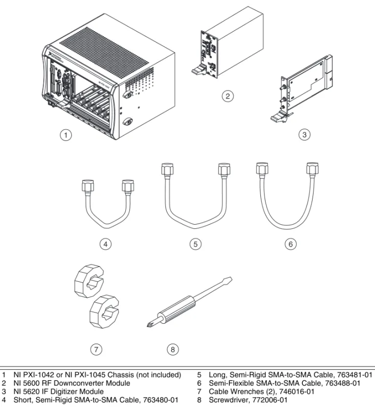
Figure 1. NI 5660 Kit Contents and Replacement Part Numbers
4. Installing the Software
Complete the following steps to install the components of the instrument driver software. You must install all of the included software before installing any RF vector signal analyzer hardware.
1. Install an application development environment (ADE) such as LabVIEW, LabWindows™/CVI™, or a third-party program according to its instructions. Any development environment you intend to use must be installed before you install the driver software and the Spectral Measurements Toolkit. 1 NI PXI-1042 or NI PXI-1045 Chassis (not included)
2 NI 5600 RF Downconverter Module 3 NI 5620 IF Digitizer Module
4 Short, Semi-Rigid SMA-to-SMA Cable, 763480-01
5 Long, Semi-Rigid SMA-to-SMA Cable, 763481-01 6 Semi-Flexible SMA-to-SMA Cable, 763488-01 7 Cable Wrenches (2), 746016-01 8 Screwdriver, 772006-01 4 5 6 1 NI PXI-104 2 8 7 2 NI 5600 POWER STATUS RF DOWNCON VERTER +20 dBm MAX +30 dBm MAXWIT H ATTN 3
2. Insert the NI-RFSA disc into the appropriate drive and follow the instructions in the installation window. You can choose to install NI-RFSA 2.1 (NI PXI-5661 and NI PXIe-5663) and/or
NI PXI-5660 Support.
(Windows Vista) Users may see access and security messages during installation. Accept the
prompts to complete the installation.
Note If the installation window. does not appear, navigate to the appropriate disk drive, and double-click setup.exe.
3. If you are using a system running the LabVIEW Real-Time Module, download NI-RFSA to the target using Measurement & Automation Explorer (MAX). Refer to the MAX Remote Systems Help by selecting Help»Help Topics»Remote Systems in MAX for more information about using MAX remote systems.
4. When installation completes, remove the driver software disc.
Note You must install the driver software before installing the Spectral Measurements Toolkit. 5. Insert the Spectral Measurements Toolkit CD.
6. Install the Spectral Measurements Toolkit for the ADE you intend to use. Follow instructions in the installation window.
7. When the installation completes, remove the Spectral Measurements Toolkit CD.
Note For full functionality, you must install the Spectral Measurements Toolkit packaged with the RF vector signal analyzer. The Spectral Measurements Toolkit extends the capability of the RF vector signal analyzer to include frequency- and modulation-domain measurements and analysis of analog-modulated IF signals.
8. Install any additional software that you intend to use with the RF vector signal analyzer after installing the driver software and the Spectral Measurements Toolkit.
Note If toolkits or other software that you intend to use with the RF device were installed before you installed the driver software, repeat or repair those installations after installing the driver software and the Spectral Measurements Toolkit.
Note The Spectral Measurements Toolkit includes examples for analog modulation and
demodulation. The Modulation Toolkit includes digital modulation and demodulation measurement functions. Both toolkits may be included in your RF vector signal analyzer shipping kit. You can also purchase and install the NI Modulation Toolkit at ni.com. Install NI PXI-5660 Support and the Spectral Measurements Toolkit before installing the Modulation Toolkit.
5. Installing the NI 5660
The NI 5660 modules are available in the PXI form factor. Installation of the NI 5660 RF vector signal analyzer hardware modules requires four vacant PXI (or hybrid) slots—three slots for the NI 5600 RF downconverter module and one slot for the NI 5620 IF digitizer module. The NI 5620 must be installed in the slot immediately to the right of the NI 5600 to allow for the use of the included coaxial cables.
Note You must install NI PXI-5660 Support before installing the hardware.
Installing the NI 5600 RF Downconverter Module
To install the NI 5600 module, complete steps 1 through 10 in the Installing PXI Modules section. Note The NI 5600 onboard frequency reference can drive the PXI backplane clock only if the
oven-controlled crystal oscillator (OCXO). You can also lock the NI 5600 to an external frequency reference clock signal and drive this reference to the backplane. To use an external frequency reference, you must connect this signal to the FREQ REF IN connector on the NI 5600 module front panel.
Installing the NI 5620 IF Digitizer Module
To install the NI 5620 module, complete steps 2 through 11 in the Installing PXI Modules section.
Installing PXI Modules
NI PXI modules are sensitive instruments that should be handled carefully. Do not expose the module to temperatures or humidity beyond the rated maximums.
Note For information about the rated maximums, refer to your device specifications document, located at Start»All Programs»National Instruments»NI-RFSA»Documentation»
Specifications.
Keep the module free of dust by cleaning only with compressed air. Do not clean the device with any solvents or liquids.
To prevent damage to the device caused by ESD or contamination, handle the device using the edges or the metal bracket. For more information about the radio-frequency interference characteristics of your hardware, refer to the Read Me First: Safety and Electromagnetic Compatibility document.
Caution You must power off and unplug the chassis before installing the device.
You can install PXI modules in any PXI slot marked with a peripheral slot compatibility glyph (a circle containing the slot number).
You also can install PXI modules in any PXI hybrid slot marked with a peripheral slot compatibility glyph (the letter “H” and a solid circle containing the slot number).
Install a PXI module by completing the following steps: 1. Power off and unplug your PXI chassis.
2. If the chassis has multiple fan speed settings, ensure that the fans are at the highest setting. Do not set the fan speed to low or turn the fan off.
3. Position the chassis so that you allow ample space between the chassis fan intake and exhaust vents. Blockage by walls or obstructions affects the air flow needed for cooling. Refer to the chassis documentation for more information about cooling.
4. Make sure the ejector handle is in the unlatched (downward) position.
5. Remove the rubber screw covers from the captive screws in the module front panel.
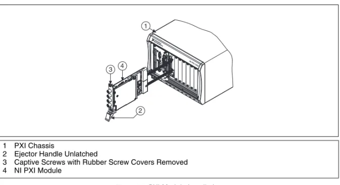
6. Holding the module by the ejector handle, slide it into an available PXI (or hybrid) slot, as shown in Figure 2. Ensure that the base card (the card on the left when looking at the front of the module) engages with card guides in the chassis.
7. Slide the module completely into the chassis and latch by pulling up on the ejector handle. 8. Tighten the screws in the module front panel. Performance may suffer if the screws are not
tightened properly.
9. Verify that the PXI chassis fans are operable and free of dust and other contaminants that may restrict airflow.
3
10. Install all chassis covers and filler panels after installing the RF vector signal analyzer hardware modules. Missing filler panels disrupt necessary air circulation in the chassis.
Note NI recommends installing slot blockers in adjacent vacant PXI slots to maximize cooling air flow to the RF vector signal analyzer hardware modules. The PXI Chassis Slot Blocker Kit (part number 778678-01) is available for purchase at ni.com.
11. Plug in and power on the PXI chassis.
Figure 2 shows the correct installation of a PXI module into a compatible chassis slot.
Figure 2. PXI Module Installation
Uninstalling PXI Modules
Power off the chassis prior to removing PXI modules. When removing PXI modules from the chassis, ensure that you are grounded with a grounding strap or are touching a grounded metal surface. To avoid ESD, do not touch the exposed connector pins or any exposed circuitry on the device. When not in use, PXI devices should be stored in the original antistatic envelope to avoid damage.
Hot Surface During operation, the metal surfaces of PXI devices may become hot. Be careful when removing the device from the chassis or when moving it to a different peripheral slot. When removing the device, hold it by only the ejector handle and front panel.
6. Interconnecting the NI 5660 Modules
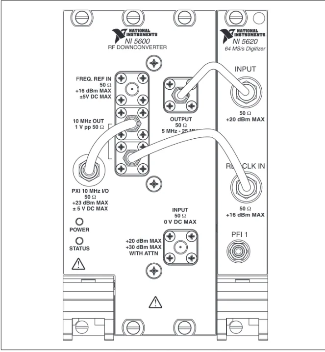
The NI 5600 and NI 5620 interconnect through the module front panels. Complete steps 1 through 6 to interconnect the RF vector signal analyzer hardware module front panel connectors, as shown in Figure 3.
1 PXI Chassis
2 Ejector Handle Unlatched
3 Captive Screws with Rubber Screw Covers Removed 4 NI PXI Module 3 2 4 NI P XI-1042 1
Figure 3. Interconnection of Devices with Included NI 5660 Cables
Note The published specifications document for your NI 5660 RF vector signal analyzer assumes use of the included cables. Substituting different cables may affect performance.
1. Using the short semi-rigid coaxial cable, connect the OUTPUT connector on the NI 5600 RF downconverter front panel to the INPUT connector on the NI 5620 IF digitizer front panel. Note The semi-rigid cables must be installed so the bends point upwards, as shown in Figure 3. 2. Using the long semi-rigid coaxial cable, connect the lower of the two 10 MHz OUT connectors on
the NI 5600 front panel to the REF CLK IN connector on the NI 5620 front panel.
Note The NI 5600 onboard frequency reference can drive the PXI backplane clock only if the RF downconverter module is installed in PXI Slot 2. When the NI 5600 is installed in PXI Slot 2, you can configure it to lock the PXI backplane clock to the highly accurate and stable NI 5600 onboard oven-controlled crystal oscillator (OCXO). You can also lock the NI 5600 to an external frequency
FREQ. REF IN 50 Ω +16 dBm MAX ±5V DC MAX 10 MHz OUT 1 V pp 50 Ω PXI 10 MHz I/O 50 Ω +23 dBm MAX ± 5 V DC MAX INPUT 50 Ω 0 V DC MAX 50 Ω +16 dBm MAX 50 Ω +20 dBm MAX OUTPUT 50 Ω 5 MHz - 25 MHz INPUT REF CLK IN PFI 1 NI 5600 NI 5620 64 MS/s Digitizer POWER STATUS RF DOWNCONVERTER +20 dBm MAX +30 dBm MAX WITH ATTN
reference clock signal and drive this reference to the backplane. To use an external frequency reference, you must connect this signal to the FREQ REF IN connector on the NI 5600 module front panel.
3. (Optional) Using the semi-flexible coaxial cable, connect the bidirectional PXI 10 MHz I/O connector on the NI 5600 front panel to the upper 10 MHz OUT connector on the NI 5600 front panel.
Caution Incorrect torque at SMA connections can degrade signal fidelity, phase-locked loop (PLL) performance, and insertion loss. Use an SMA torque wrench to ensure all SMA connections are properly torqued to 1 N · m.
4. Carefully tighten all SMA connectors to 1 N · m using an SMA torque wrench (not included), as shown in Figure 3. Tighten only until the wrench clicks.
5. Plug in and power on your PXI chassis and controller system.
6. Verify that the POWER LED on the NI 5600 RF downconverter module is illuminated. If the LED is not illuminated, refer to Appendix B: Troubleshooting.
You have completed installation of your NI 5660 RF vector signal analyzer.
Cooling Considerations
When installing a PXI module, follow the guidelines in the Maintain Forced-Air Cooling Note to Users document included in the kit to ensure that the device is cooled effectively.
Caution Inadequate air circulation could cause the temperature inside the chassis to rise above the optimal operating temperature for the RF vector signal analyzer hardware modules, potentially causing thermal shutdown, shorter life spans, or improper performance.
7. Configuring and Programming the NI 5660
Use Measurement & Automation Explorer (MAX) to configure your National Instruments hardware. MAX informs other programs about which devices reside in the system and how they are configured. MAX is automatically installed with the driver software.
To use MAX to configure, self-test, and functionally test the NI 5660 RF vector signal analyzer hardware modules, complete the following steps:
1. Launch MAX by navigating to Start»All Programs»National Instruments»Measurement &
Automation or by clicking the MAX desktop icon.
2. In the Configuration pane, double-click Devices and Interfaces to see the list of installed devices. 3. Expand the Traditional NI-DAQ (Legacy) Devices folder. You will see a list of installed devices
that includes the NI 5600 and NI 5620 modules (your default device names may vary). Note If you do not see the NI 5600 and NI 5620 modules listed, refer to Appendix B: Troubleshooting.
4. Note the device numbers assigned to your RF vector signal analyzer hardware modules by MAX. These numbers are used when programming the RF vector signal analyzer.
Complete steps 5 through 11 to self-test both modules. 5. Right-click NI PXI-5600 and select Properties.
6. The Configuring Device dialog box appears. Click Test Resources to self-test the NI 5600 RF downconverter hardware module. The MAX self-test performs a basic verification of hardware
7. The NI-DAQ Configuration Utility dialog box appears to confirm your self-test. Click OK to return to the Configuring Device dialog box.
Note If the NI 5600 RF downconverter module fails the self-test, refer to Appendix B: Troubleshooting.
8. In the NI 5600 Configuring Devices dialog box, click OK to return to MAX. 9. Right-click NI PXI-5620 and select Properties.
10. The Configuring Device dialog box appears. Click Test Resources to self-test the NI 5620 IF digitizer hardware module.
11. The NI-DAQ Configuration Utility dialog box appears. Click OK to return to the Configuring Device dialog box and continue with the NI 5620 test panel.
Note If the NI 5620 IF digitizer module fails the self-test, refer to Appendix B: Troubleshooting. You have completed setup, configuration, and testing of the NI 5660 RF vector signal analyzer.
Rename Both Modules
MAX allows you to rename both NI 5660 hardware modules. The MAX name is used in software to operate the NI 5660 hardware resources. You are not required to change the module names from the default names assigned by MAX, but doing so can make your program more readable. If you do not wish to rename the modules, proceed to the Acquiring Data Interactively section.
To rename both NI 5660 hardware modules, complete steps 1 through 7. 1. Right-click NI PXI-5600 and select Rename from the shortcut menu. 2. Enter the new name for the NI 5600 module.
Note The device name must consist only of alphanumeric and underscore characters. 3. Click OK.
4. Right-click NI PXI-5620 and select Rename from the shortcut menu. 5. Enter the new name for the NI 5620 module.
6. Click OK.
7. Verify that the new names for both modules are displayed before proceeding to the next section.
Acquiring Data Interactively
To interactively acquire data and perform measurements with the RF vector signal analyzer, use the included RFSA Demo Panel. The RFSA Demo Panel is accessible from within MAX at Tools»
Soft Front Panels»NI5660 - RFSA Demo Panel and from the Start menu at Start»All Programs» National Instruments»NI-RFSA»5660 Demo Panel.
Tip If an external signal source is not available, the signal from the 10 MHz OUT connector on the NI 5600 RF downconverter module front panel can be used as a source to verify proper RF vector signal analyzer installation and as a live signal for the RFSA Demo Panel. To use this signal, connect the 10 MHz OUT connector of the NI 5600 module to the INPUT connector on the NI 5600 RF downconverter module front panel.
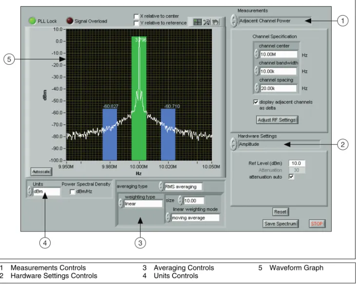
The RFSA Demo Panel (shown in Figure 4) provides a convenient software interface with which you can operate the RF vector signal analyzer hardware to perform common frequency-domain and I/Q measurements.
Figure 4. RFSA Demo Panel Performing ACP Measurement To use the RFSA Demo Panel, configure the following controls:
1. Verify that the device numbers in the RFSADeviceNumbers dialog box reflect those assigned to the RF vector signal analyzer hardware modules in MAX, and click OK.
2. Specify hardware parameters for your measurement, including the following parameters, in
Hardware Settings:
• RF Spectrum Settings • Amplitude
• Timing
• Advanced Spectral Parameters • Devices
1 Measurements Controls 2 Hardware Settings Controls
3 Averaging Controls 4 Units Controls 5 Waveform Graph 1 2 5 3 4
3. Specify the measurement you want to perform in Measurements. Choose one of the following options:
• Peak Search • Delta Peak • Power in Band
• Adjacent Channel Power (ACP) • Occupied Bandwidth
• IQ Data
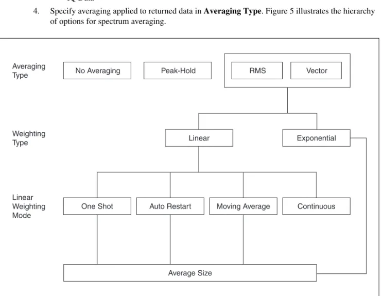
4. Specify averaging applied to returned data in Averaging Type. Figure 5 illustrates the hierarchy of options for spectrum averaging.
Figure 5. RFSA Demo Panel Spectrum Averaging Options
5. Specify units in which to return measurement results in Units. Several commonly used units are available. Exponential Average Size Peak-Hold No Averaging RMS Vector Averaging Type Linear Weighting Type Linear Weighting Mode Moving Average
Auto Restart Continuous
Configuring Hardware Programmatically
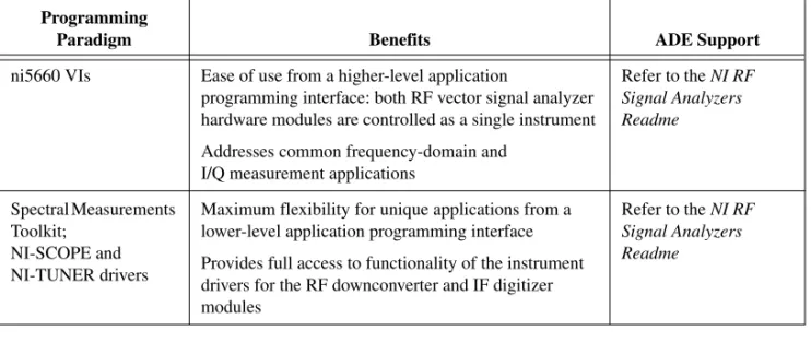
Two paradigms are available to programmatically configure the NI 5660 RF vector signal analyzer hardware for data acquisition, as shown in Table 1.
Note The NI Spectral Measurements Toolkit is used to perform measurements on the acquired data regardless of programming paradigm.
Programming the RF Vector Signal Analyzer in LabVIEW
To programmatically configure the RF vector signal analyzer hardware for data acquisition in LabVIEW, use the ni5660 VIs. These VIs control both the NI 5600 RF downconverter module and the NI 5620 IF digitizer module as a single instrument for frequency-domain and I/Q data acquisitions. The ni5660 VIs are located on the LabVIEW function palette at Instrument I/O»Instrument Drivers»
ni5660.
ni5660 LabVIEW VIs Programming Flow
The ni5660 VIs use two programming flows: a frequency-domain acquisition programming flow and an I/Q acquisition programming flow. Every application built using the ni5660 VIs must call the ni5660 Initialize VI and the ni5660 Close VI.
Frequency-Domain Measurements Programming Flow
Use the programming flow shown in Figure 6 to acquire data and perform frequency-domain measurements using the ni5660 VIs. Use the ni5660 Configure for Spectrum VI and the ni5660 Read Averaged Power Spectrum VI when Acquiring a Frequency Spectrum.
Table 1. Programmatic Configuration Paradigms for RF Vector Signal Analyzer Hardware
Programming
Paradigm Benefits ADE Support
ni5660 VIs Ease of use from a higher-level application
programming interface: both RF vector signal analyzer hardware modules are controlled as a single instrument Addresses common frequency-domain and
I/Q measurement applications
Refer to the NI RF Signal Analyzers Readme Spectral Measurements Toolkit; NI-SCOPE and NI-TUNER drivers
Maximum flexibility for unique applications from a lower-level application programming interface Provides full access to functionality of the instrument drivers for the RF downconverter and IF digitizer modules
Refer to the NI RF Signal Analyzers Readme
Figure 6. Acquiring a Frequency Spectrum
I/Q Acquisition Programming Flow
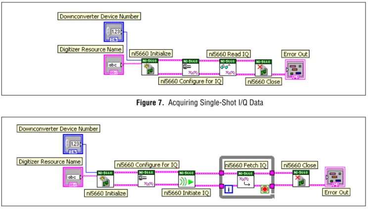
Use the programming flow shown in Figure 7 and Figure 8 to acquire I/Q data in single-shot or continuous modes, respectively. Use the ni5660 Configure for IQ Settings VI and the ni5660 Read IQ VI when Acquiring Single-Shot I/Q Data. Use the ni5660 Configure for IQ Settings VI, the ni5660 Initiate IQ VI, and the ni5660 Fetch IQ VI when Acquiring Continuous I/Q Data.
Figure 7. Acquiring Single-Shot I/Q Data
Figure 8. Acquiring Continuous I/Q Data
Example Applications for LabVIEW
Several example ni5660 VI applications are available for LabVIEW. These examples are intended to serve as interactive tools, programming models, and building blocks in your applications.
All installed ni5660 example files are located in the location specified in the NI RF Signal Analyzers Readme.
LabVIEW examples demonstrate integration of the NI RF vector signal analyzer with
NI RF signal generators and NI toolkit software, including the Modulation Toolkit. Refer to the NI Developer Zone on the Web at ni.com/examples for these examples and more information.
Programming the RF Vector Signal Analyzer in LabWindows/CVI and C
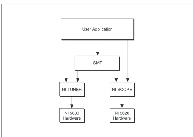
With LabWindows/CVI and C you can program the RF vector signal analyzer hardware modules individually, using function calls to the Spectral Measurements Toolkit and the individual drivers for the RF downconverter and IF digitizer modules. The following list describes the role of each program: • The Spectral Measurements Toolkit contains specialized functions for programming the RF vector
signal analyzer hardware for frequency-domain and I/Q measurements.
• The NI-SCOPE instrument driver controls the NI 5620 IF digitizer module and triggering of the RF vector signal analyzer.
• For more information about NI-SCOPE and triggering, refer to the NI High-Speed Digitizers Help, located at Start»All Programs» National Instruments»NI-SCOPE»Documentation.
• The NI-TUNER driver controls the NI 5600 RF downconverter module.
For more information about NI-TUNER, refer to the NI-TUNER Help, located at Start»
All Programs»National Instruments» NI-TUNER»Documentation.
The NI-SCOPE and NI-TUNER software components are depicted in Figure 9.
Figure 9. Software Flow Diagram for LabWindows/CVI and C
Note When programmatically operating the RF vector signal analyzer hardware, specify the NI 5620 IF digitizer module using the DAQ Resource Name with the following syntax:
DAQ::DeviceNumber
Specify the NI 5600 RF downconverter module using the MAX device number without modifiers. User Application SMT NI-TUNER NI 5600 Hardware NI-SCOPE NI 5620 Hardware
Introduction to the Spectral Measurements Toolkit
NI provides add-on software toolkits, such as the Spectral Measurements Toolkit (included) and the Modulation Toolkit, that extend the capability of the RF vector signal analyzer to include frequency- and modulation-domain measurements, and analysis of analog-modulated IF signals.
Note You must install the Spectral Measurements Toolkit CD packaged with your RF vector signal analyzer. The Spectral Measurements Toolkit is necessary for analysis of modulated signals using the RF vector signal analyzer.
Use the Spectral Measurements Toolkit (SMT) VIs and functions for frequency-domain analysis, measurement, and display of data acquired using the RF vector signal analyzer. The SMT can perform several operations, including the following:
• Zoom Fast Fourier Transform (FFT) processing and spectrum averaging
• Spectral measurements such as band power, adjacent channel power, and peak frequency and magnitude
• Spectrogram display and analysis
• RF vector signal analyzer hardware configuration for frequency-domain measurements For complete information about SMT VIs and functions, refer to the Spectral Measurements Toolkit documentation, accessible from Start»All Programs»National Instruments»Spectral
Measurements. For more information about the Modulation Toolkit, refer to ni.com/rf/ software.
SMT Example Applications for LabWindows/CVI and C
The Spectral Measurements Toolkit includes LabWindows/CVI and C examples for the RF vector signal analyzer hardware. You can access the Spectral Measurements Toolkit examples at Start»
All Programs»National Instruments»Spectral Measurements»CVI Support. The example files
are in the location specified in the NI RF Signal Analyzers Readme.
Appendix A: Hardware Front Panel Connectors and Indicators
The following sections describe the connectors and LED indicators on the front panels of all three RF vector signal analyzer hardware modules. All input and output terminals, except the PFI 1 connector on the NI 5622 IF digitizer front panel, are AC-coupled.
Note Refer to Figure 3, Interconnection of Devices with Included NI 5660 Cables, for illustrations of standard RF vector signal analyzer hardware module front panel interconnections.
NI 5600 RF Downconverter Module
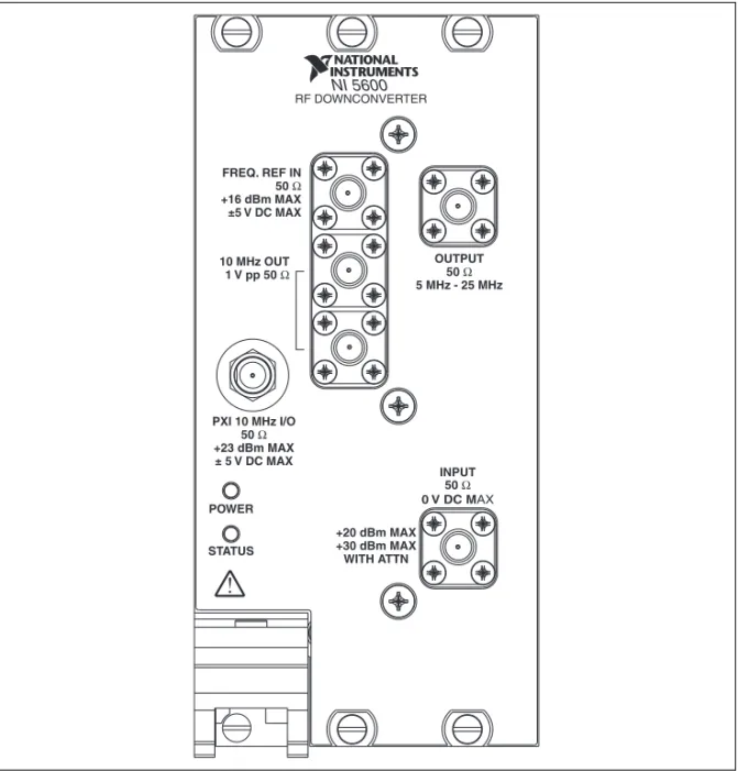
The NI 5600 RF downconverter module front panel contains six connectors and two LEDs, as shown in Figure 10.
Figure 10. NI 5600 RF Downconverter Module Front Panel
Note The PXI 10 MHz I/O connector can be used to route reference clock signals to the PXI backplane only when the NI 5600 RF downconverter module is installed in PXI Slot 2. This connector can export the PXI 10 MHz backplane clock from any NI 5600 PXI installation slot. For more information about exporting reference clock signals, refer to the NI PXI-5660 Help.
INPUT 50 Ω 0 V DC MAX OUTPUT 50 Ω 5 MHz - 25 MHz +20 dBm MAX +30 dBm MAX WITH ATTN PXI 10 MHz I/O 50 Ω +23 dBm MAX ± 5 V DC MAX 10 MHz OUT 1 V pp 50 Ω FREQ. REF IN 50 Ω +16 dBm MAX ±5 V DC MAX NI 5600 POWER STATUS RF DOWNCONVERTER
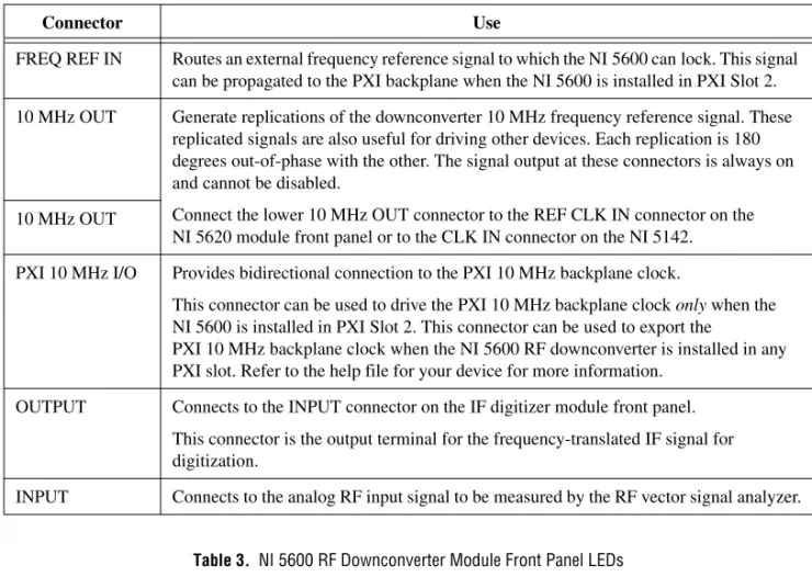
Table 2. NI 5600 RF Downconverter Module Front Panel Connectors
Connector Use
FREQ REF IN Routes an external frequency reference signal to which the NI 5600 can lock. This signal can be propagated to the PXI backplane when the NI 5600 is installed in PXI Slot 2. 10 MHz OUT Generate replications of the downconverter 10 MHz frequency reference signal. These
replicated signals are also useful for driving other devices. Each replication is 180 degrees out-of-phase with the other. The signal output at these connectors is always on and cannot be disabled.
Connect the lower 10 MHz OUT connector to the REF CLK IN connector on the NI 5620 module front panel or to the CLK IN connector on the NI 5142. 10 MHz OUT
PXI 10 MHz I/O Provides bidirectional connection to the PXI 10 MHz backplane clock.
This connector can be used to drive the PXI 10 MHz backplane clock only when the NI 5600 is installed in PXI Slot 2. This connector can be used to export the
PXI 10 MHz backplane clock when the NI 5600 RF downconverter is installed in any PXI slot. Refer to the help file for your device for more information.
OUTPUT Connects to the INPUT connector on the IF digitizer module front panel. This connector is the output terminal for the frequency-translated IF signal for digitization.
INPUT Connects to the analog RF input signal to be measured by the RF vector signal analyzer.
Table 3. NI 5600 RF Downconverter Module Front Panel LEDs
LED Indication
POWER Indicates the basic hardware power status of the NI 5600 RF downconverter module. This LED functions identically to the ACCESS LED on the digitizer module front panel. OFF—The module is not yet functional or has detected a problem with a PXI power rail. GREEN—The module is functional and receiving power.
STATUS Indicates the status of the NI 5600 RF downconverter module PLLs.
OFF—The module is in an uninitialized state, or the module PLLs are attempting to lock. GREEN—The module is in a ready state; applicable PLLs are locked.
NI 5620 IF Digitizer Module
The front panel of the NI 5620 IF digitizer module contains three connectors, as shown in Figure 11.
Figure 11. NI 5620 IF Digitizer Module Front Panel
50 Ω +20 dBm MAX 50 Ω +16 dBm MAX INPUT REF CLK IN PFI 1 NI 5620 64 MS/s Digitizer
Appendix B: Troubleshooting
This section discusses issues you may encounter during installation, configuration, and use of the RF vector signal analyzer hardware and software.
Installation
NI 5600 RF Downconverter Module Front Panel POWER LED is Off when PXI Chassis is On
If the POWER LED fails to light when the PXI chassis is powered on, a problem may exist with the PXI power rail, a hardware module, or the LED. Complete the following steps to troubleshoot this issue: 1. Power off your PXI chassis.
2. Remove any module front panel interconnections between the RF vector signal analyzer hardware modules.
3. Remove both RF vector signal analyzer hardware modules and inspect for damage. Do not reinstall a damaged device.
4. Reinstall both RF vector signal analyzer hardware modules in different PXI slots. Use the Installing PXI Modules procedure detailed in your device chapter.
5. Power on your PXI chassis.
6. If the POWER LED still fails to light, and failures continue, contact NI technical support or visit ni.com/support.
A Hardware Module Does Not Appear in MAX
Use the following procedure if any RF vector signal analyzer hardware module does not appear in MAX: 1. In the MAX Configuration pane, expand the Traditional NI-DAQ (Legacy) Devices folder. 2. Press <F5> to refresh the list of installed devices.
3. If the module is still not listed, power off the system, ensure that the RF vector signal analyzer hardware is correctly installed, and restart the system. If your hardware still does not appear, continue to step 4.
Table 4. NI 5620 IF Digitizer Module Front Panel Connectors
Connector Use
INPUT Connects to the OUTPUT connector on the NI 5600 RF downconverter module front panel.
This connector is the input terminal for a frequency-translated IF waveform from the NI 5600 RF downconverter for digitization and measurement.
REF CLK IN Connects to the lower 10 MHz OUT connector on the NI 5600 RF downconverter module front panel.
This connector is the input terminal for the NI 5600 internal reference clock signal. PFI 1 Receives a digital trigger from an external source. Refer to the NI High-Speed Digitizers
4. Open the Windows Control Panel and select System»Hardware»Device Manager. Complete the appropriate step for your setup:
• If you are using a PXI controller, verify that a National Instruments entry appears in the system device list. Reinstall the driver software and the RF vector signal analyzer hardware modules if error conditions are present in the list.
• If you are using a MXI-3 controller, right-click PCI-to-PCI Bridge and select Properties from the shortcut menu to verify that the bridge is enabled.
5. If the module still fails to appear in MAX, contact NI technical support or visit ni.com/ support.
The RF Downconverter Module Fails the Self-Test
The MAX self-test performs a brief test of device resources. If the NI 5600 does not pass the self-test, complete the following steps:
1. Restart your system.
2. Launch MAX and perform the self-test again.
3. Reinstall the NI 5600 module in a different slot as described in your device chapter. 4. Perform the self-test again.
5. If the NI 5600 RF downconverter module still fails the self-test, contact NI technical support or visit ni.com/support.
The IF Digitizer Module Fails the Self-Test
The MAX self-test performs a brief device resources test. If the IF digitizer module does not pass the self-test, complete the following steps:
1. Launch MAX by navigating to Start»All Programs»National Instruments»Measurement &
Automation or by clicking the MAX desktop icon.
2. In the Configuration pane, double-click Devices and Interfaces to see the list of installed devices. 3. In MAX, expand one of the following folders:
• For the NI 5620, expand the Traditional NI-DAQ (Legacy) Devices folder. You will see a list of installed devices that includes the NI 5600 RF downconverter and NI 5620 IF digitizer modules.
a. Right-click the IF digitizer module name and select Properties. b. The Configuring Device dialog appears. Click Test Resources.
c. In the Configuring Device dialog box, select Run Test Panels. The test panel performs a functional test of the IF digitizer module.
• For the NI 5142 and NI 5622, expand the NI-DAQmx Devices folder. You will see a list of installed devices that includes the NI 5600/5601 RF downconverter and NI 5142/5622 IF digitizer modules.
a. Right-click the IF digitizer module name and select Self-Test. 4. Click the Start button to run the test panel.
5. When the test panel has run successfully, click Close.
6. Click OK in the Configuring Devices dialog box to return to MAX.
7. If the test panel fails and continues to fail, contact NI technical support or visit ni.com/ support.
Configuration
RF Vector Signal Analyzer Does Not Initialize
Failure to initialize may indicate a problem with module interconnection or with MAX. If the RF vector signal analyzer fails to initialize, complete the following steps:
1. Reconnect the RF vector signal analyzer hardware module front panel cables securely as shown in your device chapter.
2. Power on your system and run the MAX configuration and self-test procedures in the 7. Configuring and Programming the NI 5660 section.
3. If failures continue, contact NI technical support or visit ni.com/support.
NI 5600 RF Downconverter STATUS LED Does Not Light
If the RF vector signal analyzer is programmed to lock to an external reference source or to the PXI backplane but the STATUS light does not indicate a phase locked status, check for the following errors: • Verify that a cable is connected from the external source or the PXI 10 MHZ I/O connector to the
FREQ REF IN connector.
• Ensure that the external source signal is large enough—typically greater than –10 dBm. • Ensure the external source signal falls within the specified frequency accuracy.
If you programmed the RF vector signal analyzer to use the NI 5600 RF downconverter module internal timebase, check for the following errors:
• If the RF vector signal analyzer measures the frequency incorrectly or detects no signal when one is supplied, one or more of the local oscillators is not phase-locked.
• If the RF vector signal analyzer measures the frequency correctly but the LED does not light, there could be a driver software error or the LED is damaged.
• If failures continue, contact NI technical support or visit ni.com/support.
The NI 5620/5142 IF Digitizer Module Does Not Phase-Lock to the RF Downconverter Module
If you programmed the IF digitizer module to phase-lock to the NI 5600 RF downconverter module internal reference through the front panel and you encounter failure, check for the following errors: 1. Verify that the cable is not faulty.
2. Ensure that there is a reference signal output from the NI 5600 10 MHZ OUT front panel connectors.
3. If there is no signal at these output terminals, contact NI technical support or visit ni.com/ support.
If you programmed the IF digitizer module to phase-lock to the PXI backplane driven by the NI 5600 RF downconverter module internal reference and you encounter failure, check for the following errors: • Ensure that the NI 5600 is in Slot 2 of the PXI chassis, immediately adjoining the PXI controller
slot.
• Verify that the PXI 10 MHZ I/O connector is securely wired to one of the 10 MHz OUT connectors using the included cable, as shown in your device chapter.
• Verify that the drive backplane clock parameter of the ni5660 Configure Reference Clock VI is set to TRUE.
Measurements
For more information about making measurements with the RF vector signal analyzer, refer to the NI PXI-5660 Help.
RF Vector Signal Analyzer Amplitude Reading Does Not Match Source
If the RF vector signal analyzer reports an incorrect amplitude reading, check for the following possible errors:
1. Check that the discrepancy between the RF vector signal analyzer and the source is within the error limits of the devices, as follows:
a. Verify the absolute amplitude accuracy of the RF vector signal analyzer. b. Verify the output level accuracy of the source.
2. Check for loss in the cables, which can be substantial. For example, RG58 coaxial cable loses about 2.1 dB of signal amplitude per foot at 2 GHz. Unless you are using high-quality cables, expect losses when working with high-frequency signals.
3. Ensure that you are using the amplitude calibration functions in the NI Spectral Measurements Toolkit. Failure to apply calibration functions can result in large amplitude errors.
4. If errors continue, contact NI technical support or visit ni.com/support.
Technical Support and Professional Services
Visit the following sections of the award-winning National Instruments Web site at ni.com for technical support and professional services:
• Support—Technical support at ni.com/support includes the following resources:
– Self-Help Technical Resources—For answers and solutions, visit ni.com/support for software drivers and updates, a searchable KnowledgeBase, product manuals, step-by-step troubleshooting wizards, thousands of example programs, tutorials, application notes, instrument drivers, and so on. Registered users also receive access to the NI Discussion Forums at ni.com/forums. NI Applications Engineers make sure every question submitted online receives an answer.
– Standard Service Program Membership—This program entitles members to direct access
to NI Applications Engineers via phone and email for one-to-one technical support as well as exclusive access to on demand training modules via the Services Resource Center. NI offers complementary membership for a full year after purchase, after which you may renew to continue your benefits.
For information about other technical support options in your area, visit ni.com/services, or contact your local office at ni.com/contact.
• Training and Certification—Visit ni.com/training for self-paced training, eLearning virtual classrooms, interactive CDs, and Certification program information. You also can register for instructor-led, hands-on courses at locations around the world.
• System Integration—If you have time constraints, limited in-house technical resources, or other
project challenges, National Instruments Alliance Partner members can help. To learn more, call your local NI office or visit ni.com/alliance.
• Declaration of Conformity (DoC)—A DoC is our claim of compliance with the Council of the
European Communities using the manufacturer’s declaration of conformity. This system affords the user protection for electromagnetic compatibility (EMC) and product safety. You can obtain the DoC for your product by visiting ni.com/certification.
CVI, National Instruments, NI, ni.com, and LabVIEW are trademarks of National Instruments Corporation. Refer to the Terms of Use section on ni.com/legal for more information about National Instruments trademarks. The mark LabWindows is used under a license from Microsoft Corporation. Windows is a registered trademark of Microsoft Corporation in the United States and other countries. Other product and company
• Calibration Certificate—If your product supports calibration, you can obtain the calibration
certificate for your product at ni.com/calibration.
If you searched ni.com and could not find the answers you need, contact your local office or NI corporate headquarters. Phone numbers for our worldwide offices are listed at the front of this manual. You also can visit the Worldwide Offices section of ni.com/niglobal to access the branch office Web sites, which provide up-to-date contact information, support phone numbers, email addresses, and current events.
スタートアップガイド
NI PXI-5660
このマニュアルでは、NI PXI-5660
無線周波数(RF
)ベクトル信号アナライザの取り付け、 構成、テスト、および使用開始の方法を説明するとともに、RF
ベクトル信号アナライザの プログラミング方法やプログラムサンプルを紹介します。その他のドキュメントについての 詳細は、「1.
システム要件を確認する」セクションを参照してください。目次
表記規則...1
1.
システム要件を確認する...2
2.
デバイスをパッケージから取り出す...2
3.
キットの内容を確認する...3
その他必要となるもの...4
4.
ソフトウェアをインストールする...6
5. NI 5660
を取り付ける...7
NI 5600 RF
ダウンコンバータモジュールを取り付ける...7
NI 5620 IF
デジタイザモジュールを取り付ける...7
PXI
モジュールを取り付ける...7
PXI
モジュールを取り外す...9
6. NI 5660
モジュールを相互接続する...10
冷却について...11
7. NI 5660
を構成およびプログラミングする...12
両方のモジュール名を変更する...13
対話式にデータを集録する...13
ハードウェアをプログラム的に構成する...16
スペクトル計測ツールキットの概要...19
付録A:
ハードウェアフロントパネルのコネクタおよびインジケータ...20
NI 5600 RF
ダウンコンバータモジュール...20
NI 5620 IF
デジタイザモジュール...23
付録B:
トラブルシューティング...24
取り付け...24
構成...26
測定...27
技術サポートおよびプロフェッショナルサービス...28
表記規則
このドキュメントでは以下の表記規則を使用します。 → 矢印(→)は、ネスト化されたメニュー項目やダイアログボックスのオプションを たどっていくと目的の操作項目を選択できることを示します。ファイル→ページ設 定→オプションと表記されている場合は、まずファイルメニューをプルダウンし、 次にページ設定項目を選択し、最後にダイアログボックスでオプションを選択しま す。 このアイコンは、ユーザへのアドバイスを示します。このアイコンは、注意すべき重要な情報を示します。 このアイコンは、人体への損傷やデータ損失、システムクラッシュなどを回避す るために必要な注意事項を示します。製品にこの記号が付いている場合は、『はじ めにお読みください
:
安全対策と電磁両立性について』を参照して必要な安全対策 を講じてください。 この記号は、電気ショックを防止するための事前対策についての警告を示します。 この記号は、熱を帯びる可能性があるコンポーネントを示します。このコンポーネ ントに接触すると、負傷する可能性があります。 太字 太字のテキストは、メニュー項目やダイアログボックスオプションなど、ソフト ウェアでユーザが選択またはクリックする必要がある項目を示します。また、パラ メータ名も示します。 monospace このフォントのテキストは、キーボードから入力する必要があるテキストや文字、 コードの一部、プログラムサンプル、構文例を表します。また、ディスクドライブ 名、パス名、ディレクトリ名、プログラム名、サブプログラム名、サブルーチン 名、デバイス名、演算名、変数名、ファイル名と拡張子にも使用します。 monospace ユーザが入力する必要がある語または値のプレースホルダを示します。 斜体 プラット 特定のプラットフォームを表し、そのすぐ後の記述はそのプラットフォームのみに フォーム 適用されることを示します。1.
システム要件を確認する
NI RF
ベクトル信号アナライザを使用するには、特定の要件を満たすシステムが必要です。 詳細な最低要件、推奨要件、サポートされるアプリケーション開発環境(ADE
)について は、NI-RFSA
ソフトウェアに含まれる『NI RF
信号アナライザReadme
』を参照してくだ さい。 メモNI-RFSA
をインストール済みのコンピュータでは、スタート→すべてのプログラム→National Instruments
→NI-RFSA
→ドキュメントを選択するか、ni.com/support/ja/downloadよりオンラインで『
NI RF
信号アナライザReadme
』を閲覧できます。2.
デバイスをパッケージから取り出す
RF
信号アナライザのハードウェアモジュールは、静電気放電(ESD
)による破損を防ぐた めに静電気防止用パッケージで包装し出荷されます。ESD
はハードウェアモジュールのコ ンポーネント破損の原因となる可能性があるため、すべてのモジュールは、使用していない ときは静電気防止用袋に入れて保管してください。 注意 露出しているコネクタピンには絶対に触れないでください。RF
ベクトル信号アナライザのハードウェアモジュールの取り扱い中に破損しないよう、 以下の予防措置を実行してください。•
接地ストラップを使用したり、接地されている物体に触れて、身体を接地する。•
静電気防止用パッケージをシャーシの金属部分に接触させてから、ハードウェアモ ジュールを取り出す。 各ハードウェアモジュールをパッケージから取り出し、部品がゆるんでいないかどうか、 また、破損箇所がないかどうか調べます。いずれかのハードウェアモジュールが破損してい る場合は、ナショナルインスツルメンツまでご連絡ください。破損しているモジュールはシ ステムに取り付けないでください。3.
キットの内容を確認する
RF
ベクトル信号アナライザの設定および使用には以下が必要です。見出しの四角マークは、 キットに含まれる実際の機器、部品類を表します。❑
ドライバソフトウェアのディスク —NI-RFSA
およびni5660
計測器ドライバソフトウェ ア、および以下のドキュメントを含む電子ドキュメントをインストールします。–
『NI RF
信号アナライザReadme
』— このHTML
ドキュメントには、システムの 最低要件および推奨要件、新しい機能、インストールされるファイルの保存場所、 およびNI-RFSA
計測器ドライバソフトウェアのアンインストールと変更の方法に ついての情報が記載されています。–
『NI PXI-5660 Help
』— このオンラインドキュメントはスタート→すべてのプログラム→
National Instruments
→NI-RFSA
→ドキュメントにあり、NI 5660 RF
ベ クトル信号アナライザの操作方法を習得する場合にお読みください。–
『NI
高速デジタイザヘルプ』— このオンラインヘルプドキュメントはスタート→すべてのプログラム→
National Instruments
→NI-SCOPE
→ドキュメントにあり、お使いの
RF
ベクトル信号アナライザの一部として含まれているIF
デジタイザモジュールの詳細について習得する場合にお読みください。
–
『NI-TUNER Help
』— このオンラインドキュメントはProgram Files¥NationalInstruments¥<LabVIEW >¥Helpディレクトリにあり、
RF
ダウンコンバータモジュールおよび
IF
デジタイザモジュール用計測器ドライバの機能の詳細について 調べる場合にお読みください。❑
NI
スペクトル計測ツールキットCD
— スペクトル計測ツールキット(SMT
)ソフトウェ アコンポーネントをインストールします。このコンポーネントには、SMT
のVI
および 関数、サンプル、ドキュメントが含まれます。❑
1/8 in.
プラス/
マイナスドライバー❑
以下の印刷版ドキュメント類:
–
NI PXI-5660
スタートアップガイド(このドキュメント)–
お使いのデバイスに付属する仕様書–
はじめにお読みください:
安全対策と電磁両立性について–
強制空冷の維持について❑
2
つのハードウェアモジュール–
NI 5600 RF
ダウンコンバータモジュール–
NI 5620 IF
デジタイザモジュール❑
モジュールを相互接続するための短いケーブル類–
セミリジッドSMA-SMA
同軸ケーブル(短)×1
–
セミリジッドSMA-SMA
同軸ケーブル(長)×1
–
セミフレキシブルSMA-SMA
同軸ケーブル×1
❑
同軸ケーブルの六角コネクタ固定用プラスチックカラー(ケーブルレンチ)その他必要となるもの
❑
以下のうちいずれか–
(PXIシステム)PXI
シャーシ、このガイドで指定されたシステム要件を満たすPXI
組込または
MXI
コントローラシステム、およびシャーシ関連ドキュメント。–
(PXI Expressシステム)PXI Express
シャーシ、PXI Express
組込またはMXI Express
コントローラ、およびシャーシ関連ドキュメント。❑
1 N
・m
標準SMA
トルクレンチ(部品番号187106-01
)、付属のSMA
ドライバービット図
1 NI 5660
キット内容および交換製品番号 1 NI PXI-1042またはPXI-1045シャーシ (別途ご用意ください) 2 NI 5600 RFダウンコンバータモジュール 3 NI 5620 IFデジタイザモジュール 4 セミリジッドSMA-SMAケーブル(短)(763480-01) 5 セミリジッドSMA-SMAケーブル(長)(763481-01) 6 セミフレキシブルSMA-SMAケーブル(763488-01) 7 ケーブルレンチ×2(746016-01) 8 ドライバー(772006-01) 4 5 6 1 NI PXI-1042 8 7 2 NI 5600 POWER STATUS RF DOWNCONV ERTER +20 dBm MAX +30 dBm MAX WITH ATTN 34.
ソフトウェアをインストールする
計測器ドライバソフトウェアのコンポーネントをインストールするには、以下の手順に従っ
てください。
RF
ベクトル信号アナライザのハードウェアを取り付ける前に、必ずすべての付属ソフトウェアをインストールしてください。
1. LabVIEW
、LabWindows
™/CVI
™などのアプリケーション開発環境(ADE
)、または他社製プログラムはそれぞれの説明書に従ってインストールしてください。また、使用す る開発環境のインストールは、ドライバソフトウェアおよびスペクトル計測ツールキッ トをインストールする前に行う必要があります。
2. NI-RFSA
ディスクをCD/DVD
ドライブに挿入し、インストール画面の指示に従います。
NI-RFSA 2.1
(NI PXI-5661
およびNI PXIe-5663
)およびNI PXI-5660
サポート、 またはいずれか一方を選択できます。 (Windows Vista)アクセス/
セキュリティメッセージが表示される場合があります。 画面の指示に従って、インストールを完了します。 メモ インストール画面が開かない場合は、該当するディスクドライブを開いて setup.exeをダブルクリックします。3. LabVIEW Real-Time
モジュールを実行するシステムを使用する場合は、Measurement & Automation Explorer
(MAX
)にてNI-RFSA
をターゲットにダウンロードします。