Memoirs of Nagano National College of Technology. No.35(2001) 11
Formability of YAG Laser Welded TRIP-aided Dual-phase Steel Sheets
Akihiko NAGASAKA Atsushi MIO Kazuhide WADA and Masakatsu SAITO
The effects of YAG laser welding conditions on mechanical properties and press fonnability (bendability, stretch-fonnability and deep drawability) of high strength TRIP-aided dual-phase (lDP) steel were investigated. Tensile tests and press forming tests have been conducted for laser butt welded joints obtained from the combination of the same steel. The tensile property and press formability were affected by the welding speed of 100 to 1100 nunlmin and the energy of S to 9 J/pulse. The excellent press fonnability was obtained by using the energy of 6 J/pulse and the welding speed of 300 nunlmin.
Itwas concluded that the excellent weldability of the lDP steel was ascribed to the weldjoints formation.
Key words: YAG laser welding, retained austenite, transformation-induced plasticity.
1. Introduction 2. Experimental Procedure
An
as-cold-rolled sheet steel with the chemical composition ofO.20C-1.5ISi - I.SIMn (mass%) 1.2 rom in thickness used in this study is shown in Table I. The
Table 1. Chemical composition of steels used (mass%).
~ C Si Mn P S Al
TOP 0.20 1.51 1.51 0.015 0.0011 0.040 MOP 0.14 0.21 1.74 0.013 0.0030 0.037
(a) TOP steel
(b) MOP steel 1200s
(in SALT BATH)
...
~
(in SALT BATH)
~
R
T L....J1..- -1...JI i
E-< 760 400 780
O.Q.
Time (s)
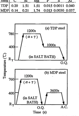
Fig. 1. Heat treatment diagram ofTDP and MDP steels. in which
"O.Q." and "AC."represent quenching in oil and air cooling, respectively.
• Retouch correction ofSISE'2001;July31 - August 2, 2001
•• Associate Professor, Department of Mechanical Engineering
• •• First Technical Section Received October 28.2001
Dual-phase steel associated with the transfonnation-induced plasticity (TRIP)[I] of the retained austenite
(YR), or lDP steel, possesses theexcellent press formability of high-strength sheet steels which were recently developed for shock safety and weight reduction of the automobile.[2-S] Hence, much research has been conducted to apply the steel to various automotive structural parts such as impact-prone parts and suspension parts.[6] The press fonnability of the lDP steel is expected to be controlled by the retained austenite parameters (volume fraction, carbon concentration and morphology), in the same ways as e1ongation[7 - 10], stretch-formability[II, 12] and stretch-flangeability.[13- IS] The tailored blank method has been applied for steel sheet welded structures.[I6] However, there have been few investigations dealing with the tailored blank from such a point of view.
In
this study, joint test specimens, all manufa.ctured
from the same materials, on which butt welding was
performed using a YAG laser, were fabricated.
Inorder to
clarify the laser process conditions required to form lDP
steel, tensile properties and press fonnability were
investigated.
12 Akihiko 01\C;.\SAKA, Atsushi 1\110. Kazuhide W,w.\, :Vlasakatsu '.\ITO
IDP steel was intercritically mmealed, and was austempered in salt baths, as shown in Fig, I(a). For comparison, 0.14C - 0.21Si - 1.74Mn (mass%) ferrite
(0./) -martensite
(o.m )dual-phase steel (MDP steel) subjected to heat treatment shown in Fig. I(b), was also prepared.
For butt welding, tile blank obtained after tile heat treatment was cut using a fine cutter, and YAG laser processing equipment (pulse oscillation, maximum average output of 350 W, maximum peak output of 4.5 kW) was used. The processing conditions were as follows.
Pulse energy
(E) and welding speed(F)were varied;
E=6mId 9
lIP,and
F=100 -II 00 mm/min. The pulse widtil was constmlt at 3.8 ms, mId the material was shielded by N
2gas,
Tensile tests were performed on
mlInstron tensile testing machine at a crosshead speed of I nun/min (strain rate 2.8X 10-
4Is), using J1S-13B-type tensile specimens.
TIle press formability was evaluated from tile minimum bending radius
(ROlin),tile maximum stretch-height
(Hmax )[12] and tile limiting drawing ratio
(WR).[5]The laser-irradiated side was made convex.
The volume fraction of tile retained austenite was quantified by X-ray diITractometry using Mo-Ko. radiation (five-peak metilod).[17] In addition, tile initial carbon concentration in the retained austenite (CyO, mass%) was estimated from tile lattice parameter (oyO, 11m) measured from tile (220)y diffraction
peakof Cr-Ko. radiation using tile following equation. [ 18]
C~o=(0~o-0.35467)/4.67X
10
J • • • • • • •(I)
3.2. Tensile properties after welding
Figure 3 shows tile relationship between tensile strengtil
(TS)and welding speed
(F),and tile relationship between total elongation
(TEl)and welding speed
(F).Total elongation of IDP steel was at a maximum for
F=200-400 mm/min at botil pulse energies, which was tile smne for conventional total elongation. MDP steel presented a similar tendency, altilough approximately 10%
total elongation was obtained.
lO.um
Table 2. Retained austenite characteristics and tensile properties.
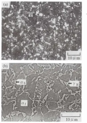
Fig. 2. Optical and scanning electron micrographs of TDP steel, in which white phases represent retained austenite and"ai',"Clj,"
and "YR" are fernte matrix, bainite island and retained austenite particle, respectively.
f volume fraction of second phase, I r
0:initial volume fraction of retained austenite, C r
0:initial carbon concentration in retained austenite, TS:
tensile strength, TEL: total elongation,
n:work hardening exponent and r: r-value.
n
0.26 0.72 0.08 0.80 Steel f I r
0TDP 10.35 0.09 MDPO.27 - 3. Results llnd Discus ion
3.1. Structure and tensile prop rties
Figure 2 shows optical and scmming electron micrographs of tile IDP steel, in which white phases in (a) represent tile retai.ned austenite. 'The optical micrograph was color etched using tile LePare metilod while tile scarming electron micrograph was etched in a 3% nital solution. The retained austenite mld bainite (
a b) phases astile hard second phase lie along tile ferrite grain boundary.
An
initial volume fraction
(fyO), and an initial carbonconcentration (CyO) of tile retained austenite in IDP steel were 9 vol% and 1.38 mass%, respectively (Table 2).
IDP teel presents a higher n-value compared to MDP st 1, however, tile r-value of TDP steel was low at less
\hun 10, similar to tilat of MDP steel.
FOImabiJity
of
YAG Laser Welded TRIP aided Dual phase teel heels13
0.5mm
L . - I20mm
Base metal'
8 0 0 . . - - - , 600
~400 200
0L...---l,---..."....-,:---J..---,-L::----7--7'
2.5 1 . 0 . . - - - , 0.9
f-! : E = 6 J / P TDP steel
B
~:~:.
., ./\~/~
_ . __0.6 -
-0- - -cf-. - t - - -
<)0.5
I I I Io 200 400 600 800 1000 F (mmfrnin)
Fig. 5. Example ofcross~eclionof YAG laser weld.(E=9lIP. F
=900mm/min)
Fig. 4. Appearance of some specimens in TOP steel.
Fig. 6. Variation in welding thickness ralio(1110)as a function of welding speed(F)in TOP steel.
(a)E=6lIP. F=300mm/min,(b)E=6lIP, F=500 mm/min.
Fig. 7. Variation in Vickers hardness(HV)at the cross section of dislance from center of weld zone(W)in TOP steel.
'0
9 0 0 . . - - - ,
(a)
TDP dDP (E=9J/P)
'C?800 ~~10--0,
~ MDP ~ -.. _ D
~ 700 . MDP TDP (6J/P)
/ (6J/P)
600
~::::::=::::::::=====::::::==============~(b) o-TDP
Fig. 3. Varia lions in (a) tensile strength (TS) and (b) tolal elongation(TEf)as a function of welding speed(F)in TOP and MOP steels.
Figure 4 shows an example of the appearance of the fractured tensile test specimen
(E=6 lIP).The specimen in (a), when F=300 mm/min, was fractured away from a weld joint., while the specimen in (b), when F= 500 mm/min, was fractured at a weld joint. Accordingly, obtaining total elongation equal to the co.nventional total elongation indicated that the joint was in good condition.
Figure 5 shows a sample of the cross section of a weld joint,
3%of which was etched by nital
(E=9lIP, F=900 mm/min). The white area in the middle of the image was completely transformed to am and the black area was a heat-affected zone
(HAZ).Penetration of a bead was completely achieved in the form of a V shape, resulting in a decrease in the thickne s of the bead
(I)compared to the thickness of the sheet
(to).The lower the welding speed, the greater the rectangular penetration and the larger the area transformed to am and
HAZ.Figure 6 shows the relationship between the thickness ratio
(1110)of the thickness of the completely penetrated bead
(I)to the thickness of the sheet
(to)and welding speed
(F).Figure 7 shows the distribution of Vickers hardness
HV (load 0.98 N)from the center of a weld joint. As a
standard to determine the appropriateness of the bead
shape,
t1to~0.7is proposed, indicating that when
1110<0.7,rupture occurs at a weld joint., and when
Illo~0.7,rupture
occurs in the base metal.[16] A substantial decrea e in total
elongation shown in Fig. 3(b) occurring when
E=6 lIPand F> 300 mm/min was attributed to incomplete joint
penetration. When
E=9
lIP,total elongation decreased
similarly, but since joint bead penetration was complete,
14
Akihiko NAGASAKA,Atsushi MIO, KazuhideWADA, MasakatsuSAITOthe rapid decrease in total elongation observed when E=6
JIPwas not observed. Meanwhile, in the range of low
F(F<200 mm1min) when E=6
JIP,bum through occurred in the base metal, and again tlto<0.7 and the minimum cross-sectional area decreased, resulting in the promotion of regional deformation (Fig. 6). A n-value of 0.2 or greater across a weld joint was maintained, indicating a high work hardening exponent (Table 2); however, it is difficult to say whether good elongation can be consistently obtained because constraint of the base metal in the welding direction is high. As the reason for this, we considered that since the hardness ratio of a weld joint transformed to
a",(HV600) to the base metal (HTt290) was approximately two (Fig. 7), the constraint in the direction of the sheet width was increased.
3.3. Formability after welding
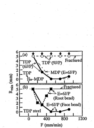
Figure 8 shows the relationship between the minimum bending radius
(Rmin)and welding speed
(F). InFigs. 8(a) and (b), the laser irradiated surfaces were made face bend and root bend, respectively. Figure 9 shows the relationship between the maximum stretch-height (HmaJ and welding speed
(F),and the relationship between the limiting drawing ratio
(WR)and welding speed
(F). InFig. 8(a), when E=6
JIPand F=3oo mm1min or greater,
Rminwas almost minimum and the bendability appeared to be good, while when E=9
JIP,R
minwas 5 rum or greater and the bendability was poor, i.e., fracture occurred.
InFig. 8(b), when E=6
JIPand F=300 mm1min, R
minwas minimuni This was due to a change in shape of the laser surface induced when E= 9
JIP,which acted as a notch and caused concentration of stress. Meanwhile, the stretch formability and deep drawability decreased compared to the conventional
Hmaxand
WR.As the reason for this, we considered that since the hardness ratio of a weld joint transformed to
a",to the base metal was approximately
·two, stretching deformation was constrained to the weld joint when the surface area was expanded due to stretch forming, and the drawing resistance of the shrinking flange
wasconstrained and increased by deep drawing.
Accordingly, the optimal laser welding condition for forming IDP steel was found to be around F= 300 mm1min atE=6
JIP.4. Conclusions
The effects of YAG laser welding conditions on mechanical properties and press formability of high strength lRIP-aided dual-phase (IDP) steel were
investigated. The principle conclusions are summarized as follows.
(1) The optimal laser welding conditions for forming IDP steel were found to be a pulse energy E=6
JIPand a welding speed F= 300 mm1min.
(2) The optimal condition was when bead penetration was completely achieved and the ratio of bead thickness
tto sheet thickness to was tl to!;;. 0.7.
6r----:--~---:::__-:--~--,
5 4 3 2
8 1
,§, 0
.~ 6:=='====================:=1
~ 5 4 3 2
o 1
1200
Fig. 8. Variation in minimum bending radius (Rmin) as a function' of welding speed (I') in TOP and MDP steels.
12~:---~
Ja)oTDP
1 8 -
l::!. .TDP (E=6J/P)
- _MD~_ .• _.
~ 4- - --
= 7-·--
- I ;rDPI(9J/~)
MpP (yJ/P)
o P:(:=:b )::!O=T=D:!::P=:!::=======:!::=~
MDP (E=6J/P)
~2.0-~p ~_.-z _.
91.81- TDP ,
(9J/P) . b TDP (6J/P)
I I I I I I
1.6~--:o~--L..---;:40~0:--'--:::::800!:-::--I--:l:-::!20·0 F (mm/min)
Fig. 9. Variations in (a) maximum stretch-height(Hm..)and (b) limiting drawing ratio(WR)as a function of welding speed (I').