Acquisition of designable space for planar steel frames
M. Yamanari
1& H. Tanaka
11
Graduate School of Science and Technology, Department of Architecture, Kumamoto University, Japan.
Abstract
This paper describes on a methodology for acquisition of designable space for planar steel frames. Here, the designable space is obtained out of the universe, which contains the all set applied for a structural design of a building. A designer takes some sets of solutions simultaneously using a new concept design system, although he or she gets only one set of solutions with conventional method. The new concept design system was developed taking account of knowledge system and data flow system.
For convenient structural design system for not-skilled engineers and students, a new concept is needed to be introduced to conventional structural design system. It is laborious for such beginners to be skilled up in structural design, because they spend match time to find the rational solution out of a lot of designable solutions.
The new concept structural design system is developed with Excel and DSP.
It is the reason why Excel is taken for the development that it is the most popular spread sheet type application and has programming language of VBA. DSP is the special computer language, which is developed by Nagasawa and possesses high potential for writing of design codes. This system has capability of getting designable solutions simultaneously. This is a proof of the new concept as acquisition of Designable Space. Demonstration was conducted how a designable space moves in the whole design space.
Keywords: Structural Design, Computer Assisted Design, Design Space
1 Introduction
This paper describes on both a concept of acquisition of designable space and a methodology for acquisition of pertinent solution for planer steel frames. A structural design system of arbitrary shape steel planar frame based on knowledge system was developed in this study. The system is different from other conventional structural design systems in the concept and the architecture of processing. Those conventional structural design systems often force the beginner in structural design the labor in finding the rational or best solution. So it is difficult that the systems make them skillful in short time, though the systems are used as effective tools for the structural design experts. The study aims at developing the system that advances structural design skills for structural design beginners. There are various knowledge based Expert systems for structural design [1], although they are not suitable for the beginners.
2 Designable space and pertinent solution
2.1 Acquisition of design solution
An action of structural design is selecting a unique rational or reasonable data set (it is called pertinent solution in this study) applied for structural design of a building from all designable data set (it is called design space in this study) . However there are a lot of designable data set in the design space. It is inefficient to calculate all sets at one time, because much time is necessary to achieve the job. Therefore, some design solutions (it is called designable space in this study) under constrained condition are acquired from design space and pertinent solution finally acquired by moving designable space in design space [2]. In the study, pertinent solution is distinguished from optimal solution. Pertinent solution is selected by designer’s decision, though optimal solution can be calculated automatically in such as the most or least problem.
Chosen frame
a
b
Design space
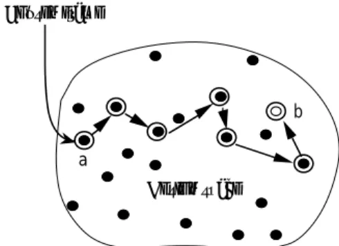
Figure 1: Pertinent solution search in a conventional structural design system.
2.2 Comparison of New concept with Conventional method
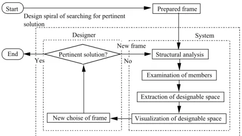
There is a model depicting pertinent solution search in a conventional structural design system as shown in Figure 1. In the pertinent solution search in a conventional structural design system, a designer takes the first prepared frame (a, in Figure 1) and examines the frame for structural design using the result given by the system. When designer is satisfied the frame, the design process is finished at this step. If not, designer has to select other frame out of design space and examines the frame. In this way, he or she implements pertinent solution search from doing a rundown.
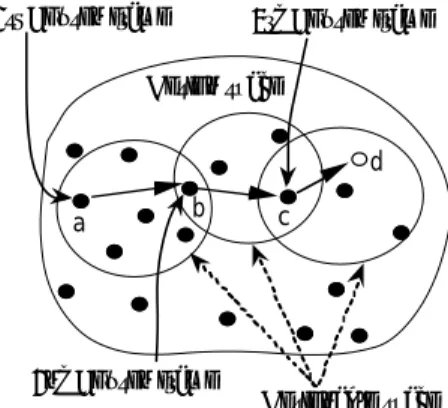
On the other hand, there is a model depicting pertinent solution search described 2.1 shown in Figure 2. In this process, a designer takes the first prepared frame (a, in Figure 2) as same as above and he or she acquires some designable frames (designable space) constituted by members that have close dimension of the member that constitutes assumed frame at a time. When the designer reasons that the point marked b is the best frame fulfilled design condition, the design process is finished at this step. If not, the designer decides point b as new assumed frame and implements acquisition of new designable space. In this bout, if the designer reasons that point c is the best frame fulfilled design condition, this design process is finished. But if not yet, the designer repeats additionally with the same methodology and acquires pertinent solution (d, in Figure2) for the last time.
1st Chosen frame
a b c
d Design space
Designable space 2nd Chosen frame
3rd Chosen frame
Figure 2: Pertinent solution search in the new structural design system.
3 New concept design system
3.1 Development of a new concept steel structural design system
A new concept structural design system, that is achieved design process concept
described in Chapter 2, for steel planar frames was developed in this study. The
system is applied to arbitrary shape steel planar frames. The system was
developed with Excel and DSP. Excel is the most popular spreadsheet type
system, which has programming language Visual Basic for Applications (VBA) and is able to handle figure or graphics on the sheet. It is convenient for dealing with arbitrary shape frame design. On the other hand, DSP is the special computer language. DSP is the special computer language, which is developed by Nagasawa and possesses high potential for scripting of design codes and also has function of generate-and-test method [3]. It is the reason why Excel is taken for the development that it is the most popular spreadsheet type application and has programming language of VBA.
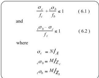
Structural member design in a steel frame is based on the specification for steel structure design in Japan [4]. The expression of equations and notations described in the specification generally has the form shown in Figure 3. However, if those in Figure 3 are coded in the conventional computer language such as Basic or Fortran, the description sequence of program code must be deferent from the sequence shown in Figure 3. So it is necessary a large amount of labor to develop whole system, when the system is programmed in Basic or Fortran.
!
c+
c!
bf
cf
b" 1
!
bt –
!
cf
t" 1 and
where
( 6.1 )
( 6.2 )
!
c= N A
!
bc
= M Z
c!
bt
= M Z Z
ttFigure 3: Expression of equations and notations in design specification.
On the other hand, DSP is spreadsheet type application and it has concept of data flow. So programmer doesn’t have to take care of sequence of program code.
Therefore, not only a usual computer programmer but also a designer, who is not familiar to program coding, can develop a system by oneself, and he or she can rapidly respond to change of design specification.
4 Outline of the system
4.1 Graphical user interface of arbitrary shape steel planar frame
It is necessary a graphical user interface (GUI) for a system user to design an
arbitrary shape steel planar frame for visualization. In the study, Excel is used for
GUI of the system. It is the reason why Excel is taken for the development that it is the most popular spreadsheet type application and has programming language of VBA. Also it can handle graphics on the sheet. It sets some buttons and menus to be able to implement selection and change for input and output by the mouse.
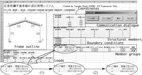
An outline of arbitrary shape frame is drawn at upper left on the sheet, information of structural members and load conditions appear also.
Demonstration of the methodology for acquisition of pertinent solution, which authors assert is shown in Figure 5 and Figure 6.
(1) (2)
1 2
3
4
5 [4]
[2] [3]
[1]
Communication dialogue
Structural members Boundary conditions
Member groups Loads
Frame outline
Coordinates
Figure 4: View of spreadsheet and process of change of members.
An example process of the methodology is described as below. One set of structural members such as beams and columns of which consist the frame is prepared for the first structural analysis and examination of all the members.
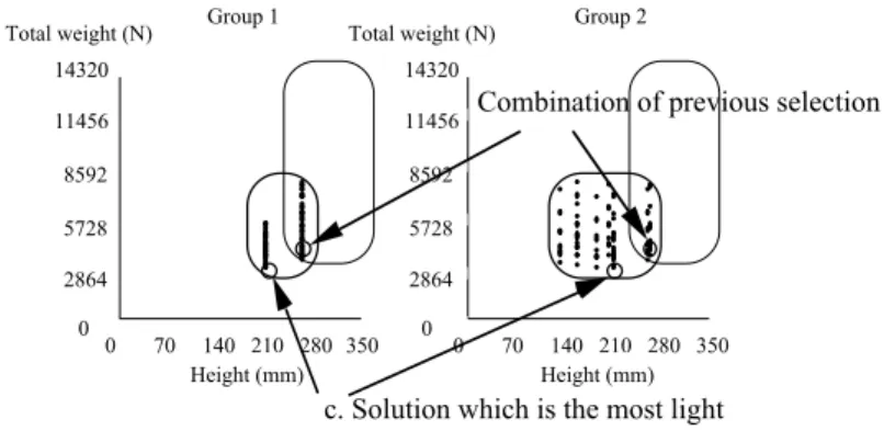
After the performance, the first acquisition of designable space is achieved as shown in Figure 5. The vertical axis in this graph is the total weight of frame, which is designable, and the lateral axis is member height, which is variable for the design. Constrained condition is shown in (1) of Table1. The first chosen member for examination is plotted as a point (a) in Figure 5. Change of member for betterment of design solution is implemented by clicking of another design solution in this designable space. For example, when the lightest frame (b) in Figure 5 is selected, the previous data of each member in the frame is replaced by new value. As a result, all members are refreshed on the data input sheet as shown in Figure 4.
When the designer needs another better solution, the rewritten members are
applied for the next structural analysis and those are examined with the structural
design code. Also the designer takes new constrained condition shown in (2) of
Table 1 for getting lighter designable members. As a result, the designer gets the
new designable space shown in Figure 6. When Figure 5 is compared to Figure 6,
it is shown that the designable space moved in the design space. More rational
reasonable solution for him or her is acquired by selecting a design solution (c) that is the minimum lightweight data set in designable space shown in Figure 6.
Above achieves the process shown in Figure 2 that the pertinent solution is acquired by moving designable space in design space.
Table 1: Constrained condition for acquisition of designable space.
Item Colum (Square steel tube) Beam (H-section)
Height 350 - 250
200 - 100 250 - 0 150 - 0 (1)
(2)
350 - 250 250 - 0 Width
Height Width
mm
mm mm
mm mm mm
Group 1
0 70 140 210 280 350 0
2864 5728 8592 11456 14320 Total weight (N)
0 70 140 210 280 350 0
2864 5728 8592 11456 14320
Group 2 Total weight (N)
Height (mm) Height (mm)
a. Set of assumed frame
b. Select the most light weight combination of cross section in designable space for the previous chosen
Figure 5: Acquisition of designable space (1).
0 70 140 210 280 350 0
2864 5728 8592 11456 14320
0 70 140 210 280 350 0
2864 5728 8592 11456 14320
Group 1 Group 2
Total weight (N) Total weight (N)
Height (mm) Height (mm)