Synthesis and Properties of Li
3VO
4– Carbon Composite as Negative Electrode for Lithium-Ion Battery
Kengo Narumi, Tomoya Mori, Rei Kumasaka, Tomohiro Tojo, Ryoji Inada* and Yoji Sakurai
Department of Electrical and Electronic Engineering, Toyohashi University of Technology, 1-1 Tempaku-cho, Toyohashi, Aichi 4418580, Japan
Abstract. Lithium vanadate Li3VO4 (LVO) is known to be as one of the attractive candidates for negative electrode of lithium-ion battery (LIB) with high safety. Although theoretical capacity of LVO attains to 400 mAh g-1, the actual charge and discharge capacities are far below due to its low electrical and ionic conductivity. In this study, we synthesized carbon-coated LVO (C-LVO) via one-step solid state reaction method and examined its properties as a negative electrode for LIB. From XRD measurements and SEM observation, crystal structure of C-LVO was nearly identical with non-coated one but grain size of former was much smaller than latter with same annealing temperature, suggesting that introduction of carbon source in starting materials effectively helps to suppress LVO grain growth during annealing. TEM observation of C-LVO also shows that amorphous carbon layer with its thickness of several ten nm was formed on the surface of LVO grain. In electrochemical testing, C-LVO shows much higher charge and discharge capacities than non-coated LVO.
Keywords: Lithium ion battery; negative electrode; lithium vanadate; carbon-coating; electrochemical properties.
PACS: 82.47.Aa, 82.45.Xy, 82.45.Fk, 82.45.-h
INTRODUCTION
Rechargeable Li-ion batteries (LIBs) are widely used as a power source for portable electronic devices, and recently have attracted much attention as a large-scale power source for electric vehicles, plugin hybrid electric vehicles and stationary load-leveling system. Graphite is used as the dominant negative electrode in commercial LIB and intercalates Li+ at a low potential close to that for Li-plating, which results in a safety risk due to high surface Li-plating or formation of Li dendrite and short circuits inside the battery to fire the flammable organic liquid electrolyte [13]. Such safety concern has become the critical issue for applications of LIB as large scale power sources. Spinel lithium titanate Li4Ti5O12 (LTO) is another well recognized insertion type negative electrode known for its minimal structure change and high reversibility upon Li+ insertion/extraction [47]. Since Li+ insertion into LTO occurs at 1.51.6 V vs. Li/Li+ with zero strain, it exhibits significantly improved safety performance and cycling stability. However, its low charge and discharge capacities (= 150160 mAh g-1) along with a high operation voltage sacrifices battery energy density seriously.
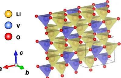
Very recently, lithium vanadate Li3VO4 (LVO) is reported as another attractive candidate for negative electrode of LIB with high safety [810]. Crystal structure of orthorhombic LVO is shown in Figure 1. Due to the two electron transfer reaction per vanadium by redox couple of V5+/V3+, theoretical capacity of LVO attains to 400 mAh g-1 around the potential at 0.51.0 V vs. Li/Li+ [8], which is much higher than that of LTO (= 175 mAh g-1) and comparable with that of graphite (= 372 mAh g-1). Such properties of LVO are suitable to achieve high safety and high energy density of battery simultaneously. However, the actual charge and discharge capacities of LVO are far below than the theoretical one mainly due to its poor electronic conductivity [810].
It is widely known that in generally, the electrochemical performance of electrode materials can be remarkably improved by carbon coating [11], introducing nanostructure and controlling particle morphology [1216]. The former is effective to increase the extrinsic electronic conductivity of electrode material while the latter plays a role in Li+ insertion/deinsertion kinetics, by increasing the reaction interface between the active materials and liquid electrolyte and facilitating transport owing to shorter or simpler Li+ diffusion paths. In this study, we synthesized carbon-coated LVO (C-LVO) via simple one-step solid state reaction method to improve the electronic conducting properties. Crystal phase, microstructure and electrochemical performance for C-LVO were examined and compared with those for carbon-free LVO.
Figure 1 Illustration of crystal structure of orthorhombic Li3VO4.
EXPERIMENTAL
Materials Preparation and Characterization
Carbon-free LVO and C-LVO was synthesized via one-step solid state reaction method. Stoichiometric amount of LiOHH2O (Kojundo Chemical Laboratory Co., Ltd., 99%), V2O5 (Kojundo Chemical Laboratory Co., Ltd., 99.9%) and sucrose as carbon source were ground and mixed for 1 h in acetone in an agate mortar. Ratio of carbon (included in sucrose) to LVO was set to be 15wt%. The mixture was sealed in a quartz tube with alumina boat with low atmospheric pressure of 2 103 Pa and then annealed at 700°C for 11 h using a tube furnace. For comparison, carbon-free LVO was also prepared by annealing the mixture of LiOHH2O and V2O5 at 700°C for 11 h in air.
Crystal phase of obtained samples were identified by X-ray diffractometer (MultiFlex, Rigaku) using CuKα radiation (λ = 0.15418 nm), with measurement angle range 2 = 590° and step interval of 0.01°. Thermo- gravimetric and differential thermal analysis (TG-DTA) of C-LVO was carried out by using differential thermal balance analyzer (Thermo plus EVO II TG-DTA TG8120, RIGAKU) at temperature range from room temperature to 800°C in flowing air with 0.5 L/min, to estimate the actual carbon contents. Both field-emission scanning electron microscope (FE-SEM, SU8000 Type II, Hitachi) and transmission electron microscopy (TEM, JEM-1400, JEOL Ltd.) were used to observe the sample morphology.
Electrochemical testing
For electrochemical characterization of both carbon-free LVO and C-LVO, two-electrode set-up was used.
Firstly, the composite electrodes were fabricated from a mixture of active material (LVO or C-LVO), acetylene black (AB) as a conducting additive, and polytetrafluoroethylene (PTFE) as a binder with the mixing ratio of 70 : 25: 5 in weight. The mixture was rolled into thin sheet with its thickness of 0.3 mm and punched into 8 mm- diameter circular disks. LVO or C-LVO pellet was used as working electrode, where as a single lithium foil serve as both counter and reference electrodes. The electrolyte solution was 1 mol LiPF6 in a mixture or ethylene carbonate (EC) and dimethyl carbonate (DMC) with a volume ratio of 1:1 (Kishida Chemical Co., Ltd.). Together with Celgard 3501 as a separator, these components were assembled in a CR2032 coin type cell. The assembly of the cell was made in a dry Argon-filled glove box (UN-650FCH, UNICO). The cell was charged and discharged over a voltage range of 0.22.5 V at different fixed current density of 0.53.0 mAcm-2 and 20°C using Battery Test System (TOSCAT-3100, Toyo System).
RESULTS AND DISCUSSION
Materials Characterization
XRD patterns of carbon-free LVO and C-LVO are shown in Figure 2. As can be seen, all diffraction peaks for both samples agree well with that for orthorhombic Li3VO4 phase (JCPDS No.38-1247) with the lattice parameters of a = 5.447 Å, b = 6.327 Å and c = 4.948 Å. Other diffraction peaks from secondary phases are hard to confirm. As shown in the insets, the color of fully reacted samples are completely different, in which carbon-free LVO is white while C-LVO is dark black. The carbon contained in C-LVO is expected to have mainly amorphous structure since no peaks attributed to crystalline carbon can be detected in the XRD patterns.
Figure 2 XRD patterns for carbon-free LVO and C-LVO. Figure 3 TG-DTA curves for C-LVO under flowing air.
Figure 4 SEM images for (a) carbon-free LVO and (b) C-LVO. TEM image of C-LVO particle is shown in (c).
Figure 3 shows TG-DTA curves for C-LVO annealed under flowing air. After the measurement, the color of C- LVO was confirmed to be changed from black to white, indicating that the carbon contained in C-LVO is burned off completely. In TG curve, the weight loss is gradually increased with the temperature up to 300C while no reaction peaks were observed in DTA curve, indicating that the weight loss at temperature below 300C is mainly ascribed to the evaporation of moisture. It is confirmed that the DTA curve has a large exothermic peak around 360C and a small exothermic peak around 640C. With taking into account the DTA curve, the weight loss above 300C is attributed to the combustion of the carbon contained in C-LVO. The former is attributed to the combustion of amorphous carbon while the latter is due to the combustion of graphitized carbon [17]. The carbon content in C- LVO is estimated to be 3 %. The weight loss at temperature from 300 to 500C is much larger than that at temperature above 600C, so that the carbon contained in C-LVO has mainly amorphous structure.
Figure 4(a-b) shows SEM images of carbon-free LVO and C-LVO. As shown in Figure 4(a), carbon-free LVO has non-uniform particles withthe particle size of 15 m. On the other hand, the particle size of C-LVO is 0.20.5
m and some particles are agglomerated to form micron-sized secondary particles (Figure 4(b)). It is worth to note that as preliminary experiment, we synthesized carbon-free LVO by annealing the starting materials without carbon source under low atmospheric pressure, but its particle size is not different so much with carbon-free LVO annealed in air in Figure 4(a). Therefore, such remarkable change of the particle morphology is mainly attributed to the introduction of the carbon source in starting materials.
High-resolution TEM image for C-LVO is also shown in Figure 4(c). Lattice fringes are clearly observed in the crystalline region with the inter-planar spacing about 0.54 nm, which can be indexed to (1 0 0) plane of the orthorhombic Li3VO4. In addition, an amorphous carbon layer with the thickness around 10 nm can be clearly observed on the particles, which contributes to suppress the LVO grain growth during heat treatment for sample preparation and also to improve the electronic conductivity as well as to enhance the electrochemical performance of electrode as described in later.
Electrochemical Properties
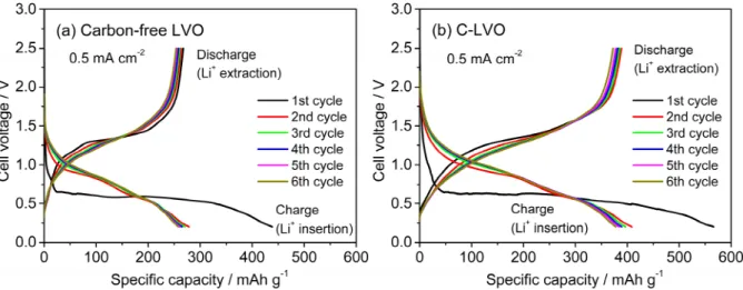
Figure 5 shows the charge and discharge curves from the first to the sixth cycle for carbon-free LVO and C-LVO measured at the current density of 0.5 mA cm-2. As shown in Figure 5(a), Carbon-free LVO delivers a charge (Li+ insertion) capacity of 437 mAh g-1 and a charge (Li+ extraction) capacity of 270 mAh g-1 at the first cycle. The charge capacity is much larger than the discharge one and an initial coulombic efficiency at the first cycle are 61%.
Furthermore, the cell voltage profile in the charge process is quite different from the profile after second cycle.
These phenomenon are mainly caused by the side reactions such as the decomposition of the organic liquid electrolyte, the formation of solid electrolyte interface (SEI) film at the electrode and electrolyte interface [3, 8], the instability in initial Li+ insertion reaction and phase transformation [9, 1820] in the first charge process. After the second cycle, the electrode reaction shows a high reversibility as the third to sixth cycles can well repeat both the curve shape and the specific capacity of the second cycle, but the reversible capacity after the second cycle (=
250260 mAh g-1) is much lower than theoretical capacity of LVO (= 400 mAh g-1) corresponding to two Li+ insertion reaction into LVO expected by V5+/V3+ redox couple [8]. On the other hand, C-LVO delivers much larger charge and discharge capacities of 570 mAh g-1 and 395 mAh g-1 at the first cycle, corresponding an initial coulombic efficiency of 69%. After the second cycle, the electrode reaction of C-LVO also shows a reversible charge and discharge performance as well as carbon-free LVO but C-LVO delivers much larger specific capacity around 390 mAh g-1 (Figure 5(b)), which is nearly the same level as the theoretical capacity as mentioned above and 2 times or more greater than the capacity of LTO.
For further examination of the electrochemical performance, the charge and discharge curves for both carbon- free LVO and C-LVO at various current density of 1.0, 2.0 and 3.0 mA cm-2 are also shown in Figure 6. Both samples are charged and discharged three cycles at 0.5 mA cm-2 before the measurements of current density dependence. As can be seen, charge and discharge capacities for both samples are monotonically decreased with increasing the current densities, due to the increase of the polarization in electrode reaction with operating current densities. However, comparing at the same current density, C-LVO delivers significantly higher charge and discharge capacities than carbon-free LVO. Nano-sized carbon layer on C-LVO particle plays a role to enhance the electric conductivity in pelletized composite electrode and smaller grain size of C-LVO is also preferable for both increasing the reaction interface between the electrode active material and liquid electrolyte and facilitating Li+ insertion and extraction reactions owing to shorter and simpler Li+ diffusion paths. Consequently, C-LVO shows much superior electrochemical performance to carbon-free LVO.
C-LVO synthesized by a simple one step solid state reaction method is an attractive candidate as a negative electrode material in high safety LIB for large scale applications, but in C-LVO prepared in this work, strongly agglomerated particles are still contained as shown in Figure 3(b). The agglomeration of LVO nanoparticles possibly reduces the interface between electrode material and liquid electrolyte and deteriorates electrochemical performance particularly at high current density operation. Therefore, we believe that further improvement of electrochemical performance of C-LVO is possible by optimizing synthesis condition (processing method, carbon source, etc.) to suppressing the agglomeration of LVO particles.
Figure 5 Charge and discharge curves at fixed current density of 0.5 mA cm-2 for (a) carbon-free LVO and (b) C-LVO.
Figure 6 Charge and discharge curves at current densities of 1.0, 2.0 and 3.0 mA cm-2 for (a) carbon-free LVO and (b) C-LVO.
CONCLUSION
Carbon-coated Li3VO4 (C-LVO) was successfully synthesized via one-step solid state reaction method and its properties as a negative electrode for LIB were investigated. Crystal structure of C-LVO was nearly identical with non-coated LVO but grain size of the former was much smaller than the latter with same annealing temperature, indicating that introduction of carbon effectively helps to suppress LVO grain growth during annealing. TEM observation of C-LVO also shows that amorphous carbon layer with its thickness of several ten nm was formed on the surface of LVO grain. C-LVO shows much better electrochemical performance than non-coated LVO.
According to these results, C-LVO can potentially be used as negative electrode material for high safety LIB for large scale applications.
ACKNOWLEDGMENT
This work was partly supported by TOYOAKI Scholarship Foundation.
REFERENCES
1. J.M. Tarascon and M. Armand, Nature 414, 359-367 (2001).
2. B. Scrosati and J. Garche, Journal of Power Sources 195, 2419-2430 (2010).
3. J.B. Goodenough and Y. Kim, Journal of Power Sources 196, 6688-6694 (2011).
4. Z. Chen, I. Belharouak, Y.-K. Sun and K. Amine, Advanced Functional Materials 23, 959-969 (2013).
5. T. Ohzuku, A. Ueda and N. Yamamoto, Journal of The Electrochemical Society 142, 1431-1435 (1995).
6. D. Yoshikawa, Y. Kadoma, J.M. Kim, K. Ui, N. Kumagai, N. Kitamura and Y. Idemoto, Electrochimica Acta 55, 1872- 1879 (2010).
7. M.S. Song, A. Benayad, Y.M. Choia and K.S. Park, Chemical Communications 48, 516-518 (2011).
8. H. Li , X. Liu , T. Zhai , D. Li and H. Zhou, Advanced Energy Materials 3, 428-432 (2012).
9. W-T. Kim, Y.U. Jeong, Y.J. Lee, Y. J. Kim and J.H. Song, Journal of Power Sources 244, 557-560 (2013).
10. W-T. Kim, B-K. Min, H.C. Choi, Y.J. Lee and Y.U. Jeong, Journal of The Electrochemical Society 161, A1302-A1305 (2014).
11. J.T. Han, Y.H. Huang and J.B. Goodenough, Chemistry of Materials 23, 2027-2029 (2011).
12. K. Tang, X.K. Mu, P.A. Aken, Y. Yu and J. Maier, Advanced Energy Materials 3, 49-53 (2012).
13. L. Fei, Y. Xu, X. Wu, Y. Li, P. Xie, S. Deng, S. Smirnov and H. Luo, Nanoscale 5, 11102-11107 (2013).
14. C. Jo, Y. Kim, J. Hwang, J. Shim, J. Chun and J. Lee, Chemistry of Materials 26, 3508-3514 (2014).
15. S. Jayaraman, V. Aravindan, P.S. Kumar, W.C. Ling, S. Ramakrishna and S. Madhavi, ACS Applied Materials & Interfaces 6, 8660-8666 (2014).
16. B. Guo, X. Yu, X.G. Sun, M. Chi, Z.A. Qiao, J. Liu, Y.S. Hu, X.Q. Yang, J.B. Goodenough and S. Dai, Energy &
Environmental Science 7, 2220-2226 (2014).
17. S. Hu, Y. Song, S. Yuan, H. Liu, Q. Xu, Y. Wang, C-X. Wang and Y-Y Xia, Journal of Power Sources 303, 333-339 (2016).
18. S. Ni, X. Lv, J. Ma, X. Yang and Lulu Zhang, Journal of Power Sources 248 122-129 (2014).
19. Z. Liang, Y. Zhao, L. Ouyang, Y. Dong, Q. Kuang, X. Lin, X. Liu, D. Yan, Journal of Power Sources 252 244-247 (2014).
20. Z. Liang, Z. Lin, Y. Zhao, Y. Dong, Q. Kuang, X. Lin, X. Liu, D Yan, Journal of Power Sources 274 345-354 (2014).