�������� ��������������� �� ��������
�� � �
������������
�� � �
����
Nb
3
Sn �����
��� ��
�
�
Nb
3Sn Conductor Development for Fusion Power Applications
Toshinari ANDO
Synopsis: The progress of Nb3Sn conductor development for fusion power applications at JAERI is described. The
superconductor development was carried out in connection with the research and development for four fusion coil development projects: Phoenix, Cluster test, Demo Poloidal Coil and ITER-EDA. In the Phoenix project, the reliable production of multi-filamentary Nb3Sn strands was established during the development work towards realizing a 18 T coil, and an 18 T
generation coil (BC-18) with multi-filamentary Nb3Sn strands was successfully operated at 4.2 K for the first time in the world.
In the Cluster Test project, a pool-cooled Nb3Sn conductor with a high heat-flux surface, and the first 1-m class bore Nb3Sn coil
(TMC) in the world was constructed and operated up to 12 T. In the Demo Poloidal Coil project, which was constructed to demonstrate the possibility of a poloidal coil, a forced-cooled Nb3Sn conductor was developed. The Nb3Sn coil (DPC-EX)
constructed with it was pulse-operated up to 7 T in 0.5 s. Finally, in the ITER-EDA project a CICC-type 13 T-46 kA Nb3Sn
conductor was developed. A Central Solenoid Model Coil (CSMC) was fabricated using it and successfully operated up to 13 T with 0.4 T/s.
Keywords: Nb3Sn conductor, high field, CIC conductor, fusion, ITER
���������
Nb3Sn ��������������������� ������������ 1975 ����������� �������������������������� ��������JT-60�����TFTR�����JET�EU� �������������������������� ������ITER ����������������� �������������������������� ����������������������TF��� ��������NbTi ������ 7�8 T ������ �������������������������� ������4.2 K ���������� 11 T ����� �������������Nb3Sn ���������� �������12 T ����������������� Nb3Sn ����������������������� �������������������������� �������������������������� �������������4 ������������ ����������������� ��������Nb3Sn �������������� ��������������������IGC ���� �������������������RCA ����� �����������IGC � 15.8 T ��������� ������1�����Nb 3Sn ������������ �������������������������� �������������������������� ���1977 ��������������������� ���������������Nb3Sn �������� ���������������� ITER ������� ���������������� ���������������
������������������������� �������������������������� �������������������������� �������������������������� �������������������������� �������������������������� ������� ����100 kA ���16�20 T ���� � � ���������500�1000 mJ/cc � � � � � � � � � � � at +/- 3 T cycle Received July 12, 2004 ���������������� �311-0102� ����������� 801Nippon Advanced Technology Co., Ltd., 801 Mukouyama, Naka-machi, Naka-gun, Ibaraki 311-0102, Japan E-mail:ando@naka.jaeri.go.jp
��� �����0.5�1 s ����10 ��������������� ������ 1000 A/mm2 �������100 MPa � ��������������������������� �������������������������� �������������������������� ��������������������������� �������������������������� �������������������������
�����
��� ��������������������
Hancox2������������Flux jump free���� � Supercon �������������������� ���������� NbTi ������������� �����������Nb3Sn ������� Kaufman � 3)�����������������������1965 ���1970 ��������������������� ���4, 5)���������������������� �������������������������� �������������������������� ����������������,���� Nb3Sn �� �������������������������� �������������������������� ��������������������������1 kA ������������������� ����� ����������Nb3Sn ������������� ���������������������100 mm � 10 T �������������������6)� ������������������������ �������������������������� ������1 mm x 10 mm ���������� Nb3Sn ������Fig. 1 ��������������/��� ������������������������10 %
Fig. 1 Cross-section of the MF Nb3Sn conductor used for the
BC-10 coil. (a) Overall (upper) and (b) Nb3Sn filaments (lower).�
Fig. 2 The first Nb3Sn coil (BC-10) fabricated at JAERI in
1979 using the conductor shown in Fig. 1.�
�������������������������� 2 ��������� Table 1 ������������� �����������Fig. 2 ����1979 ������ �240 mm �� 8 T ����������������� ��������������10 T ���������� �������������Nb3Sn ������ 10 T �� ���������1980 ��������������� 11 T ������������� ������������������������� ���������Phoenix ���7)�1982 ��� 13 T� 1985 ��� 15 T���� 1990 ��� 18 T ������� �����������18 T ���������� 4.2 K ����18 T ������������� Nb3Sn ���� ��18 T �������8)�������������� �����Fig. 3 � Fig. 4 ������ Nb3Sn ����� �������������������������� ��Table 2 ������ Nb3Sn ����������� ���������3 � 1 ����non-Cu Jc�1500 A/mm2 at 12 T ���������������������� Phoenix ��������� Nb3Sn ���������� ���������18 T ��������������� ���������� ������Nb3Sn ���������������� ���������1 m ���������������
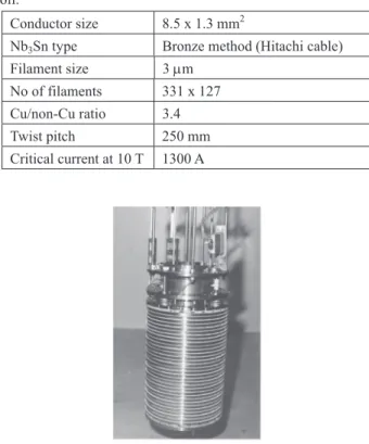
Table 1� Parameters of the Nb3Sn conductor for the BC-10
coil.
Conductor size 8.5 x 1.3 mm2
Nb3Sn type Bronze method (Hitachi cable)
Filament size 3 �m No of filaments 331 x 127 Cu/non-Cu ratio 3.4 Twist pitch 250 mm Critical current at 10 T 1300 A
Fig. 3 Cross-section of the MF Nb3Sn conductor used for the
BC-18 coil.�
Fig. 4 BC-18 coil, the first Nb3Sn coil operated up to18 T at
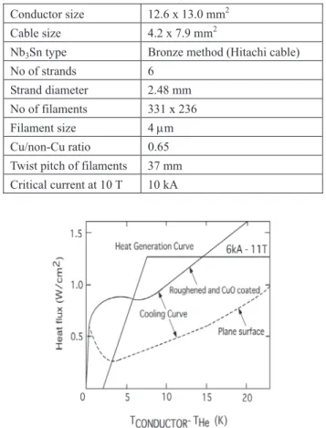
4.2 K in the world.� �����������9) �������������� �����������TMC�����2 ������� �������������������������� ��������TMC ���� Fig. 5 ������ 2.3 mm ����Nb3Sn �� 6 ��������� Nb3Sn ���� ��650�� 200 ������������������ �������������������������� ���������Table 3 ������������� �������������������������� ������������Fig. 6 ����������� �������������������������� �������2 ������������������ ����6
Fig. 5 Cross-section of a Nb3Sn conductor used for the TMC
coil.�
Fig. 6 Heat flux curve of the Nb3Sn conductor for TMC.�
�������������������������� ������������������������� ������������������� 0.7����� Nb3Sn ������� TMC ����Fig. 7���� 12 T � ������������ ������ Nb3Sn ��������������� ���������������������Fig. 8 �� �������������������������� ���TRIUM-1M10��MFTF-B11)�Nb 3Sn ������� ����������������
����� ��������
���
�������������������������Table 2� Parameters of the Nb3Sn conductor for the BC-18
coil.
Conductor diameter 2.07 mm
Nb3Sn type Tube method (by Showa)
Filament size 109 �m No of filaments 180 Cu/non-Cu ratio 1.0 Critical current at 18 T 600 A
Table 3� Parameters of the Nb3Sn conductor for TMC.
Conductor size 12.6 x 13.0 mm2
Cable size 4.2 x 7.9 mm2
Nb3Sn type Bronze method (Hitachi cable)
No of strands 6 Strand diameter 2.48 mm No of filaments 331 x 236 Filament size 4 �m Cu/non-Cu ratio 0.65 Twist pitch of filaments 37 mm Critical current at 10 T 10 kA
Fig. 7 TMC in which 12 T was generate with a 600 mm bore
at 6 kA.�
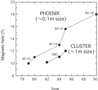
Fig. 8 The progress of the JAERI Phoenix project,
small-scale, high-field Nb3Sn coil development project, the
Cluster test project, and the large Nb3Sn coil development
project.� ��������TF������� 10 kA ������� �������������������������� �������������������������� �������������������������� �����PF�������������������� 1 mm ����������������������� �����–��–������CIC���������� ������� CIC ��� 1975 �� MIT � Hoenig �12) ��������� ��� 1976 ����������� ������������FER�� TF ��������� ��������� FER �������������� �������������������� R&D �� �LCP������ IEA��������������� �����������LCT�������������
Fig. 9 The structure of the CIC conductor and its progress.�
�����6 ������ 1 �� LCT-W ������� �Nb3SnCIC ��������13)��������Fig. 9 �����0.7 mm �� Nb3Sn �� 486 ��� JBK-75 �� �������������������������� �� 8 T ������������ 5 ��������� ���������������Ic���������� ���������������������PF ���� ��������������������CIC ���� �������������������������� �������������������������� ��14)�������������������� ���� PF ������������������� ������DPC������������� Nb3Sn �� ����PF ��������� DPC-EX ������� ����������CIC �������������� ���LCT-W � Nb3Sn ��������������� �����Nb3Sn ������������������ �������������������������� �������������������������� �������������������������� �������������������������� �������������������������� �������������������������� �������������������������� ������������7 T ���� 0.5 ������ �����������15)� DPC ���� CIC ���� ���Hoenig �����������US-DPC����� �����������16)�������������� ������Incoloy 908 ����������Incoloy 908 ���������������Nb3Sn �������� ��������������������Nb3Sn ��� ��������������������������� ����������������������� Fig. 9 �����Nb3Sn CIC �������������� ��
�������� � CIC ����������������������� �������������������������� �������������������������� ���������� 1 km ������������� ����������������Nb3Sn ������� �������������������������� ��� 10 m �������������������� �����������������������2 �� �����Nb3Sn ������������������ �������������������������� ������ � ���� ������ ������������������������� �������������������������� �������Nb3Sn ��� 600����������� �������������������������� �Nb3Sn ���������������������� ����������������������� Nb3Sn CIC ����� LCT-W ��������������� ����� Nb3Sn ����������������� �������������������������� ����������� 10 ����������� MIT �������������1 �m ���������� �������������������1 �m ���� ����������17)�����2 �m ������� ���������Fig. 10 �������������� ������������� � � � � � � � � � � � � � � � � � � � � �
Fig. 10 The time constant of strand coupling in the CICC vs.
void fraction for thickness of chrome plating.�
���� ������� CIC ����������������������� ���������������Nb3Sn �������� �������������������������� ���Nb3Sn �������������������� Nb3Sn ������� 923 K ������������� �5 K ������������������� Nb3Sn � ������������������Nb3Sn ����� �����������������������0.84� ������ Nb3Sn �����������Fig. 11 �� Nb3Sn�316LN�������� 908�����JK2 ��� �����������908 � Nb3Sn CIC ������� ����MIT ����������������Nb3Sn � �������������������������� �����������������SAGBO������ �������������������� Nb3Sn ��
Fig. 11 Thermal contraction vs. temperature for various
conduit materials.
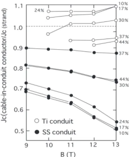
Fig. 12 The influence of conduit material on Jc for various
void fractions.
����������������316LN ������� ������������2 ������������� ���JK218)��������4.2 K ��� 316LN ��� ���������5 K �������� 316LN ���� ������������CS������������� ������������������Fig. 12 ����� ����������� Nb3Sn CIC ������ Jc�� �����19)�������������������� �������Jc������13 T ���������� �������������������������Jc ���������Nb3Sn �������������� �������������������������� 13 T �����������������������16 T ������������ Jc������������ ������������������ � ���� ������� � Nb3Sn ���������������������� �������������������������� ��������Nb3Sn ��������������� ����Nb3Sn ������������������� �������������������������� �������������������������� �������������������������� �����������������Jc�������� �������������������������� ������������������
�� �������� ���
� ITER �������������ITER-EDA������ ITER ���������������������MC� ��������������MC ������ CSMC� TFMC�CS ������TF ���������� Nb3Sn �����������CSMC ���� Fig. 9 ����� ��������������������������� CSMC � CS ������� Incoloy 908 ��TFMC �� 316LN ��TF �������������������� ���Nb3Sn ������������� Fig. 11 ���� ��������� � ������������������������� Nb3Sn ������ Table 4 ���������� 4 ��� �����4 �������������������� ����Nb3Sn �����������ITER-EDA ��� �������������������������� �������������������������� ���4.2 K�12 T �� ITER ��� Jc��������� ������������ 650����� VAC���� EAS ��������������� 2 �������� �������� � ITER-EDA �����������������Nb3Sn ��������3 ����������� � ���� ������ � ����������CIC ������������� �������������������������� ������������������������ 4.2 K �����������������ITER ������ ��0.7 K ��������������������� ��������������������� ITER �� ���5.7 K ����� Jc�����������4.2 K �������������������������� �������Fig. 13 � ITER � R�D �������� � � � � � � � � � � � �Fig. 13 The critical current density vs. temperature for
various strand manufacturers.�
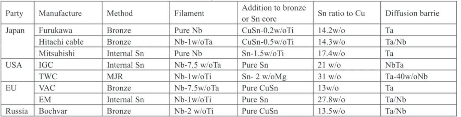
Table 4� Characteristics of the Nb3Sn strands used in the ITER-EDA model coils
Party Manufacture Method Filament Addition to bronze or Sn core Sn ratio to Cu Diffusion barrie Japan Furukawa Bronze Pure Nb CuSn-0.2w/oTi 14.2w/o Ta
Hitachi cable Bronze Nb-1w/oTa CuSn-0.5w/oTi 14.3w/o Ta/Nb Mitsubishi Internal Sn Pure Nb Sn-1.5w/oTi 17.4w/o Ta USA IGC Internal Sn Nb-7.5 w/oTa Pure Sn 21 w/o NbTa
TWC MJR Nb-1w/oTi Sn- 2 w/oMg 31 w/o Ta-40w/oNb EU VAC Bronze Nb-7.5w/oTa Pure CuSn 13w/o Ta
EM Internal Sn Nb-1w/oTi Pure Sn 27.8w/o Ta/Nb Russia Bochvar Bronze Nb-2 w/oTi Pure CuSn 13.5w/o Ta/Nb
Operating cycle
Fig. 14 The time constant of coupling current in the CSMC
conductor vs. operating cycle of the CSMC.�
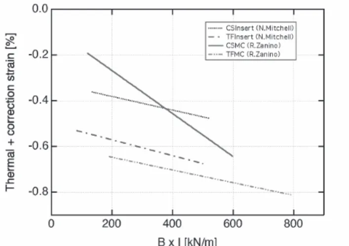
��������Jc���������20)������� ����IGC � EM � 4.2 K ���� Jc�������� ����������������Hitach cable � Bochvar ��Jc������� Tcs����������Jc��� �������������������������� ������Nb3Sn ����������������� ��������������������Jc����� ����������� ���� �������������������� � Nb3Sn ���������������������� �������������������������� ��� �Fig. 14�21)������������������ �������,������������������� �������������������������� �������������������������� �� 0.1%��������������������� �������������������������� ���������� � ���� ������������������� � �������� �� ����� ���������������� �������������������������� ������������������������� Correction strain�� Fig. 15 ������������� Nb3Sn ������������������������
Fig.15 Additional strain in the function of the electromagnetic
force (B x I).� ����22���������������������� �������������������������� �����Nb3Sn ����� Nb3Sn ���������� �������������������������� �������������������������� �����ITER �������� Jc��������� ��������������
�� ��� ��
��� ���������
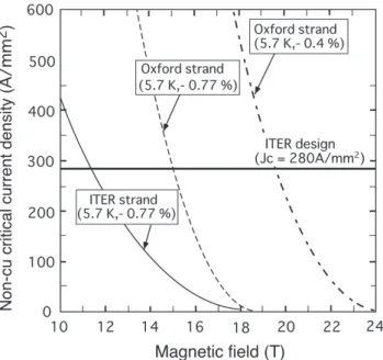
����Nb3Sn ������ Table 5 �������� ����������������� ITER ������ �������������������������� �Nb3Sn ���������������������� ������������������Nb3Sn ����� �������������������Nb3Sn ���� ���������������������� Oxford �������Jc��3000 A/mm2 at 4.2 K�12 T�� Nb3Sn �23)�������������ITER �������� �Nb3Sn ���������������������� ���������Fig. 16 ����ITER ������� ����������������5.7 K�������� –0.77 %������� ITER � TF �������� 11.8 �Table 5� Progress of the Nb3Sn large current capacity conductors developed for fusion
TMC
(1982)* (1986)* LCT-W (1990)* DPC ITER-EDA(1998)* ITER Nb3Sn type Pure Nb3Sn Pure Nb3Sn Alloyed Nb3Sn
(In, Ti) Alloyed Nb(Ti, Ta) 3Sn Alloyed Nb(Ti, Ta) 3Sn
Jc at 12 T, 4.2 K 360 A/mm2 350 A/mm2 420 A/mm2 550~700 A/mm2 700~800 A/mm2
Hysteresis loss (±3 T) 400 mJ/cc 400 mJ/cc 300~460 mJ/cc 200~600 mJ/cc 400~600 mJ/cc Diffusion barrier Nb Nb Ta, V Ta, Ta /Nb Ta, Ta /Nb Surface coating material - No coating Cr Cr Cr
Conduit material - JBK-75 Incoloy 908, JK-1 Incoloy 908, 316LN 316LN, JK-2 * year when the coil was firstly operated
�� � � � � � � � � � � � � � � � �
Fig. 16 Consideration of the applicability of Nb3Sn conductor
to high-field coil for fusion.�
T �� Jc�280 A/mm2����Oxford �� Nb3Sn ���� ���ITER ������������������� 15 T �������������������������� ��������–0.4%������������� 19 T ��������������Jc����������� ������������ Tc(B) ���������� Nb3Sn ���������������������� Jc ���Tc�Bc2����������������
�� �����
����Nb3Sn ������������������ �������������������������� ���������������ITER ����� TF �� ��CS � Nb3Sn ����������������Nb3Sn �������������������������� �������������������������� ����������������� ������������������������� ����������� �� �� �
1) W.A. Fietz, et al.: “Superconducting Nb3Sn solenoids operating at 15-16.5 T,” IEEE Trans. on Mag. MAG-11 (1975) 559-562 2) R. Hancox: “Stability against flux jumping in sintered Nb3Sn,”
Phys. Lett. 16 (1965) 39-40
3) A.R. Kaufman and J.J. PickettK: “Multifilament Nb3Sn superconducting wire,” Bull. Am. Phys. Soc. 15 (1970) 838 4) Z.J.J. Stekly and J.I. Zar: “Tstable superconducting coils,” IEEE
Trans. Nucl. Sci. NS-12 (1965) 367-376
5) P.F. Smith, et al., “Experimental and theoretical studies of filamentary superconducting composites,” Rutherford Laboratory Preprint, RPP/A73 (1969)
6) E. Tada, et al.: “Realization of 10 T multifilamentary Nb3Sn Magnet System,” presented at the workshop on high field superconducting materials for fusion (1980)
7) T. Ando, et al.: “Development of high field superconducting coil for the tokamak fusion machine in Japan,” Proc. 11th Symp. on fusion Eng. (1986) 991-1000
8) M. Nishi, et al.: “Development of a compact 18-T MF (NbTi)3Sn,” IEEE Trans. on Mag. 27 (1991) 2280-2283
9) T. Ando, et al.: “Experimental of 10-T, 60-cm-bore Nb3Sn test module coil (TMC-I) in the cluster test facility,” IEEE Trans. on Mag. MAG-19 (1983) 312-315
10) S. Itoh, et al.: “Initial operation of the high field superconducting tokamak TRIUM-1M,” Proc. 11th Int. Conf. on plasma physics and controlled nuclear fusion research IAEA, Vienna (1987) 321-331
11) T. Kozman, et al.: “Construction and testing of the mirror fusion test facility magnets,” IEEE Trans. on Mag. MAG-23 (1987) 1448-1463
12) M.O. Hoenig and D.B. Montgomery: “Dense supercritical-helium cooled superconductors for large high field stabilized magnets,” IEEE Trans. on Mag. MAG-11 (1975) 569-572
13) P.A. Sanger, et al. “The Nb3Sn forced flow conductor for the large coil program,” Proc. 11th Symp. on Eng. Prob. of fusion (1981) 1333-1336
14) J.W. Lue, et al.: “Stability of cable-in-conduit superconductors,” J. Appl. Phys. 51 (1980) 772-783
15) T. Ando, et al.: “Experimental result of the Nb3Sn demo poloidal coil (DPC-EX),” IEEE Trans. on Mag. 27 (1991) 2060-2063 16) M.M. Steeves, et al.: “The US-DPC, apoloidal coil test insert for
the Japanese demonstration poloidal coil test facility,” IEEE Trans. on Mag. 24 (1988) 1307-1310
17) T. Ando, et al.: “Effect of chrome plating on coupling losses in a Nb3Sn cable-in-conduit conductor,” J. Cryo. Soc. Jpn. 22 (1987) 362-367 (in Japanese)
�������Nb3Sn ������������������ ���������������� 22 (1987) 362-367
18) H. Nakajima, et al.: “New cryogenic steels and design approach for ITER superconducting magnet system,” Proc. of ICONE 10th International Conf. Nucl. Eng. Arlington, VA, USA, April 14-18 (2002)
19) T. Ando, et al: “The effect of Ti conduit on the critical current in (NbTi)3Sn cable-in-conduit conductor,” IEEE Trans. Appl. Supercond. 3 (1993) 488-491
20) The ITER-JCT final reports on the 2. round of strand bench mark, compiled by P. Bruzzone (1995)
21) N. Martovetsky, et al: “Test of the Central Solenoid Model Coil and CS insert,” IEEE Trans. Appl. Supercond. 12 (2002) 600-605 22) K. Okuno: “Progress at the superconducting magnet technology
through the ITER CS model coil program,” IEEE Trans. Appl. Supercond. 14 (2004) 1376-1381
23) J.A. Parrell, et al: “Nb3Sn conductor development for fusion and particle accelerator application,” M1-M-04, presented at CEC-ICMC 2003, Anchorage �� �� �� �� � ��43����������������� �����������4������������������52 �����������������12����������� ������������������������������ ����������������������������