misalignment tolerance of pluggable ballpoint-pen interconnects, where graded-index plastic optical fibers (GI POFs) are coupled with ball lenses mounted on their end faces. The lateral-misalignment tolerance of the ballpoint-pen connector decreased with an increase in the driving cur- rent of a vertical cavity surface emitting laser (VCSEL) under the center launching condition. This was attributed to the VCSEL multimode oscilla- tion, which increased the connector coupling loss through the higher-order guided mode launching in the GI POF and the resulting output beam ex- pansion in the ballpoint-pen connector. The driving-current dependence of the connector coupling loss could be decreased using offset launchings. For a radial launching offset of 20μm, we could obtain coupling losses below 1 dB for lateral coupling offsets of±50μm with little dependence on the driving current. This suggests that data transmission quality for misaligned connection of the GI POFs can be improved further by optimizing launch- ing systems for the ballpoint-pen interconnects.
key words: graded-index plastic optical fiber, ballpoint-pen interconnect, pluggable optical cable, 4K/8K UHD display
1. Introduction
Recently, ultra-high definition (UHD) displays have been rapidly developed for video formats with 4K (3840×2160) and 8K (7680×4320) resolutions. In Japan, 4K/8K broad- casts through satellites are scheduled for the 2020 Tokyo Olympics and Paralympics, based on a road map announced by the Ministry of Internal Affairs and Communications[1].
This is accelerating research and development of distribu- tion technologies to enable consumers to watch 4K/8K UHD TV at home through satellite, cable television, and internet protocol television. Current UHD displays require uncom- pressed video data transfer from set-top boxes and smart- phones. For 8K video transmission, the data rates can be increased up to∼240 Gb/s[2], suggesting that the interface cables for consumers require extremely high transmission speeds in the upcoming 4K/8K era. Conventional metal in- terfaces such as serial digital interfaces are not suitable for in-home applications because they require many thick ca- bles and electromagnetic interference prevention methods, without which the throughput of wireless networks can be considerably degraded.
A graded-index plastic optical fiber (GI POF) has been a promising transmission medium for in-home networks be-
Manuscript received February 29, 2016.
Manuscript revised June 7, 2016.
†The authors are with the Graduate School of Science and Technology, Keio University, Kawasaki-shi, 212–0032 Japan.
a) E-mail: [email protected] b) E-mail: [email protected]
DOI: 10.1587/transele.E99.C.1271
width[3], [4]. Transmission speeds with a GI POF have been increased up to 40 Gb/s for a length of 100 m with the development of low-dispersive polymers and GI profile con- trol techniques[5]–[8]. Moreover, GI POFs have noise re- duction effects, which are closely related to intrinsic mode couplings in GI POFs[9]–[12]. These properties of GI POFs allow for a low-cost optical module without an optical iso- lator and angled fiber end faces. However, appropriate in- terconnects of GI POFs for consumer applications have not yet emerged.
Recently, we developed consumer-friendly pluggable interconnects of GI POFs based on ballpoint-pen technolo- gies[13]–[15] enabling easy connection, low-cost produc- tion, and fiber end face protection of GI POFs. In the ballpoint-pen interconnect, the output beam from the GI POF is expanded and collimated through the ball lens that is mounted on the fiber end face using ballpoint-pen pro- duction technology. In actual optical systems, however, the misalignment tolerance of the ballpoint-pen connector de- pends on launching conditions because the collimated out- put beam characteristics are determined by launched guided modes in the GI POF. For a multimode vertical cavity sur- face emitting laser (VCSEL), the ballpoint-pen connector performance can be influenced by a change in laser driving current, on which oscillation modes of the VCSEL depend.
In this paper, the dependence of the misalignment tolerance of the ballpoint-pen interconnect on launching conditions with a multimode VCSEL is investigated. The lateral-offset dependence of the coupling loss is evaluated for different driving currents and launching beam positions to obtain de- sign guideline of the ballpoint-pen interconnect in data com- munications with multimode VCSELs.
2. Launching System
2.1 Experimental Setup
In the ballpoint-pen interconnect a ball lens is mounted on a GI POF end face for ball-lens coupling of GI POFs, as shown in Fig. 1 (a). The connector production technology is based on the simple and low-cost ballpoint-pen technol- ogy. First, a metal ball and an ink case are replaced with a glass ball and a GI POF in a needle-tip type ballpoint pen, respectively. Then, the metal sleeve is punch-processed to keep the distance between the GI POF and the ball lens precise for the output beam collimation. After that, the GI Copyright c2016 The Institute of Electronics, Information and Communication Engineers
Fig. 1 (a) Schematic structure of ballpoint-pen interconnect. (b) Experi- mental setup.
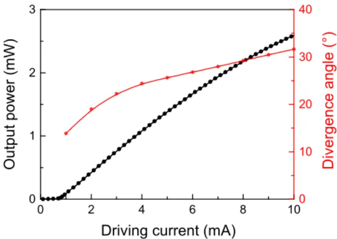
Fig. 2 Output power and far-field divergence angle of the VCSEL as a function of the driving current. The divergence angles are full far-field angles defined in terms of second-order intensity moments[16].
POF is fixed using clamps on the outside of the sleeve. This ballpoint-pen connector significantly increases tolerance for misalignments of the GI POF axes, caused by the expanded and collimated output beam. As shown in Fig. 1 (b), we evaluated coupling characteristics of 1 m GI POFs with the ballpoint-pen connector using a multimode VCSEL with os- cillation wavelengths around 850 nm. The ball lenses in the ballpoint-pen connector have a refractive index of 1.51, a diameter of 550μm, and an effective focal length (EFL) of 407μm. The core diameter and the numerical aperture (NA) of the GI POF were 80μm and 0.25, respectively.
Figure 2 shows output power and far-field divergence angle of the VCSEL as a function of the driving current.
Higher driving currents resulted in wider divergence angles because of the oscillation of higher-order transverse modes.
Because the divergence angles were larger than the NA of the GI POF for driving currents, above ∼7.5 mA, we col- limated and focused the output beam from the VCSEL to decrease the divergence angles for efficient coupling into the GI POF (Fig. 1 (b)). The NA of the collimating lens was 0.68, which was much higher than those of the VCSEL driven at currents below 10 mA. The focal lengths of the collimating lens and the focusing lens were 3.1 and 6.2 mm,
on input fiber end faces (top) and the enlarged images of the beam patterns (bottom) for driving currents of (a) 2 mA, (b) 5 mA, and (c) 8 mA. Both the scale bars are 10μm.
respectively. These allowed for under-filled launching con- ditions with sufficiently high coupling efficiencies into the GI POF with comparable coupling losses to the Fresnel re- flection losses on the input end face of the GI POF.
2.2 Launching Condition with Multimode VCSEL Figure 3 shows microscopic images of launching beam pat- terns on input fiber end faces for several driving currents.
The blurred images of fiber end faces were due to the chro- matic aberration of the imaging system. The significantly- changed beam patterns were observed with an increase in the driving current. The corresponding beam quality pa- rameters of M2 values were 2.9, 4.3, and 5.0 for driving currents of 2 mA, 5 mA, and 8 mA, respectively. Because of these different beam patterns, higher driving currents re- sult in more guided modes in the GI POF and thus a more expanded beam from the ballpoint-pen connector. This sug- gests that the misalignment tolerance of the ballpoint-pen interconnect can be influenced by the driving current change of the VCSEL.
Using the ballpoint-pen-coupled GI POFs without the connector misalignment, the relative system transmission loss as a function of the radial launching-beam position on the input end face of the GI POF was evaluated as shown in Fig. 4. The offset launchings increased relative transmis- sion loss through launching of radiation modes and higher- order guided modes for all the driving currents. The radial- offset dependence of the relative transmission loss became stronger for higher driving currents. This was attributed to change of the VCSEL transverse modes with an increase in the driving current. For higher driving currents, radiation modes and higher-order guided modes could be launched for smaller offsets because the launching beams had larger diameters and higher spatial frequencies, as shown in Fig. 3.
In this study, the ballpoint-pen interconnect was evaluated for the launching offsets below 20μm, allowing for evalua- tion with little effect of the radiation-mode launching.
Fig. 4 Relative transmission loss of the coupled GI POFs without the connector misalignment as a function of the radial launching beam position for VCSEL driving currents of 2 mA, 5 mA, and 8 mA.
3. Dependence of Misalignment Tolerance of Ballpoint- pen Connector on Launching Condition
3.1 Driving-Current Dependence of Coupling Loss In actual optical systems, the lateral connector misalign- ment may be more problematic than the longitudinal con- nector misalignment, whose tolerance corresponds to a con- nector separation below a Rayleigh region increased with a square of the beam diameter. In the optical system shown in Fig. 1 (b), the connector separation dependence of the cou- pling loss was negligible forΔz values below 500μm, where the lateral-offset-induced coupling loss was barely depen- dent on the connector separation. In this study, we evalu- ated the lateral-misalignment tolerance of the ballpoint-pen interconnect for a connector separation of 300μm.
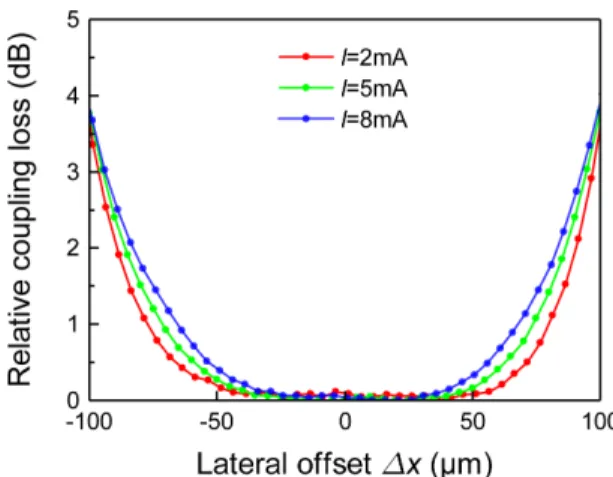
Figure 5 shows relative coupling loss of the ballpoint- pen connectors as a function of the lateral offset for different VCSEL driving currents under the center launching condi- tion. For all the driving currents, the relative coupling losses were well below 1.0 dB for lateral offsets of±50μm. How- ever, the lateral-offset dependence and the resulting toler- ance for the lateral offset changed with an increase in the driving current. This suggests that transmitted signal qual- ities are degraded through changing coupling loss by VC- SEL current modulation in actual optical systems with the ballpoint-pen interconnect.
To understand the driving-current dependent coupling losses, we measured near-field patterns (NFPs) of colli- mated output beams through the ballpoint-pen connector, as shown in Fig. 6 (a). The results showed that the colli- mated beams expanded more for higher driving currents.
The estimated beam diameters (four times the second-order intensity moments) were∼80μm, ∼100μm, and∼108μm for driving currents of 2 mA, 5 mA, and 8 mA, respec- tively. Note that the lateral-misalignment tolerances of the ballpoint-pen interconnect correspond to differences be- tween the collimated beam diameters and the imaginary
Fig. 5 Relative coupling loss of the coupled GI POFs with the ballpoint- pen interconnect under the center launching conditions as a function of the lateral offset for driving currents of 2 mA, 5 mA, and 8 mA.
Fig. 6 NFPs (top) and FFPs (bottom) of collimated output beams from the GI POF through the ballpoint-pen connector for the center launchings.
The driving currents were (a) 2 mA, (b) 5 mA, and (c) 8 mA. The scale bars are 100μm (top) and 10◦(bottom).
GI POF core diameter of ∼210μm, which was obtained from the NA of the output GI POF and the EFL of the ball lens[17]. The lateral-offset dependence of the cou- pling loss is related to the NFP whose electric-field distribu- tion is given by a Fourier transform of that for the GI POF without the ball lens. Therefore, larger collimated beams have higher spatial frequencies corresponding to higher- order guided modes in the GI POF.
Figure 6 (bottom) shows the corresponding far-field patterns (FFPs) of the collimated beams. The collimated beam divergences increased with driving current whereas the collimated beam diameters at the beam waist increased by the higher-order launched modes. The divergence angles (four times the second-order intensity moments) were∼4.2◦,
∼4.5◦, and ∼5.0◦ for driving currents of 2 mA, 5 mA, and 8 mA, respectively. These wider divergence angles for the higher driving current were attributed to higher-order guided mode launching with larger M2values, which were 5.4, 7.3, and 8.7 for driving currents of 2 mA, 5 mA, and 8 mA, re- spectively[18].
Fig. 7 Relative coupling loss of the coupled GI POFs with the ballpoint- pen interconnect as a function of the lateral offset for the radial launching offsets of 0μm, 10μm, and 20μm. The driving current was 2 mA.
Fig. 8 NFPs (top) and FFPs (bottom) of collimated output beams from the GI POF through the ballpoint-pen connector for a driving current of 2 mA. The radial launching offsets were (a) 0μm, (b) 10μm, and (c) 20μm.
The scale bars are 100μm (top) and 10◦(bottom).
3.2 Launching-Offset Dependence of Coupling Loss The influence of the launching-beam-position change on the coupling characteristics of the ballpoint-pen interconnect was evaluated. Figure 7 shows relative coupling loss as a function of the lateral offset for different launching beam positions. The driving current of the VCSEL was 2 mA.
The offset launchings significantly changed the connector- lateral-offset dependence of the coupling loss from the cen- ter launching.
Figure 8 shows the NFPs (top) and the FFPs (bot- tom) of the collimated beams for the launching beam po- sitions. For the radial launching offset of 10μm, the beam diameter, the divergence angle, and the M2 value of the collimated beam were ∼108μm, ∼5.0◦, and 9.0, respec- tively. By increasing the radial launching offset to 20μm, the beam diameter, the divergence angle, and the M2value were increased to∼136μm, ∼7.7◦, and 17.0, respectively.
For larger radial launching offsets, higher-order principal
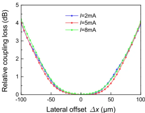
Fig. 9 Relative coupling loss of the coupled GI POFs with the ballpoint- pen interconnect as a function of the lateral offset for driving currents of 2 mA, 5 mA, and 8 mA. The radial launching offset was 20μm.
Fig. 10 NFPs (top) and FFPs (bottom) of collimated output beams from the GI POF through the ballpoint-pen connector for the radial launching offset of 20μm. The driving currents were (a) 2 mA, (b) 5 mA, and (c) 8 mA. The scale bars are 100μm (top) and 10◦(bottom).
mode groups (PMGs) with more guided modes could be selectively launched[19]. This resulted in the collimated beams having more expanded and speckled beam patterns, as shown in Fig. 8 (top). This was reflected in the de- graded beam qualities due to higher spatial frequencies of the launched modes by increasing the radial launching off- set. For a radial launching offset of 20μm, the coupling loss of the ballpoint-pen interconnect barely depended on the driving current, as shown in Fig. 9. Moreover, the cou- pling losses were kept below 1 dB for the lateral offsets of
±50μm whereas they were increased compared to those for the center launching. Figure 10 shows the corresponding NFPs (top) and the FFPs (bottom) of the collimated beams for the different driving currents. The driving-current depen- dence of the collimated beam characteristics was decreased from the center launching. For driving currents of 5 mA and 8 mA, the collimated beams had similar beam diame- ters of∼156μm, divergence angles of∼7.8◦, and M2values of 20.0. These values were also comparable to those for
timode VCSEL was investigated. For center launching, the lateral-misalignment dependence of the coupling loss was increased with an increase in the driving current, on which the transverse oscillation mode of the VCSEL depended.
This was attributed to higher-order launched modes and thus more expanded output beam of the GI POF with the ballpoint-pen connector. Using launching with a radial off- set of 20μm, the coupling losses below 1 dB for the lat- eral misalignments of ±50μm could be obtained with lit- tle driving-current dependence. This suggests that the data transmission quality for misaligned connection of the GI POFs can be improved further by optimizing launching sys- tems for the ballpoint-pen interconnects.
Acknowledgments
This paper is based on results obtained from a project com- missioned by the New Energy and Industrial Technology Development Organization (NEDO). We thank for provid- ing ballpoint-pen connectors and fruitful discussions with A. Mitsui and H. Suzuki of Mitsubishi Pencil Co., Ltd..
References
[1] K. Motohashi, “Media, culture and industry in the 4K/8K smart TV era,” New Breeze, vol.26, no.2, pp.5–7, April 2014.
[2] INTERFACE FOR UHDTV PRODUCTION SYSTEMS, ARIB ISTD-B58 Version 1.0, 2014.
[3] Y. Koike, Fundamentals of plastic optical fibers, Wiley, New York, 2015.
[4] Y. Koike and A. Inoue, “High-speed graded-index plastic optical fibers and their simple interconnects for 4K/8K video transmission,”
J. Lightw. Technol., vol.34, no.6, pp.1551–1555, March 2016.
[5] Graded-refractive-index optical plastic material and method for its production, by Y. Koike and M. Naritomi. (1994). JP Patent 3719733, US Patent 5783636, EU Patent 0710855, KR Patent 375581, CN Patent L951903152, TW Patent 090942, originally filed in 1994.
[6] Y. Koike and T. Ishigure, “High bandwidth plastic optical fiber for fiber to the display,” J. Lightw. Technol., vol.24, no.12, pp.4541–4553, Dec. 2006.
[7] A. Polley and S.E. Ralph, “40 Gbps links using plastic optical fiber,”
Proc. Opt. Fiber Commun. Conf. 2007, OMR5, Anaheim, USA, March 2007.
[8] S.R. Nuccio, L. Christen, X. Wu, S. Khaleghi, O. Yilmaz, A.E.
Willner, and Y. Koike, “Transmission of 40 Gb/s of DPSK and OOK at 1.55μm through 100 m of plastic optical fiber,” Proc. 34th Euro- pean Conf. on Opt. Commun., Brussels, Belgium, We.2.A.4, Sept.
2008.
[9] A. Inoue, T. Sassa, K. Makino, A. Kondo, and Y. Koike, “Intrinsic transmission bandwidths of graded-index plastic optical fiber,” Opt.
vol.22, no.6, pp.6562–6568, March 2014.
[13] T. Torikai, T. Yamauchi, S. Mine, N. Moriya, A. Mitsui, H. Suzuki, Y. Watanabe, M. Kanou, H. Takizuka, T. Toma, and Y. Koike, “Opti- cal I/O connectors employing ball-point pen type optical collimator lenses suitable for plastic optical fiber communications,” Proc. 21st Int. Conf. Plastic Optical Fibers, pp.227–231, Atlanta, USA, Sept.
2012.
[14] H. Takizuka, T. Torikai, A. Mitsui, H. Suzuki, Y. Watanabe, T. Toma, and Y. Koike, “A proposal of novel optical interface to transmit 8K- UHDTV for consumer applications,” Proc. 18th Microoptics Conf., pp.1–2, Tokyo, Japan, Oct. 2013.
[15] T. Toma, H. Takizuka, T. Torikai, H. Suzuki, T. Ogi, and Y. Koike,
“Development of a household high-definition video transmission system based on ballpoint-pen technology,” Synthesiology, vol.7, no.2, pp.118–128, May 2014.
[16] P.A. B´elanger, “Beam propagation and theABCD ray matrices,”
Opt. Lett., vol.16, no.4, pp.196–198, Feb. 1991.
[17] A. Nicia, “Lens coupling in fiber-optic devices: efficiency limits,”
Appl. Opt., vol.20, no.18, pp.3136–3145, Sept. 1981.
[18] H. Yoda, P. Polynkin, and M. Mansuripur, “Beam quality factor of higher order modes in a step-index fiber,” J. Lightw. Technol., vol.24, no.3, pp.1350–1355, March 2006.
[19] R.E. Freund, C.-A. Bunge, N.N. Ledentsov, D. Molin, and Ch.
Caspar, “High-Speed Transmission in Multimode Fibers,” J. Lightw.
Technol., vol.28, no.4, pp.569–586, Feb. 2010.
Azusa Inoue obtained an M.S. degree in electrical engineering from Keio University, Yokohama, Japan, in 2004, and a Ph.D. in inte- grated design engineering from Keio University, Yokohama, Japan, in 2008. In 2008–2010, he worked as a postdoctoral fellow in Kyushu Uni- versity, Fukuoka, Japan, where he worked on electro-optic polymer modulators. He worked as Project Assistant Professor in Keio University from 2010 to 2014. He has worked as Project Senior Assistant Professor since 2014. His cur- rent research interests include analyses, design, and control of microscopic polymer heterogeneities in low-noise GI POF materials for VCSEL-based MMF links with various modulation formats.
and Technology Award of the Society of Plastics Engineers, the Fujihara Award, the honor of the Medal with Purple Ribbon in Palace, and SID Spe- cial Recognition Award.