TM-U295
Installation Manual (English)
設置マニュアル (Japanese)
All rights reserved. No part of this publication may be reproduced, stored in a retrieval system, or transmitted in any form or by any means, electronic, mechanical, photocopying, recording, or otherwise, without the prior written permission of Seiko Epson Corporation. No patent liability is assumed with respect to the use of the information contained herein. While every precaution has been taken in the preparation of this book, Seiko Epson Corporation assumes no responsibility for errors or omissions. Neither is any liability assumed for damages resulting from the use of the information contained herein.
Neither Seiko Epson Corporation nor its affiliates shall be liable to the purchaser of this product or third parties for damages, losses, costs, or expenses incurred by purchaser or third parties as a result of: accident, misuse, or abuse of this product or unauthorized modifications, repairs, or alterations to this product, or (excluding the U.S.) failure to strictly comply with Seiko Epson Corporation’s operating and maintenance instructions.
Seiko Epson Corporation shall not be liable against any damages or problems arising from the use of any options or any consumable products other than those designated as Original Epson Products or Epson Approved Products by Seiko Epson Corporation.
Epson and ESC/POS are registered trademarks of Seiko Epson Corporation.
NOTICE: The contents of this manual are subject to change without notice.
© 1997 by Seiko Epson Corporation, Nagano, Japan.
EMC and Safety Standards Applied
Product Name: TM-U295Model Name: M66SA/M117A
The following standards are applied only to the printers that are so labeled. (EMC is tested using the Epson power supplies.)
Europe: CE marking Safety: EN 60950
North America: EMI: FCC/ICES-003 Class A Safety: UL 1950/CSA C22.2 No. 950 Japan: EMC: VCCI Class A
Oceania: EMC: AS/NZS 3548/ CISPR22 Class B
WARNING
The connection of a non-shielded printer interface cable to this printer will invalidate the EMC standards of this device. You are cautioned that changes or modifications not expressly approved by SEIKO EPSON Corporation could void your authority to operate the equipment.
CE Marking
The printer conforms to the following Directives and Norms:
Directive 89/336/EEC EN 55022 Class B EN 55024 IEC 61000-4-2 IEC 61000-4-3 IEC 61000-4-4 IEC 61000-4-5 IEC 61000-4-6 IEC 61000-4-11 Directive 90/384/EEC EN 45501 FCC Compliance Statement For American Users
This equipment has been tested and found to comply with the limits for a Class A digital device, pursuant to Part 15 of the FCC Rules. These limits are designed to provide reasonable protection against harmful interference when the equipment is operated in a commercial environment.
This equipment generates, uses, and can radiate radio frequency energy and, if not installed and used in accordance with the instruction manual, may cause harmful interference to radio communications. Operation of this equipment in a residential area is likely to cause harmful interference, in which case the user will be required to correct the interference at his own expense.
FOR CANADIAN USERS
This Class A digital apparatus complies with Canadian ICES-003.
Cet appareil numérique de la classe A est conforme à la norme NMB-003 du Canada.
Important Safety Information
This section presents important information intended to ensure safe and effective use of this product. Read this section carefully and store it in an accessible location.
Key to Symbols
The symbols in this manual are identified by their level of importance, as defined below. Read the following carefully before handling the product.
WARNING:
Warnings must be followed carefully to avoid serious bodily injury.
CAUTION:
Cautions must be observed to avoid minor injury to yourself or damage to your equipment.
Safety Precautions
This section presents important information intended to ensure safe and effective use of this product. Read this section carefully and store it in an accessible location.
WARNING:
Shut down your equipment immediately if it produces smoke, a strange odor, or unusual noise. Continued use may lead to fire. Immediately unplug the equipment and contact your dealer or a Seiko Epson service center for advice.
Never attempt to repair this product yourself. Improper repair work can be dangerous.
Never disassemble or modify this product. Tampering with this product may result in injury or fire.
Be sure to use the specified power source. Connection to an improper power source may cause fire.
Do not allow foreign matter to fall into the equipment. Penetration by foreign objects may lead to fire.
If water or other liquid spills into this equipment, unplug the power cord immediately, and then contact your dealer or a Seiko Epson service center for advice. Continued usage may lead to fire.
CAUTION:
Do not connect cables in ways other than those mentioned in this manual. Different connections may cause equipment damage and burning.
Be sure to set this equipment on a firm, stable, horizontal surface. The product may break or cause injury if it falls.
Do not use in locations subject to high humidity or dust levels. Excessive humidity and dust may cause equipment damage or fire.
Do not place heavy objects on top of this product. Never stand or lean on this product. Equipment may fall or collapse, causing breakage and possible injury.
To ensure safety, unplug this product before leaving it unused for an extended period.
Before moving the product, unplug it and unplug all cables connected to it.
Purpose of This Manual
This manual provides information to operators of the TM-U295 printer to describe basic operations to enable safe and correct use of the printer.
Notes on Usage
❏ Use specified paper.❏ Do not use solvents based on alcohol, benzine, thinner, or ketone to remove the dirt on the printer.
❏ If you ever transport the printer or store it for a prolonged period of time, attach the transportation damper.
Unpacking
When you unpack the TM-U295 printer, make sure you have these items.
If any item is missing or damaged, contact your dealer for assistance.
Note:
See the Note on page 7 for information about the screws. Damper
Ribbon cassette
Printer Parts
Control Panel
The control panel has three buttons and three indicators (LEDs).
Buttons
All three of these buttons can be disabled or enabled by the ESC c 5 command.
FORWARD
Feeds the paper forward based on the line feed amount set by ESC 2 and ESC 3.
REVERSE
Feeds the paper backward based on the line feed amount set by ESC 2 and ESC 3.
RELEASE
Pressing this button moves the rollers so that paper can be inserted or removed. (This state is called the “paper release mode.”)
Note:
Pressing the POWER switch while holding down the RELEASE button runs a self test. See “RunningaSelf Test.”
upper case printer cover document table POWER switch control panel DIP switch interface connector FG power connector
Indicators (LEDs)
POWER
This LED is on whenever power is supplied to the printer.
RELEASE
This LED is on when the printer is in the paper release mode and it is off when the printer is in the clamp mode. Paper can be inserted only when the printer is in the paper release mode.
This LED flashes to indicate an error condition in the following cases:
❏ Paper jam
❏ Home position error ❏ Timing error
❏ Drive circuit error
❏ Power supply voltage error
If this LED flashes, turn off the printer, make sure that no paper is jammed in it, and then turn it back on. If the LED is still flashing, contact your administrator or a qualified service person.
PAPER OUT
This LED is on when paper is not inserted or is not inserted correctly.
Removing the Transportation Damper
The printer is protected during shipping by a transportation damper that must be removed before you turn on the printer.
Pull the damper out and remove the strip of tape from the top of the printer, as shown below.
Attaching the Transportation Damper
If you ever ship or store your printer, prepare it by performing these steps:
1. Make sure that the printer is turned on. 2. Press the RELEASE button.
3. Press the FORWARD button. 4. Turn off the printer.
5. Put the transportation damper back where it was when you received the printer.
Connecting the Printer to the Computer
You need an appropriate serial interface cable to connect your computer to the printer.
1. Make sure that the printer and the computer are turned off.
2. Plug the serial interface cable into the interface connector on the back of the printer, as shown.
3. Tighten the screws of the serial interface cable connector.
Note:
Your printer comes with inch-type hexagonal lock screws installed. If you plan to use an interface cable that requires millimeter-type lock screws, replace the inch-type screws with the enclosed millimeter-type screws by using a hex screwdriver (5 mm). To distinguish the two types of screws, see the illustration below; the screw on the right is the millimeter type.
4. Connect the other end of the cable to the connector on your computer.
Notch (one or more lines)
Millimeter-type Inch-type
Grounding the Printer
You need an appropriate ground wire to ground your printer. Recommended wire is described below.
Wire thickness: AWG 18 or equivalent
Diameter of terminal to be attached to: 3.2 1. Make sure that the printer is turned off.
2. Tighten the ground wire in the position indicated as “FG” on the back of the printer with the FG screw, as shown.
Connecting the Power Supply
This printer requires an external power supply. Use an optional Epson power supply.
CAUTION:
Using an incorrect power supply can cause serious damage to the printer.
1. Make sure that the printer is turned off.
2. Plug the power supply’s DC cable connector into the printer’s connector as shown below. Note that the flat side of the DC cable connector faces up.
3. Plug the power plug of the power supply into an outlet.
Disconnecting the Power Supply
2. Unplug the power plug of the power supply from the outlet. 3. Hold the connector of the DC cable and unplug it from the
printer’s connector.
Installing the Ribbon
Be sure to use the EPSON ERC-27, the ribbon cassette that meets the printer’s specifications.
1. Turn on the printer.
2. Press the RELEASE button to turn on the LED. This puts the printer in the paper release mode.
3. Turn off the printer.
CAUTION:
4. Be sure to perform the steps above because it is necessary to make sure that the printer is in the paper release mode before you install the ribbon cassette.
5. Open the printer cover by slightly pressing the ridges on the top left and pulling the cover forward, as shown in the illustration below.
6. Check that the ribbon in the cassette is not creased or twisted. Then turn the feed knob in the direction of the arrow on the ribbon cassette to take up any slack in the ribbon.
7. Carefully insert the ribbon cassette in the printer as shown in the illustration below. Notice exactly where the ribbon must go.
8. Then push firmly on the right side and then the left side of the ribbon cartridge until each side clicks into place.
9. To put the cover back on the printer, first align the left and insert the tab on the top; then press the bottom until it clicks into place, as shown below.
Replacing a Used Ribbon
When your printing is not dark enough, it is time to replace the ribbon.
1. Follow steps 1 through 4 in the “Installing the Ribbon.” 2. Remove the used ribbon by grasping the handle and pulling
straight out, as shown by the arrow in the illustration below.
3. Follow the rest of the steps in “Installing the Ribbon.”
Inserting Paper
CAUTION:
Do not use wrinkled or curled paper.
Use paper that meets the printer’s specifications.
To insert paper, follow these steps:
1. Make sure that a ribbon cassette is installed in the printer. 2. Turn on the printer. The POWER LED comes on.
3. Press the RELEASE button. The RELEASE LED comes on, indicating that the printer is in the paper release mode. In this mode, the printer can accept paper and paper can be removed from it.
4. Insert the paper from either the front or the side, as shown in the illustration below. Insert the paper into the printer until it is stopped by the form stopper. The markings on the side of the printer can also be used to judge how far to insert paper.
5. Check the PAPER OUT LED. When you insert the paper correctly, the PAPER OUT LED goes out. If the PAPER OUT LED is still on, remove the paper and re-insert it.
Running a Self Test
Any time that you want to check the performance of your printer you can run a self test as described below. This shows whether your printer is working correctly. It is independent of any other equipment or software.
The self test checks the control circuits, printer mechanisms, print quality, RAM, ROM version, and DIP switch settings.
To perform a self test, follow the steps below:
1. Make sure that the ribbon cassette is installed correctly.
2. Turn on the printer and make sure the printer is in the released mode. If not, press the RELEASE button.
3. Insert a sheet of paper. Then turn off the power.
4. While holding down the RELEASE button, turn the power back on to start the self test.
5. To end the self test, turn off the power.
Setting the DIP Switches
You can change several interface settings by changing the DIP switch settings. If you need to change any of these settings, follow these steps:
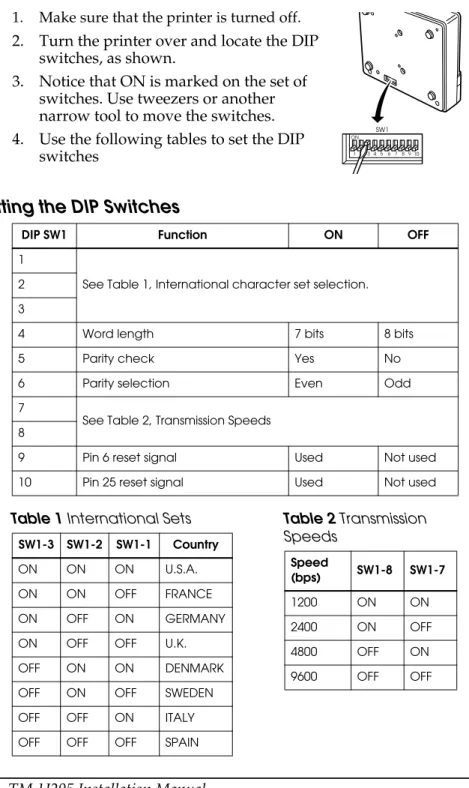
1. Make sure that the printer is turned off.
2. Turn the printer over and locate the DIP switches, as shown.
3. Notice that ON is marked on the set of switches. Use tweezers or another narrow tool to move the switches. 4. Use the following tables to set the DIP
switches
.
Setting the DIP Switches
DIP SW1 Function ON OFF
1
See Table 1, International character set selection. 2
3
4 Word length 7 bits 8 bits
5 Parity check Yes No
6 Parity selection Even Odd
7
See Table 2, Transmission Speeds 8
9 Pin 6 reset signal Used Not used
10 Pin 25 reset signal Used Not used
Table 1 International Sets SW1-3 SW1-2 SW1-1 Country
ON ON ON U.S.A.
ON ON OFF FRANCE
ON OFF ON GERMANY
ON OFF OFF U.K.
OFF ON ON DENMARK
OFF ON OFF SWEDEN
OFF OFF ON ITALY
OFF OFF OFF SPAIN
Table 2 Transmission Speeds Speed (bps) SW1-8 SW1-7 1200 ON ON 2400 ON OFF 4800 OFF ON 9600 OFF OFF
日本語日本語
TM-U295 設置マニュアル
© セイコーエプソン株式会社 1997 ご注意 (1) 本書の内容の一部または全部を無断で転載、複写、複製、改ざんすることは固くお断りします。 (2) 本書の内容については、予告なしに変更することがあります。 (3) 本書の内容については、万全を期して作成いたしましたが、万一ご不審な点や誤り、記載もれなど、お気づ きの点がありましたらご連絡ください。 (4) 運用した結果の影響については、上項にかかわらず責任を負いかねますのでご了承ください。 (5) 本製品がお客様により不適切に使用されたり、本書の内容に従わずに取り扱われたり、またはエプソンおよ びエプソン指定の者以外の第三者により修理・変更されたことなどに起因して生じた損害などにつきまして は、責任を負いかねますのでご了承ください。 (6) エプソン純正品およびエプソン品質認定品以外のオプションまたは消耗品を装着してトラブルが発生した場 合には、責任を負いかねますのでご了承ください。 EPSON© はセイコーエプソン株式会社の登録商標です。ご使用の前に
ご使用の際は、必ず「ユーザーズマニュアル」をよくお読みのうえ、正しくお使 いください。 「ユーザーズマニュアル」は、不明な点をいつでも解決できるように、すぐ取り出 して見られる場所に保管してください。安全にお使いいただくために
本書および製品には、製品を安全に正しくお使いいただき、お客様や他の人々へ の危害や財産への損害を未然に防止するために、以下の記号が使われています。 その意味は次のとおりです。内容をよく理解してから本文をお読みください。警告:
この表示を無視して誤った取扱をすると、人が死亡または重症を負う可能性が想 定される内容を示しています。注意:
この表示を無視して誤った取り扱いをすると、人が損傷を負う可能性が想定され る内容、および物的損害のみの発生が想定される内容を示しています。安全上のご注意
警告:
煙が出たり変な臭いや音がするなど、異常状態のまま使用しないでください。そ のまま使用すると、火災の原因となります。すぐに電源コードを抜いて、販売店 またはサービスセンターにご相談ください。 お客様による修理は危険ですから絶対におやめください。 分解や改造はしないでください。けがや火災の恐れがあります。 必ず指定されている電源をお使いください。他の電源を使うと、火災の恐れがあ ります。 本製品内部に異物を入れたり、落としたりしないでください。火災の恐れがあり ます。日本語 日本語 万一、水などの液体が内部に入った場合は、そのまま使用しないでください。火 災の原因となります。すぐに電源コードを抜き、販売店またはサービスセンター にご相談ください。
注意:
各種ケーブルは、本書で指示されている以外の配線はしないでください。誤った 配線をすると、故障や火災の恐れがあります。 不安定な場所(ぐらついた台の上や傾いた所など)に置かないでください。落ち たり、倒れたりして、けがをする恐れがあります。 湿気やほこりの多い場所に置かないでください。故障や火災の恐れがあります。 本製品の上に乗ったり、重いものを置いたりしないでください。倒れたり、壊れ たりしてけがをする恐れがあります。 本製品を長時間ご使用にならないときは、安全のため必ず電源コードを抜いてく ださい。本製品を移動する場合は、電源コードを抜いて、すべての配線を外した ことを確認してから行ってください。 プリンタに詰まった紙を取り除く場合、プリントヘッドには決して触れないでく ださい。プリントヘッドが低温になってから作業を始めてください。長時間印字 した後はプリントヘッドが高温になっているので、やけどなどの恐れがありま す。電波障害自主規制について
注意: この装置は、情報処理装置等電波障害自主規制協議会 (VCCI) の基準に基づくク ラス A 情報技術装置です。この装置を家庭環境で使用すると電波妨害を引き起 こすことがあります。この場合には、使用者が適切な対策を講ずるよう要求され ることがあります。本書の目的
本書は、製品を正しく安全にお使い頂くための基本的な製品取扱情報を、オペレー タに提供することを目的としています。取り扱い上のご注意
❏ 用紙は指定されたものを使用してください。 ❏ プリンタの汚れを除去する際は、アルコール、ベンジン、シンナー、ケトン系 溶剤は使用しないでください。プラスチックおよびゴム部分を変質、破損さ せる恐れがあります。 ❏ プリンタを輸送するとき、または長時間プリンタを使用しないときは、輸送用 ダンパーを取り付けてください。日本語日本語
同梱品
梱包箱には以下のものが入っています。万一損傷を受けているものがありました ら、お買い求め頂いたお店にお問い合わせください。 注記: ページの六角ロックネジに関する項を参照してください。各部の名称
輸送ダンパー リボンカセット 六角ロックネジ(2本) プリンタ 上ケース プリンタカバー ドキュメント台 POWERスイッチ コントロールパネル ディップスイッチ インタフェースコネクタ FG 電源コネクタ日本語 日本語
コントロールパネル
コントロールパネルには、3つのボタンと3つのインジケータ(LED)があります。ボタン
ESC c 5 コマンドで3つのボタンを有効または無効にすることができます。 FORWARD ESC 2 及び ESC 3 によって設定されている改行量に基づいて、順方向に紙送りを します。 REVERSE ESC 2 及び ESC 3 によって設定されている改行量に基づいて、逆方向に紙送りを します。 RELEASE 用紙の抜き差しができる状態(ペーパーレリーズ状態)にします。 注記: RELEASE ボタンを押しながら POWER スイッチを押すと、セルフテストが実 行されます。(「セルフテストの行い方」を参照してください。)インジケータ(LED)
POWER プリンタの POWER スイッチがオンの時、点灯します。 RELEASE ペーパーレリーズ状態のとき点灯し、用紙がクランプ状態(用紙がプリンタによっ て押さえられている状態)のとき消灯します。プリンタがペーパーレリーズモー ドのとき用紙を挿入することができます。 次の場合に点滅し、エラーを知らせます。 ❏ 紙詰まり ❏ ホームポジション検出異常 ❏ タイミング検出異常 ❏ 駆動回路異常 ❏ 電源電圧異常(電源投入時のみ)RRELEASE LED が点滅している場合は、プリンタの POWER スイッチをオフにし、 紙詰まりがないことを確認し、再度プリンタの POWER スイッチをオンにしてく ださい。それでもなお RELEASE LEDが点滅している場合は、管理者または保守担 当者にお問い合わせください。
PAPER OUT
日本語日本語
輸送用ダンパーの取り外し
輸送中、プリンタは輸送用ダンパーによって保護されています。プリンタを使用 する前に輸送用ダンパーを取り外してください。 イラストのように、プリンタのダンパーとテープを取り外します。輸送用ダンパーの取り付け
プリンタを輸送する時、または長期間プリンタを使用しない時は、以下の手順に 従ってダンパーを取り付けてください。 1.プリンタの POWER スイッチがオンであることを確認します。 2.RELEASE ボタンを押します。(RELEASE ボタンを押した状態を、ペーパーレ リーズ状態といいます。) 3.FORWARD ボタンを押します。 4.プリンタの POWER スイッチをオフにします。 5.ダンパーを取り付けます。コンピュータへのプリンタの接続
コンピュータとプリンタの接続には、プリンタの仕様に合ったインタフェース ケーブルをご用意ください。 1.プリンタとコンピュータの POWER スイッチがオフであることを確認します。 2.イラストのように、ケーブルのコネクタを、プリンタ背面のインタフェースコ ネクタに接続します。日本語 日本語 3.シリアルインタフェースケーブルのコネクタのネジを締め付けます。 注記: TM-U295 には、インチタイプの六角ロックネジが取り付けられています。接 続するインタフェースケーブルにミリメートルタイプのネジが付いている場合 は、TM-U295 に付いているインチタイプの六角ロックネジを外し、同梱され たミリメートルタイプの六角ロックネジを取り付けてください。六角ロックネジ の取り外し、取り付けには、5 ㎜の六角ドライバーを使用します。下の図は、六 角ロックネジの見分け方を示しています。 4.ケーブルのもう一方の端をコンピュータに接続します。
プリンタの接地
プリンタの接地には、プリンタの仕様に合ったアース線をご用意ください。以下 のアース線を使用されることをお奨めします。 アース線の太さ: AWG18 相当 接続するターミナルの直径:3.2 1.プリンタの POWER スイッチがオフになっていることを確認します。 2.アース線を、プリンタ背面の「FG」と示された場所に、備え付けのネジで締め 付けます。電源ユニットの接続
注意:
電源ユニットには、セイコーエプソン製電源(オプション)をご使用ください。 指定以外の電源を使うと、プリンタに重大な損害が発生する恐れがあります。 1.プリンタの POWER スイッチがオフになっていることを確認します。日本語日本語 2.イラストのように、電源ユニットの DC ケーブルコネクタをプリンタのコネク タに差し込みます。DC ケーブルコネクタの平らな面が上に向くようにしてく ださい。 3.電源ユニットの電源プラグをコンセントに差し込みます。
電源ユニットの取り外し
電源ユニットの取り外しは、以下の手順で行ってください。 1.プリンタの POWER スイッチをオフにします。 2.電源ユニットの電源プラグをコンセントから抜き取ります。 3.コネクタ部を持って、DC ケーブルコネクタをプリンタのコネクタから抜き取 ります。リボンカセットの取り付け
リボンカセットは、セイコーエプソン製リボンカセット ERC-27 のみをご使用く ださい。 1.プリンタの POWER スイッチをオンにします。 2.RELEASE ボタンを押します。LED が点灯し、プリンタがペーパーレリーズ状態 になります。 3.プリンタの POWER スイッチをオフにします。注意:
必ずこの手順に従い、プリンタをペーパーレリーズ状態にしてからリボンカセッ トを取り付けてください。ペーパーレリーズ状態でないと、リボンカセットを取 り付けることができません。日本語 日本語 4.イラストのように、プリンタ上面左側部分を軽く押しながらプリンタカバーを 手前に引き、取り外します。 5.カセットのリボンに、しわやねじれがないか確認します。リボンカセットのつ まみをリボンカセット上に示している矢印方向に回し、リボンのたるみを取り ます。 6.イラストのように、リボンカセットをプリンタの正しい位置に挿入します。 7.リボンカセットの右側、次に左側をカチッと音がするまで押し込みます。 8.プリンタカバーをプリンタの上に戻し、まず左側を合わせた後、カバー上面の タブを挿入します。次にイラストのように、プリンタカバーの下部をカチッと 音がするまで押し込みます。
リボンカセットの交換
リボンカセットのインクが薄くなったら、以下の手順で新しいリボンカセットに 交換してください。 1.「リボンカセットの取り付け」の1∼4の手順に従います。日本語日本語 2.使用済みのリボンカセットのハンドルを持ち、イラストの矢印方向に取り外し ます。 3.「リボンカセットの取り付け」の5∼8の手順に従います。
用紙の挿入
注意:
しわのある用紙や丸まった用紙を使用しないでください。 プリンタの仕様に合った用紙をご使用ください。 以下の手順に従って用紙を挿入してください。 1.リボンカセットがプリンタに取り付けられていることを確認します。 2.プリンタの POWER スイッチをオンにします。POWER LED が点灯します。 3.RELEASE ボタンを押します。RELEASE LED が点灯し、プリンタがペーパーレリーズ状態になり、用紙の抜き差しが可能になります。
4.イラストのように、プリンタの前方、または横方向から用紙を挿入します。用 紙は、ストッパに当たって止まるまで挿入してください。プリンタ側面のマー クを利用して、用紙をどこまで挿入するかを判断することもできます。
5.PAPER OUT LED を確認します。用紙が正しく挿入された場合、PAPER OUT LED が消灯します。PAPER OUT LED が点灯している場合は、用紙を挿入し直 してください。
日本語 日本語
セルフテストの行い方
プリンタのパフォーマンスをチェックしたいとき、以下のようにして、いつでも セルフテストを行うことができます。セルフテストでは、他の機器やソフトに左 右されることなく、プリンタが正しく機能しているかどうかを確認できます。 セルフテストでは、コントロール回路、プリンタ機構、印刷品質、RAM・ROM のバージョン、ディップスイッチ設定をチェックすることが可能です。 以下の手順に従ってセルフテストを実施してください。 1.リボンカセットが正しく取り付けられていることを確認します。 2.プリンタの POWER スイッチをオンにし、プリンタがレリーズ状態になってい ることを確認します。レリーズ状態でない場合は、RELEASE ボタンを押しま す。 3.用紙を挿入し、POWER スイッチをオフにします。 4.RELEASE ボタンを押しながら POWER スイッチをオンにすると、セルフテスト が開始されます。 5.セルフテストを終了するには、POWER スイッチをオフにします。ディップスイッチの設定
ディップスイッチの設定を変えることにより、インタフェースの設定を変えるこ とができます。必要に応じ、以下の手順に従って設定を変えてください。 1.プリンタの POWER スイッチがオフになっているのを確認します。 2.プリンタを裏返し、ディップスイッチがイラストの位置にくるようにします。 3.ディップスイッチの上には「ON」が記されています。ドライバーなど先端の 細い工具を使用して、ディップスイッチを動かします。 4.次の表をもとに、ディップスイッチを設定します。日本語日本語
ディップスイッチの設定
別表 1 国際キャラクタセット 別表 2 ボーレートの選択 ディップスイッチ 機 能 ON OFF 1 国際キャラクタセット選択 (別表 1 参照) 2 3 4 ビット長 7ビット長 8ビット長 5 パリティチェック パリティあり パリティなし 6 パリティ選択 偶数パリティ 奇数パリティ 7 ボーレートの選択 (別表 2 参照) 8 9 #6 ピンリセット信号 使用する 使用しない 10 #25 ピンリセット信 号 使用する 使用しないCountry DIP SW1-3 DIP SW1-2 DIP SW1-1
アメリカ合衆国 ON ON ON フランス ON ON OFF ドイツ ON OFF ON イギリス ON OFF OFF デンマーク OFF ON ON スウェーデン OFF ON OFF イタリア OFF OFF ON
スペイン OFF OFF OFF
転送速度 [bps] DIP SW1-8 DIP SW1-7
1200 ON ON
2400 ON OFF
4800 OFF ON
Printed on Recycled Paper Printed in China