1
Proceedings of 2018 ISFA 2018 International Symposium on Flexible Automation Kanazawa, Japan, 15 - 19 July, 2018
(IFSA2018-S077)
SURFACE TREATMENT AND TENSILE STRENGTH ANALYSIS OF FUSED FILAMENT
FABRICATION ADDITIVE MANUFACTURED PRODUCTS TREATED WITH THE ABRASIVE
BLASTING TECHNIQUE
Gustavo Quadra Vieira dos Santos Saitama University Sakura-ku, Shimookubo,255 Saitama City,Saitama, 338-8570 quadra.v.d.559@ms-saitama.u-ac.jp Jun`ichi Kaneko Saitama University Sakura-ku, Shimookubo,255
Saitama City, Saitama, 338-8570 jkaneko@mech.saitama-u.ac.jp Kenichiro Horio Saitama University Sakura-ku, Shimookubo,255 Saitama City, Saitama
338-8570 horiken@mech.saitama-u.ac.jp Takeyuki Abe Saitama University Sakura-ku, Shimookubo,255 SaitamaCity, Saitama, 338-8570 abe@mech.saitama-u.ac.jp Gustavo QUADRA VIEIRA DOS
SANTOS/Saitama University Jun`ichi KANEKO/Saitama University Kenichiro HORIO/Saitama University Takeyuki ABE/Saitama University
ABSTRACT
This research presents an examination of the Abrasive Blasting technique (Sandblasting) as an alternative for the surface treatment of Additive Manufacturing products obtained through Fused Filament Fabrication (FFF) method. The growing popularity of this kind of manufacturing brings more attention to its problems, and being the final product surface aspect, a known problem of this method, this research aims to find alternatives to the usual surface finishing techniques. The focus of this research then, was the surface quality of FFF products, and to analyze this quality, values of Surface Roughness (Ra) was used as a primary tool, being aided by microscopic pictures and F profiles from a profilometer. Another aspect of the research was the tensile strength analysis. It was considered important that this mechanical property was examined to understand the effects that the abrasive blasting treatment could bring to the additive manufactured products.
NOMENCLATURE 3D – Three Dimensional
ABS - Acrylonitrile butadiene styrene AM – Additive Manufacturing
ASTM – American Society for Testing and Materials FFF - Fused Filament Fabrication
PLA - Polylactic acid
Ra – Arithmetical mean roughness value
1.INTRODUCTION
This paper is consisted of different parts, the introduction that contains an explanation of the AM, and product finishing using a bibliographic background, the second part, which presents the materials and methods present in the research, the development, subdivided in 6 parts that are the steps of the research, and the conclusion.
The introduction of 3D printers in the industrial environment brought up a new kind of fabrication process that gathers increasingly more adepts, being new companies, home owners, as well as more traditional companies that already uses different kinds of product fabrication technologies. This process that has been gaining strength is nowadays nominated Additive Manufacturing, and despite being considered a new fabrication process, the estimates in relation to the use of it, in a near future are encouraging.
1.1 Additive Manufacturing
Although considered to be intuitive, a commonly used is found on the technical procedures manual of the ASTM (American Society for Testing and Materials) [1], defining it as being “a process of joining materials to make objects from 3D model data, usually layer upon layer, as opposed to subtractive manufacturing methodologies.”.
Currently some limitations are found in the Additive Manufacturing that could limit its advance, as some authors like [2] quotes, affirming that, the deficiencies in the process speed,
21
Proceedings of 2018 ISFA 2018 International Symposium on Flexible Automation Kanazawa, Japan, 15–19 July, 2018
2 in the surface finishing, in precision, and material property could disturb the fabrication process.
Although having some problems, like the ones quoted above [2] affirms that the use of the additive manufacturing to component building has grown over the past years, and despite previously having a prototype manufacturing focus, as time goes by, and with the improvement on this kind of process, the additive manufacturing products has been shown a great potential.
1.2 Product Finishing
As quoted before most of the complains and “defects” of the Fused Filament Fabrication 3D printing method lies within the surface aspect of the product, with a process of finishing being clearly required, to produce more visual appealing products, and with more appeal for the main public.
Product finishing as quoted by [3] is “the final machining operation performed to obtain a good quality surface integrity”. Different kinds of product finishing exist, and these methods can differ greatly from one another, having even chemical approaches and mechanical.
According to [4]” Sandblasting is a mechanical process consisting of driving a stream of abrasive material against a sample using a pressurized fluid, usually compressed air. The advantages of this technique are that it is suitable for mass production, it is fast and economical.”
2.MATERIALS AND METHODS
It was used on the research different equipment’s and material, to conduct the research, consisting of 3D printers (Tier Time UP Plus 2®), a sandblasting cabinet with a sandblasting gun (Anest Iwata- Campbell CHB 600®), a profilometer (Surfcorder ET 200®) a measurescope (Nikon MM 11®) and different sandblasting material (commonly referred as media) and for the tensile strength test, the IMADA MX 110™. The idea behind the abrasive blasting application is to remove the “layer marks” that are known to be inherent of the fused filament deposition 3D printing process, the media, small beads, hits the layers of material, and with the collision pressure, removes the excess of material, this idea is represented in the figure below.
Figure 1 – Sandblasting process Diagram Before the application of the Abrasive blasting, it was deemed necessary to perform another kind of surface finishing to serve as a benchmark to the current research. It was decided that the finishing with sandpaper would be a good alternative, since it is accessible, and does not need a specific training to perform the surface polishing.
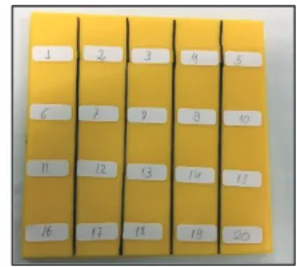
The samples used were parallelepipeds with 120mmx120mm of length and width and 5mm of height, had as printing settings 1 mm of pitch diameter, 0.2 mm of layer height and a diagonal pattern of material deposition.
The samples were divided in different “tiles”, of 20 mm x 34 mm that could be used for comparison in different times of
treatment application, and techniques. It was used ABS and Carbon Filament (15% carbon fibers and 85% PLA) as printing materials. Before the treatment started the surface roughness average (Ra) was measured, for all tiles, the procedure was to perform 10 measurements of different areas and use the average value as a comparison. The first sample printed is presented below:
Figure 2- ABS Filament Sample
Another step of this research was the tensile testing according to the tensile testing was performed following the directives of the ASTM D638, that sets the standards for the tensile testing for different materials, and in the case of the present research, plastic materials.
3.DEVELOPMENT
3.1 Sandpaper Operation (Comparison)
To perform the surface finishing it was chosen the tiles number 18, and 19, and the duration of the treatment was subject to the operator visual and tact senses, with that, the treatment had a 30 and 40 minutes respectively of duration with a number 500 sandpaper (granulometry). This technique managed to obtain a reduction from 46.54µm to 4.26µm for the tile 18 (90.9%), and from 46.897µm to 4.767µm for the tile 19 (89.8%).
Having the surface roughness reductions and timing required to obtain the results as a mean of comparison, the next step, the first operation of sandblasting was performed.
3.2 Investigation of Blasting Media (First Step) The parameters of the blasting operation were chosen due to equipment capability, research and trial and error. Being 0.4 MPa of pressure, sandblasting gun distance of 20 mm to 30 mm, angles of blasting within the range of 90º and 60º, and firstly 45 minutes of blasting, with the glass beads media, that ranges from 150µm -180 µm diameter, being considered a low abrasive media.
The results for the first round of treatment were not considered satisfactory, adopting the tile number 13 of the first sample to be blasted. The tile had a value of 48.13 µm of Ra and after the polishing, achieved an average value of 36.847 µm. It did manage to lower the Ra but not in a significant way, especially considering the time required to the treatment. With that, it was decided to change the media to gather different data and using the same sample.
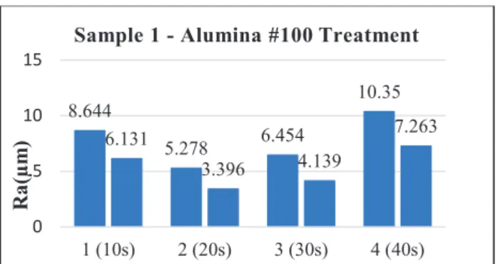
The parameters of blasting didn’t change, except for the blasting media, Alumina#100, with size of particles ranging from 106 µm to 125 µm, and the blasting period, that now had different timings, starting from low values, ranging from 10 to 120 seconds. The initial results were gathered in a graph and are presented below.
3 Figure 3 – Sample 1 Alumina #100 Treatment
This time the sandblasting with alumina presented satisfactory results, although the previous Ra`s were low, the percentage difference ranged from about 27% to 50%, the period of blasting was also considered a good point, as it was significantly lower than with the Sandpaper treatment. Since there was a variability found on the samples Ra, it is not possible to affirm what would be the optimum treatment time, since it could be different for each sample.
3.3 Different Blasting Angles Analysis
After the initial battery of testing it was decided to perform a different parameter change, this time the angle would be changed and the Ra`s differences would be compared. It was chosen as angles 30°, 45° and 60°. The 90° choice was not considered since it was considered a possible damaging source for the sample, due to its direct shock with the sample. The tests were performed in two steps, comparing, 30° with 60° and 60° with 45°, with tiles chosen by their Ra’s proximity. The sample had the same size parameters and material, ABS filament, as the sample 1. The figure bellow presents the percentage change for each angle, and the difference between the two angles.
Figure 4 – Alumina Sandblasting 60°, 30° comparison After analyzing the results showed above and more data gathered in the research it was concluded that between these three choices the 60° angle was the best choice for the sandblasting application in the above-mentioned conditions. 3.4 Carbon Filament Surface Treatment
The next step performed in the research was the abrasive blasting of a carbon filament printed sample, the blasting occurred with the same parameters as previously, with #100 alumina and an angle of 60°. The results were considered inefficient, since it raised the surface roughness values.
After the analysis of the results, that was deemed unsatisfactory, it was decided to perform another round with testing, this time with the Alumina #60, the idea for this change is that the larger diameter of the beads would bring a bigger denting, and with that a better result in the polishing procedure.
Figure 5 – Alumina (#60) - Carbon Filament The concept of changing the media proved to be correct, especially when considering the tile 2, that had a longer period of treatment. The process was considered effective since it had a considerable percentage change of Ra for the time spent. 3.5 Y axis Sample
Proceeding the research, it was printed samples, with both ABS filament and Carbon Filament, with a different printing orientation, (Y axis in a two-axis orientation) as shown below:
Figure 6 – Y axis printed Sample
The abrasive blasting was performed differently on the samples, the ABS one had an alumina#100 treatment and the Carbon Filament Sample Alumina #60. The results for the ABS sample are presented below:
Figure 9 – Sandblasting of ABS Y Axis Sample Like happened previously, the carbon filament samples presented similar results when compared to the ABS sample, both considered efficient for lowering the surface roughness.
3.6 Surface Primer Application 8.644 5.278 6.454 10.35 6.131 3.396 4.139 7.263 0 5 10 15 1 (10s) 2 (20s) 3 (30s) 4 (40s) Ra (µm )
Sample 1 - Alumina #100 Treatment
16.42 47.2 26.6 34.36 6.11 9.61 28.79 38.1 49.6857.42 0 50 100 30° 60° 30° 60° 30° 60° 30° 60° 30° 60° Pair 1 Pair 2 Pair 3 Pair 4 Pair 5
Ra
diff
er
ence
(%)
30°, 60° Percentage Difference Comparison
0 10 20 30
Before After Before After Before After Tile 3 (90s) Tile 6 (100s) Tile 2 (120s)
Ra
(µm
)
Carbon Filament Alumina #60 Treatment
16.84% 20.01% 39.95 % 13.946 9.478 13.279 7.391 14.645 7.407 0 2 4 6 8 10 12 14 16
Before After Before After Before After Tile 1 (30s) Tile 2 (60s) Tile 3 (90s)
Ra
(µm
)
ABS - Y Axis - Alumina #100 Treatment
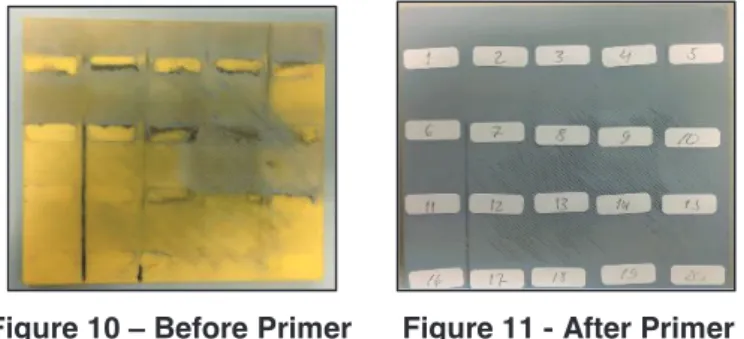
4 After the sandblasting operation it was observed that the surface of the sample had a “poor finishing” look, due to the presence of the microscopic beads in the sample, with this quality problem in mind, the application of a hobby spray Surface Primer, being this primer considered a cheap and easily accessible tool.
The idea behind the use of a surface primer, is that the coat of material can fill the gaps left by the “holes” made by the beads, and cover the material that were fixed in the samples, during the sandblasting application, pictures of before and post treatment with one layer of surface primer presented below:
Figure 10 – Before Primer Figure 11 - After Primer Not only the visual aspect was considered but also the surface roughness was analyzed, and the Ra results were assembled in a graph and are presented below:
Figure 12 – Roughness Comparison After primer Figure 12 also shows that the surface roughness had a significant lowering of its values, on the different kind of samples, tiles 1 and 2 suffered prior sandblasting treatment, 17 with the absence of surface treatment, and the tile 19 with prior sandpaper treatment. With both the visual aspects and surface roughness results in consideration it was considered an efficient way of improving the overall surface quality.
2.7 Tensile Testing
The last step of the research was to perform tensile testing, with the intention of measuring the ultimate tensile strength, for this part of the study the ASTM D638 was used as a standard, using the parameters for the samples and for the testing equipment. The sample model that was printed for the tensile testing is presented below:
Figure 13 – ASTM D638 Sample
In the first part, ABS samples were printed, and the tensile strengths were measured, in a later step, a sandblasting surface treatment was performed, and when comparing both results the difference was 10.37%. Due to variabilities concerning the Sandblasting, this step was remade, but this time a Mini CNC Router was adapted inside the sandblasting Cabinet, obtaining an average of 28.048 MPa for the tensile strength without treatment, and 24.925 MPa after treatment, which represents a negative change of 12.53%.
This change was not considered as a negative aspect of the sandblasting, since the change was considered small, and very similar to the manual operation of the sandblasting.
4. CONCLUSION
With the different steps of the research it was possible to assert that the Sandblasting treatment is an efficient alternative to lower the surface roughness of FFF 3D printed pieces, specially when considering the time required when comparison to other methods, and the lack of geometry limitations.
The surface presented some problems after the treatment, mainly poor visual aspect, but the coating with surface primer managed to improve the surface quality, not only considering the visual aspect, but also the surface roughness.
The Tensile Strength suffered small effect with the sandblasting application, it was considered that due to the small deformations produced by sandblasting the propagation of fractures was easier, but since the depth affected by sandblasting is considered small, the influence was not great, but further studies regarding the mechanical aspects of 3D printing materials, are encouraged.
REFERENCES
[1] American Society of Testing and Materials. “ASTM 52900: Additive manufacturing Technology Standards”. ASTM International, West Conshohocken, PA, 2015.
[2] MOYLAN, S., SLOTWINSKI, J., COOKE, A., JURRENS, K. and DONMEZ, A. M. “Proposal for a Standardized Test Artifact for Additive Manufacturing Machines and Processes”. National Institute of Standards and Technology. 2012.
[3] Jain, V.K., “Advanced Machining Processes”. Allied Publishers.2002.
[4] CAMATTARI, R., PATERNÒ, G., ROMAGNONI, M., BELLUCCI, V., MAZZOLARI, A. and GUIDI, V.. “Homogeneous self-standing curved monocrystals, obtained using sandblasting, to be used as manipulators of hard X-rays and charged particle beams”. Journal of Applied Crystallography, vol. 50. 2016
[5] American Society of Testing and Materials. “ASTM D638: Standard Test Method for Tensile Properties of Plastics”. ASTM International, West Conshohocken, PA, 2014 0
10 20 30 40
Before After Before After Before After Before After Tile 1 Tile 2 Tile 17 Tile 19
Ra
(µm
)
Primer Application ABS Sample
38.25% 25.62%
39.26%
37.7%