Interface for Barge-in Free Spoken Dialogue System Based on Sound Field Control and Microphone Array
4
0
0
全文
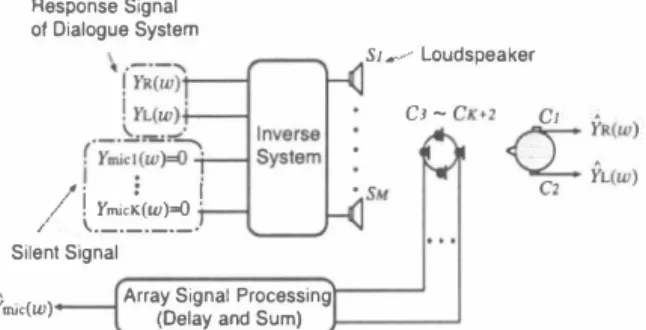
(2) Y(ω) [YR(ω), YL(ω), Ymic!(ω), ・・・, YmicK(ωW, (1) and the observed signals at e.u:h control point are repre sented by ナ(ω) = [九(ω), }i(ω), Ymic1 (ω),・" YmiCK(ωW, (2) where YR(ω) and YL(ω) are signals reproduced at the right and left ears of a user, respectively. The transfer function from the secondary sound source Sm to the control point Cn is denoted by Gnm(ω) where 1, 2, ・・・ , N, 1, 2, '" ,A1 and NくA1. Let G(ω) be an N A1 matrix consisting of Gnm(ω), and let be its A1 N inverse filter. Then, the relation between Y(ω) and Y(ω) is ex pressed as (3) Y(ω) G(ω)H(ω)Y(ω), where IN(ω) with IN(ω) denoting an N N identity matrix In Eq. (3), if the response sounds YR(ω) and h(ω) from the system are reproduced at both ears of the user, and if [Ymic1(ω),' • . ,YmicK(ω)] [0, ーー. , 0] is reproduced at each position of the microphone array elements, then the sound field can be realized without barge-in sound at e品ch of the microphone array elements, while the dialogue system gives the response sounds to the user. =. n. m. =. ニ. x. H(ω). x. =. G(ω)H(ω). x. =. =. 2.2.. Signal processing using microphone array. In Subsection 2. 1, sound field control is performed at each of K elements in the microphone array for acquisition of user's speech as a part of control points. In this subsec tion, we pay an attention to array signal processing. In this study, we adopt the delay-and-sum type for array signal processing. This is a general way for array signal process ing with small amounts of operations. The filter of k・th element in a delay- and-sum array is denoted by Wk (ω) for k 1, 2, ・", K. Then Wk(ω) can be expressed as =. Wk(W) ← =. 一. (め. where Tk stands for the arrival time difference of the tar get signal between a suitable array origin and k・th element position. Suppose that the signal added through the ar ray filters is a signal for the speech recognition. Then the eliminated barge-in sound in the speech recognition signal is expressed as K YmiC(ω) :L Wk (ω)九ick (ω) (5). stable because the output from each sound source is reduced to be minimum. Since the solution of an inverse matrix of G(ω) is not unique if the rank of is not reduced, the Moore Penrose type generalized inverse matrix is used as an inverse matrix which gives the least-norm solution. For this reason, the singular value decomposition of G(ω) is performed. U(ω) . [rN(ω), 0 rN(ω)三diag[μ!(ω), . . . , μN(ω)], (7) where U(ω) andV(ω) are N N and A1 A1 orthogonal ma trices, respectively μn(ω) for 1, 2,・・ ・,N are the singu and are arranged so that μn(ω)三μn+l(ω) lar values of in matrix rN(ω). ON,M-N(ω) denotes an N (A1 - N) null matrix. VH(ω) denotes the Hermitian transposed matrix ofV(ω). Then the Moore-Penrose type generalized inverse ma trix Gt (ω) ( of G(ω) is expressed as. H(ω). G(ω). =. x. G(ω). x. =. t. G (ω). When this delay-and-sum array is used, the system response sounds which come from other than the target direction are out of phase at each element, and only the user's speech which comes from the tむget direction is in phase at each element and added. In result, only the user's speech can be emphasized. 2ふInverse system design for sound field control. In a multi-point control system which controls plural control points by m叩y sound sources, a large amount of calculations and memories are needed to design an inverse filter in the time domain. Therefore, we design an inverse filter by using the least-norm solution (LNS) in the frequency domain [5]. The method has advantages that the amount of calculations are small, and the designed system is. H(ω). H(ω)). V(ω). ニ. [ fk)(ω) ] . UH(ω), o. (8). ,- ,..., � (9) AN(ω)三diag トh μN(ω) J1 l μ1(ω) μ2 (ω)h Therefore, the inverse filter can be designed by calcu lating an inverse matrix which gives the least-norm solution for every frequency.. H(ω). 2.4.. Barge-in sound elimination error when chang. ing the room transfer functions. The following arguments will be valid when the change of the transfer function is independent for every channel between loudspeaker and microphone. Suppose that the variation ムGnm(ω) caused by the change of room transfer functions is added to the original transfer function Gnm (ω). The elimination error of barge-in sound, ムYm吋ω) observed in Ymバω) , is then expressed as K .6. Ym (ω) :LWk(ω)i乞ムG (k+2)m(ω) ,. ic. M. =. (丸山. =. た=1. x. η=. Denoting the matrix norm of write Eq. (10) as. .6.Ymic(ω). H(ω) by I H(ω)11, we can , K. M. I H(ω)11. �. �:L :L.6.G(山)m(ω) (←μ料瓜H仲刷此 んLμバl(山いω仙 ) + H'm2凶2バ山(いω川 where 'm H n(ω) = Hmn(ω)/I H(ω)11. It is assumed that ムGnm(ω) is the Gaussian random variable with the vari ance (T2. Furthermore, since Hん(ω) is normalized by I H(ω)11, and is independent on the change of A1, the de viation in {-} of Eq. (11) can be expressed asげ耳石σ where ηis a suitable constant. Also, I H(ω)1 is propor tional to A1 because the followings hold in the case of 1/. =. 円〆臼 可I4 1ム.
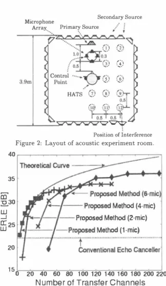
(3) μ1::::μN [4], IIH(ω) 11 = IIGt(ω) 11 = 1/1μN(ω) 1::::1/1μ1(ω) 1 = l/ IIG(ω)11α1/M. Therefore, the elimination error E(ω) of barge-in sound is expressed as E(ω) = �Ym吋ω) α 1/M.1/K.";耳石 1/v'M志. Secondary Source Microphone PrimarγSour四 Array' ' ・. 1. Control. 3.9mlλPoint. 、. '、.' ':‘ 、J. ::証 h汁ポ1 'Ç7�. Position of Interference. <w. Figure 2: Layout of acoustic experiment room.. 35. SIMULATIONS AND DISCUSSIONS. Experimental comparison of barge-in sound. elimination performance. The barge-in sound elimination performance of the pro posed method is evaluated through the simulations which are carried out by using the measured room impulse re sponses in order to investigate the robustness against the change of room transfer functions. For comparison, the per formance of the conventional acoustic echo canceller is also computed. In the experiment, the interference, i.e., a life size manikin is arranged near a user under the assumption that a person obtains access to the user so as to cause the change of the room transfer functions. In addition, since this experiment is interested in the robustness against the change of room transfer functions, the processing of elimi nating the barge-in sound is performed by using the filter coe伍cients before updating after the room transfer func tions change. The barge-in sound elimination performance is evaluated by using ERLE (Echo Return Loss Enhance ment) in Eq. (13) . ERLE=川oglO(乞 {Ymicr.f(ω) }2/乞{E(ω)} 2),. G). ・h・ も ぜ 戸,... """\. ..c ... 庁、 J. HATS. nu kd qu 内4 { 国立 凶」広凶. 3.1.. 、. /orι...&..0). (12). In other words, Eq. (12) shows that the elimination er ror of barge-in sound at the change of transfer functions is inversely proportional 旬、川イ• K. Thus, if the number of transfer channels from loudspeakers to microphones in creases, the proposed barge-in sound elimination method is more robust against the change of transfer functions. It is remarked that it is difficult in the real environment to prove whether or not the variation ムGnm(ω) caused by the change of room transfer functions is independent for every channel between loudspeaker and microphone. How ever, the simulation results using real environmental data described in the next section show that the error estimation computed using Eq. (12) is acceptable. 3.. ç�一千f. 20 15. ーート一一-Pro問sed Method (4-mìc). ・←I一一{- Proposed Method (2・mìc) f�'r一一 一-I Proposed Method (1-mic) """""" l -. o. 20. ' """'' ' ' ' ' ' "[,'�二iiムi. 40. 60. 80. iムiiiJiiLi. 100 120 140 160 180 200 220. Number 01 Trans1er Channels. Figure 3・ERLE for different number of the room transfer channels from loudspeakers to microphone array elements. a. Conventional acoustic echo canceller. In the experiment, an acoustic echo canceller with fixed filter coe白cients is constructed without using a specific adaptive algorithm in the echo canceller. The experiment is carried out under the assumption that when the transfer functions are in time-invariant, and the filter coefficients are estimated accurately.. (日). b. Proposed method. The inverse filter in the proposed method is ca1culated only using the impulse r田ponses in case there are no trans fer functions change. The inverse fì.lter are designed by the technique of using the least-norm solut問1 (LNS) [5]. The design conditions of the inverse filters are such as the num ber of secondary sound sources M = 4 to 36, the number of control points Nニ3 to 8, fi.lter length 32768, and passband range 150 to 4000 Hz. In Fig. 3, ERLE is shown forもhe number of transfer channels (= M. K) from loudspeaker to microphone. The theoretical curve in the figure is obtained by plotting the ERLE derived from Eq. (12), which is given by ERLE'h.叫 = 1010glO(乞 {九licref (ω) }2/乞{E(ω) }2 ). where Ymicr.f(ω) is the signal reproduced the sys七em re sponse sound at a standard microphone and E(ω) is the error signa1 in the barge-in sound elimination. The arrangement of the acoustic experiment room is shown in Fig. 2 where reverberation time is about 200 ms. The room impulse responses are measured in the experi ment room where the primary sound source is a loudspeaker used for a spoken dialogue system in the acoustic echo can celler. The room impulse responses are sampled with fre quency 48 kHz and the magnitudes are quantized to 16 bit. In the experiment, we use a circle array with 6 elements and one microphone to six microphones by our choice. As for the spoken dialogue system sounds, we use the sound from 6 men and 6 women, totally 12, through the ASJ database. ERLE is computed by the average value of the results from the above 12 people.. qd.
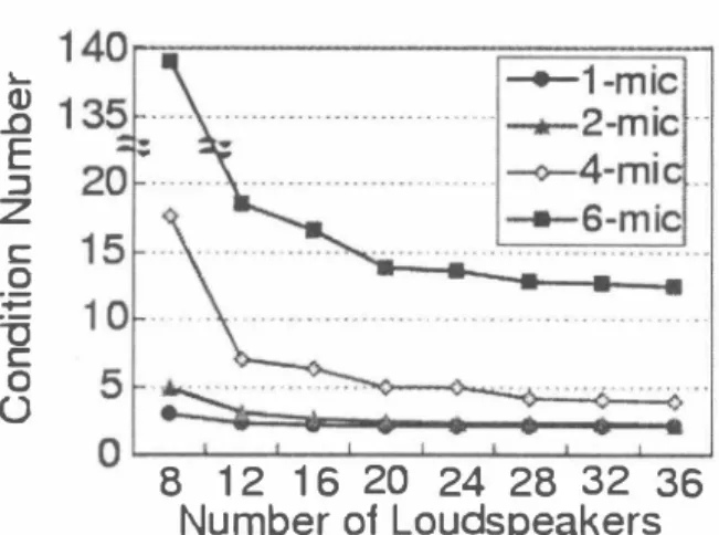
(4) 』ωDE コZ co一 戸一 万C00. 。. 8 12 16 20 24 28 32 36 Number 01 Loudspeakers. Figure 4: Cond.ition number of the average in passband. と+ 10 loglO{ 1/{I/(M. K)} ) と+ 10 loglO(M・ K), (14) where ç is a suitable constant. This figure shows that the barge-in sound elimination performance is improved if the number of transfer channels increases. It also turns out that the deviation between the experimental and theoretical values arises when the number of microphone array elements increases. The reasons are as follows: (1) The stability margin of the inverse filter becomes small when the number of control points is close to that of secondary sound sources. (2) When there exist too many transfer channels, the in dependency of each channel can not be assumed. con sequently, the performance is saturated. To prove the above claim (1), the condition number of a transfer function matrix G(ω), say cond(G), which repre sents the instability of an inverse filter, is shown in Fig. 4. This can be computed by the ratio between the maximum and minimum singular values, μ1 and μN, of matrix G(ω) as follows: cond(G) =μ1/μN・ (15) This figure shows that the condition number increases when the number of microphones (equal to the number of control points minus two) increases. In addition, such a tendency becomes remarkable when the number of secondary sound sources is smal!. This causes a large degradation of the ERLE value. For example, the numbers of channels are 32 and 48 for 4-mic and 6-mic, respectively. Comparing the conventional acoustic echo canceller and the MONI method (corresponding to l-mic case) with the proposed method in Fig. 3, it is seen that the proposed method is more robust against the change of transfer func tions if the number of transfer channels is increased. α. 3.2.. hble 1: Results of word accuracy [%] 11 l-mic 1 2-mic 1 4・mic 1 6-mic 1 I 12 loudspeakers 11 75.4 1 79.8 1 81.8 1 83.5 I 24 loudspeakers 11 79.8 1 83.2 1 85.0 1 86.0 36 loudspeakers 11 81.6 1 84.1 1 85.3 1 86.5 the speaker independ巴nt PTM made from clean speech. As user's speech, 200 sentences obtained from 23 male and fe male are usedもhrough the JNAS database and a sentence from a female speech is used through the ASJ database as a dialogue system response sound. Experimental conditions such as obstacle訂rangements are the same as in the pre vious one. In addition, the resultant recognition score is computed by the avera伊of the values from 200 persons totally. The results of re∞gnition experiment show that the word accuracy is -25.2% before signal processing and 51.3% by using the conventional echo canceller. Recognition re sults obtained by the proposed method are shown in Table 1. The recゅgnition results show that when changing the transfer functions, the degradation of speech recognition accuracy can be suppressed by increasing the number of transfer channels from loudspeaker to microphone. |. 4.. CONCLUSION. It has been shown that in the system with sound field control and microphone array, the performance to the change of room transfer functions is dependent on the num ber of transfer channels from loudspeaker to microphone and the stability of the inverse filter. The proposed method has shown the better performance than the conv哩ntional acoustic echo canceller. Moreover, by increasing the num ber of array elements, the number of loudspeakers to be required in MONI method has been reduced, and the inter face for a barge-in free spoken dialogue system has be屯ome more robust against the change of room transfer functions ACKNOWLEDGEMENTS. We would like to thank Dr. Shoji Makino for his de tailed discussions. REFERENCES [1] B.H. Juang and F.K. Soong, “Hands-free telecommu日ト cations," Proc. International Workshop on Hands-Free Speech Communication, pp.5-8, Kyoto, Japan, April 2001. [2] W. Herbordt and W. Kellermann,“Acoustic echo cancel lation embedded into the generalized sidelobe c印celler," Proc. European Signal Processing Conf. , vol.3,Tampere, Finland,September 2000. [3] Yang-Won Jung, JトHa Lee, Young-Cheol Park and Dae Hee Youn,“A new adaptive algorithm for stereophonic acoustic echo canceller, " Proc. International Conf. on Acoustics, Speech and Signal Processing, vol. 2 pp.801804, Istanbul,τ'urkey, June 2000. [4] K. Mino, Y. Tatekura, H. Saruwatari and K. Shikano, “Bargeトin free spoken dialog system using virtual sound field reproduction," IEICE Technical Report, EA2001・83,. Experiment of speech recognition. [5]. By using a large vocabulary recognition engine: Julius ver. 3.2 [6], the suppression effect of speech recognition ac curacy degradation by barge-in sound elimination is eval uated. Th巴 signal obtained by adding the barge争.寸in sound. 2001 (in Japanese). Y. Tatekura,H. Saruwatari and K. Shikano, "An iterative inverse filter design method for the multichannel sound field reproduction system," IEICEτ'rans. vol.84・A, no.4, pp.991-998, April 2001.. [6] A. Lee, T. Kawahara, and K. Shikano,“Julius-an open source real-time large vocabulary. e叫凶lirr凶I. Proc.. used for a rec∞ognition experiment. A phoneme model is. recognition. engine,". European Conf. on Speech Communication and. Technology, pp.1691ー1694,Aalborg, Denmark,Sept. 2001.. Aせ 11ム 唱'ム.
(5)
図
関連したドキュメント
All (4 × 4) rank one solutions of the Yang equation with rational vacuum curve with ordinary double point are gauge equivalent to the Cherednik solution.. The Cherednik and the
In the second computation, we use a fine equidistant grid within the isotropic borehole region and an optimal grid coarsening in the x direction in the outer, anisotropic,
In this section we briefly review certain basic known results concerning the num- ber K n of key comparisons required by Quicksort for a fixed number n of keys uni- formly
For arbitrary 1 < p < ∞ , but again in the starlike case, we obtain a global convergence proof for a particular analytical trial free boundary method for the
Here we continue this line of research and study a quasistatic frictionless contact problem for an electro-viscoelastic material, in the framework of the MTCM, when the foundation
Then it follows immediately from a suitable version of “Hensel’s Lemma” [cf., e.g., the argument of [4], Lemma 2.1] that S may be obtained, as the notation suggests, as the m A
discrete ill-posed problems, Krylov projection methods, Tikhonov regularization, Lanczos bidiago- nalization, nonsymmetric Lanczos process, Arnoldi algorithm, discrepancy
[Mag3] , Painlev´ e-type differential equations for the recurrence coefficients of semi- classical orthogonal polynomials, J. Zaslavsky , Asymptotic expansions of ratios of
