ISSN -0258-2724
西 南 交 通 大 学 学 报
2018 年 6 月 DOI: 10. 3969/j.
issn. 0258-2724.2018.05
JOURNAL OF SOUTHWEST JIAOTONG
UNIVERSITY
Vol.53 No.5 October 2018
Category.
Environmental Sciences
E
LECTRO
-F
LOTATION AS THE
M
ETHOD OF THE
W
ATER
T
REATMENT IN
R
ECYCLING
P
ROCESS OF
C
ONTAMINATED
W
ATER
AS AN
I
NTEGRAL
P
ART OF THE
R
EVERSE
L
OGISTICS
S
YSTEM
Anna Antonyováa,*, Peter Antonyb
a Faculty of Management, University of Prešov in Prešov
Konštantínova 16, 08001 Prešov, Slovak Republic, e-mail: [email protected]
bAPmikro
Pavlovičovo Námestie 19, 08001 Prešov, Slovak Republic, e-mail: [email protected]
Abstract
Proper management of water is a challenge for every individual but especially for companies. Nowadays also legislation obliges companies to clean the wastewater before being discharged into municipal public sewer especially if they use some chemicals or oily elements in their production process. Construction of the wastewater cleaner depends directly on the way of pollution, the amount of contaminated water and the energy demand of the cleaning process. The paper deals with the construction of the wastewater cleaner, which is based on the technology of electro-flotation for the treatment of water contaminated with the disperse colorants. The experimental work as well as the modelling using the statistical methods proved the suitability of the chosen technology. Also, each color combination requires a specific time period for the water treatment. The authors determined the time interval for cleaning the wastewater that was polluted with yellow color to 33 minutes. Finally, the wastewater cleaner that is based on the electro-flotation technology was included in the company's reverse logistics system.
抽象 適當的水管理對每個人都是一個挑戰,尤其是對公司而言。如今,立法還要求公司在排放到市政 公共下水道之前清潔廢水,特別是如果他們在生產過程中使用某些化學品或油性元素。廢水清潔 劑的建造直接取決於污染方式,污染水量和清潔過程的能量需求。本文論述了廢水淨化器的建 設,該廢水淨化器基於電浮選技術處理被分散著色劑污染的水。實驗工作以及使用統計方法的建 模證明了所選技術的適用性。而且,每種顏色組合需要特定的水處理時間段。作者確定了將被黃 色污染的廢水清洗至33分鐘的時間間隔。最後,基於電浮選技術的廢水淨化器被納入公司的逆向 物流系統
Keywords: wastewater recovery, innovative treatment technologies, electro-flotation, reverse logistics system.
I. I
NTRODUCTIONWater, which is nowadays considered a strategic resource, is necessary not only for human wellbeing but also for the ecosystem as a whole. To maintain the environment in a good
condition requires the involvement of each individual as well as a company, especially through its reverse logistics system.
Water conservation awareness is so important factor in behaviour of each individual that it directly influences the water consumption in
households. The awareness can be increased especially through education and public campaigns. Two methods were used to survey the water consumption in households of chosen villages in China [4]: questionnaire and water-use diary. Finally, the water-use diary was proved as suitable observation method with accurate data. The data in questionnaire were considered as perceived consumption. Discrepancies in actual and perceived water consumption point to the need to increase water consumption awareness in specific activities, such as for instance: cleaning, personal hygiene, kitchen, etc.
There are still many places of drought, the very important question is what kind of water and how it should be used for agricultural purposes. The literature review [7] tries to stress the tendency to use the wastewater for irrigation purposes in agriculture. As every such tendency affects soil texture properties, it is very important to be aware of what conditions must be fulfilled for the water quality. Nowadays, especially microbiological risk is quantitatively evaluated.
The environmental ecosystem depends directly on the quality of water, but it also includes mechanisms for getting involved directly in the cleaning process. Building technologies, which are based on sustainability and recycling processes, is a crucial task for current research and development.
One of the ways how it is possible to make decision for a natural alternative to technical methods is through the direct involvement of the plants into the process. The natural alternative is for instance construction of wetlands for the purpose of wastewater treatment [21]. The method uses supply of oxygen in the root zone for direct degradation of pollutants as oxidation plays an important role in metabolism performed by microorganisms. Another material that is produced on natural base and is important for water remediation is biochar [15]. Biochar is produced from biomass and it is used also for carbon sequestration and soil remediation as well as its conditioning.
The relatively widespread contaminants are for instance heavy metals [3], especially: lead, mercury, cadmium, zinc, copper, nickel, cobalt, iron, manganese and chromium. Heavy metals occur mostly in the form of natural minerals such as for instance: silicates, carbonates, oxides and sulphides. Testing which substances are harmless and which are harmful to the human organism together with the development of effective technologies for environmental remedy is a crucial role.
Although legislation obliges companies working with chemical substances to ensure that wastewater was cleaned before being discharged into public sewers, some chemicals and, in particular, pharmaceuticals appear in municipal wastewater [8]. Therefore, full-scale municipal wastewater treatment plants must also focus on the removal of pharmaceuticals and some specific biologic pollution from wastewater. Pharmaceuticals and micro-pollutants [2] as endocrine disrupting compounds (EDC) may occur directly in effluents of a waste water treatment plant. Therefore the water pollution control is necessary to monitor the concentration, especially in the places with the aquatic environment. Bioreactor membrane (MBR) is often used for the treatment of wastewater with a higher incidence of pharmaceuticals [17]. Membrane, which is used during the water treatment through activated sludge process (ASP), is fouling quite often what means especially increasing maintenance costs [5]. Prediction with dependency on parameter of mixed liquor quality might set the optimum intervals to periodic application of chemicals to keep the membrane in the process.
Application of technologies such as disinfection, rapid sand filtration, flocculation and coagulation is important in conventional drinking water treatment processes [14]. However the efficiency of conventional technologies should be increased to remove organics such as oscillatorialimnetica and microcystin toxins from sources of drinking water, which appeared for instance in the Nile River in Egypt. Therefore, continuous monitoring of the quality of drinking water in treatment plants becomes a necessity.
Technology of anaerobic digestion [18] is used for treatment of industrial wastewater which is contaminated with high strength organic effluents. The anaerobic reactors were developed for instance for the digestion of selected organic effluents from slaughterhouse, paper and distillery pulp.
The occurrence of triclosan, which is widely used as an antimicrobial agent, subsequently occurs in the aquatic environment, lake sediments as well as surface waters [20]. Therefore it should be monitored also in wastewater treatment plants. The problem of possible reuse of the wastewater effluent in textile industry was illustrated through the technologies of ion exchange and chemical coagulation as well as electrochemical method [11]. To increase the efficiency of electrochemical method, a certain amount of hydrogen peroxide was added.
Dissemination of nitro-aromatic explosives into the environment [19], especially in the military as well as the stone mining industry, may also cost a serious problem. The treatment methods for the remediation of soil and water, which are contaminated this way, also require specific technologies.
Creating new technologies is sometimes linked to the detailed research of individual chemicals and their interactions, such as proton-relays involving a water molecule [16]. Computing organic stereo-selectivity is one of the specific methods that are also used in the field of chemistry.
Nano-filtration and ultrafiltration are considered to be modern efficient technologies for the surface water treatment [10]. A Swedish water treatment plant with a fully automated pilot is introduced. Nano-filter and coagulation were used before an ultrafilter for the treatment of row water. One of the advantages of the nano-filtration as well as ultranano-filtration technologies is that the used installed membranes require lower chemical consumption.
Use of iron oxide nanomaterials is a promising way in technologies for wastewater treatment [22]. However we can say that it is still in the early stage with respect to its possibilities in application. Iron oxide nanomaterials are usually applied as photo-catalysts and nano-sorbents. The technology is sometimes used only to increase the removal efficiency.
Another method for the water treatment is for instance photocatalytic ozonation [12] were various metal oxide semiconductors were tested to increase the technology efficiency.
The analytical methods using solid-phase extraction, which was followed by liquid chromatography-electrospray ionization tandem mass spectrometry, were used to test antimicrobials [13]. Finally thirty-one antimicrobials were investigated in the final effluents from eight wastewater treatment plants in Canada.
Hydro-cyclone is introduced as technology to remove oily substances from offshore water [9].
A set of electrochemical technologies [6] is used for the water treatment. Depending on the type of pollution and possible further use of water, the following technologies can be used: electro-oxidation, electrocoagulation (EC), electrodeposition and electro-flotation (EF). Flotation as the method was formerly used to obtain the valuable minerals from ores. Finally electro-flotation, together with the other electrochemical technologies is used for deposition of organic as well as inorganic
pollutants. In our presented research we will stress the place of electro-flotation among the treatment technologies with respect to its role and specification. Water treatment using the electro-flotation is included also into the recycling process as an integral part of the reverse logistics system and was tested on the wastewater contaminated with dispersed colorants. We will also follow our previous research [1] regarding testing the level of the water clarity for setting the optimum time for the cleaning process.
II. M
ATERIALS ANDM
ETHODS A. Electro-flotation as a processElectro-flotation, as one of electrochemical technologies, is based on the bubble creation. The bubble size directly influences the effectivity of the treatment process. The bubbles are created during the following electrolytic reaction:
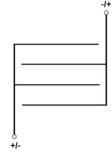
Oxidation at anode: 2𝐻2𝑂 → 𝑂2+ 4𝐻++ 4𝑒− (1) Reduction at cathode: 4H2O + 4e- → 2H2+ 4OH- (2) Overall reaction: 2𝐻2𝑂 → 2𝐻2+ 𝑂2 (3)
Figure 1 illustrates the meander shape of the electrode construction.
Figure 1.Shape of the electrode construction To make the electro-flotation process possible, oxidation agent should be present in the mixture. In our experimental work the acetic acid in concentration of 1% was used as oxidation agent. During the cleaning process the bubbles bind the particles of dirty water and carry them to the water level. Electro-flotation is mostly used to remedy the waste water contaminated with some
oil mixtures. Both bubble and dirt create concentrated foam on the water level. Figure 2 illustrates the electro-flotation process in details through the schematic representation.
Figure 2.Detailed description the system of the electro-flotation process through the schematic representation
The water that is during the production process contaminated with some oily elements is concentrated in the tank (1) with the pump to pour the water into the reservoir (2). The contaminated water is in the reservoir stirred with acetic acid as oxidation agent to allow electrolytic reaction. The acetic acid itself in concentration of 8% is stored in separate tank (3). The process of electro-floating itself takes also place in a separate container: the flotation tank (4). The polluted foam is wiped with the scraper (5) from the surface of the flotation tank. Other system components include, in particular, process control elements, such as the outlet valve (6) for pumping up the water to the flotation tank as well as outlet valve (10) for purified water from the flotation tank and check valve (9). Pump (7) for pumping the water into the flotation tank as well as pump (8) with the flow meter for the implementation of acetic acid into the contaminated water and pump (11) for pumping of the purified water from the flotation tank. Output filter (12) is checked against overfilling with overfill alarm (13). Flotation tank (14) is also checked against overfilling with signaling (15) of the dirty water level. Lower level (17) as well as upper level (16) of contaminated water in the tank is shown too.
Contaminated water that contains acetic acid is pumped (18) for mixing. The water in the vessels is controlled for its level through the following signaling: signaling (19) of filling up with acetic acid, signaling (20) of the minimum level of acetic acid, signaling (21) of overfilling the tank with contaminated water, sensor and signaling (22) of the upper level in the flotation tank, signaling for operation (23) of the flotator
and signaling (24) of passing an electric current through electrodes on the bottom in the flotation tank.
Finally, purified water is discharged through the outlet (25) into the municipal sewage system. B. Electro-flotation as included into the
company reverse logistics system
As legislation obliges companies to treat wastewater before being discharged into municipal sewers, companies are forced to include the process of cleaning water from chemical substances into their reverse logistics system. To solve the problem with wastewater that is contaminated with the disperse colorants; the wastewater cleaner was constructed for the company with the production of boxes for packaging purposes. The water is mostly dirty because of the decoration of the boxes as well as the result of cleaning the machines.
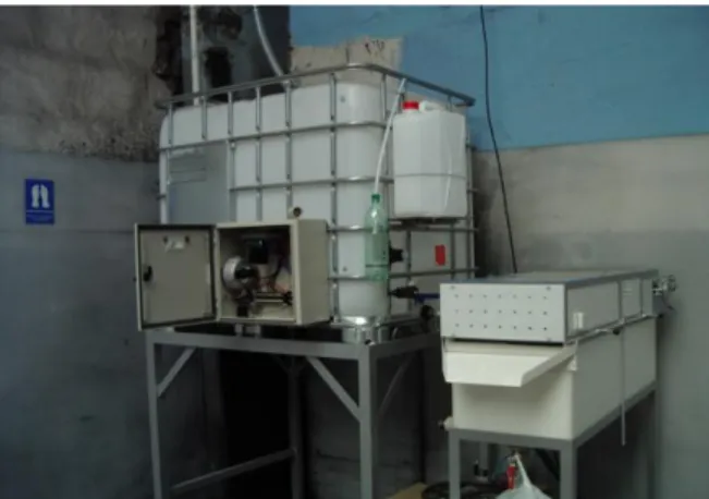
The equipment of the wastewater cleaner was built according to the principles, which are expressed in Figure 2 with the schematic representation. Figure 3 illustrates the whole equipment with its individual parts.
Figure 3.The equipment of the wastewater cleaner with its individual parts
Figure 4 shows the view on the equipment with the detail of the control box that is open. The control box also includes an integrated circuit for coordinating control elements to direct the water purification process.
Figure 4.View on the equipment of the wastewater cleaner with the detail of the control box that is open After wastewater has been cleaned, the dirty foam of high concentration is formed on the surface of the water. The foam, which is expressed in Figure 5, is collected and transported to another company for further processing while the cleaned water is of such quality that it can be discharged into municipal sewage.
Figure 5.Output of the foam that is collected and transported into another company for further processing C. Experimental laboratory work
In our research, modelling of the clarification processes of wastewater that was contaminated with the disperse colorants was performed. The level of the water clarity was tested during the treatment process. Figure 6 shows equipment for checking the level of the water clarity during the flotation process in the phase of the experimental work.
Figure 6.Equipment for checking the level of the water clarity during the flotation process
Testing the clarity level is very important as water should be discharged into municipal sewage in the phase of the highest cleanliness. The experimental device comprises flotator that is placed in the protective metal container (10). Stainless steel electrodes (3), which are expressed in Figure 7, with electrical current connection (11), enable the flotation process running. The dirty foam (5) accumulates on the top of the flotator.
As water cannot be tested directly in the flotation tank, it is monitored in the special syringe (1) to which the water is supplied via silicone tubing (6), (7). The detail of syringe (1) is expressed in Figure 7. The water clarity is monitored by measuring the transmitted light intensity as the water passes through the syringe. The gear pump (4) feeds water from the flotator into the syringe that is placed through a tube (8) that protects from external light during testing. The test itself is carried out in tube (8) via seven transmitting LED diodes and the receiving (2) PIN diode SFH203. Precise 24-bit A/D converter (9) measures the voltage of the photodiode.
During testing, the intensities of the light passing through the measured sample are gradually switched and evaluated. The transmitting diodes have the following wavelengths: 400nm for ultraviolet, 470nm for blue, 530nm for green, 580nm for yellow, 595nm for orange, 630nm for red and 950nm for infrared.
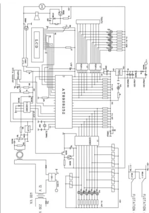
The schematic representation for controlling of the equipment for the wastewater cleaner running is illustrated in Figure 9. The equipment is placed in the control box (Figure 4) of the wastewater cleaner.
Figure 7.Detail of syringe (1) through which the intensity of the transmitted light is measured
Figure 8. Flotator with the illustration of stainless steel electrodes (3)
III. R
ESULTS AND DISCUSSIONAs the time needed to clean the wastewater during the flotation process is specific for each of the individual colors, the experimental work should be done according to used color combination. The manuscript comprises testing for the yellow color. Figure 10 comprises graphic representation of the voltage at the photodiode for the yellow color at each of the wavelengths for which the measuring was performed. The measurement was conducted every 150 seconds.
Figure 9.The schematic representation for controlling of the equipment for the wastewater cleaner
Figure 10.Graphic representation of the voltage at the photodiode for the yellow color at each of the wavelengths
The light transmittance was determined for the results of measurements at each of the wavelengths according to the following formula (4):
𝐿𝑇𝑖 = 100. 𝑈𝑖
𝑈𝑅 (4)
where
i … expresses the point order,
LTi ... light transmittance in the individual
point by order that is expressed on the main y-axis,
Ui… voltage in the individual point by order,
UR … expresses the reference voltage for the
clear water that is specific for each wavelength. Time t of measurement in the interval of 150 seconds is expressed on x-axis.
The difference, which is expressed on the minor y-axis, was determined according to the
formula (5) as the light transmittance in the following point, minus in the previous point:
𝐷𝑖𝑓𝑓𝑒𝑟𝑒𝑛𝑐𝑒 = 𝐿𝑇𝑖+1− 𝐿𝑇𝑖 (5)
The trend line was constructed to express the light transmittance tendency individually at each of the wavelengths using the statistical method of the regression with the polynomial curve fitting (6).
𝑦 = 𝑎6𝑥6+ 𝑎5𝑥5+ 𝑎4𝑥4+ 𝑎3𝑥3+ 𝑎2𝑥2+ 𝑎1𝑥 + 𝑎0
(6) Index of determination R2 was set too for every of the cases. All results for the coefficients
a6, a5, a4, a3, a2, a1 and a0 as well as the values of
index of determination R2 are arranged in Table 1. The values were managed using the program system Excel.
Figure 11.Graphic representation of light transmittance with the polynomial trend line and difference during testing the wastewater with yellow color at the wavelength of 400nm
Figure 12.Graphic representation of light transmittance with the polynomial trend line and difference during testing the wastewater with yellow color at the wavelength of 470nm
Figure 13.Graphic representation of light transmittance with the polynomial trend line and difference during testing the wastewater with yellow color at the wavelength of 530nm
Figure 14.Graphic representation of light transmittance with the polynomial trend line and difference during testing the wastewater with yellow color at the wavelength of 580nm
Figure 15.Graphic representation of light transmittance with the polynomial trend line and difference during testing the wastewater with yellow color at the wavelength of 595nm
Figure 16.Graphic representation of light transmittance with the polynomial trend line and difference during testing the wastewater with yellow color at the wavelength of 630nm
Figure 17.Graphic representation of light transmittance with the polynomial trend line and difference during testing the wastewater with yellow color at the wavelength of 950nm Using the iterative method we can determine when (for which value of t) the differences of light transmittance according to formula (5) differ slightly from the previous one. According to the obtained results we can set the proper time when the water is clean enough to be discharged into the municipal sewage. The differences (5) are very clearly displayed on the graphical characteristics according to which the most suitable cleaning time for the yellow color is 33 minutes.
Table 1.
Coefficients a6, a5, a4, a3, a2, a1 and constant a0 as well as the values for index of determination R2 of the formula (6)
Coefficients Wavelength [nm]R2a6a5a4a3a2a1a0 400 0.9990.000001 -0.00010.0041-0.06110.3881-0.74840.097 470 0.99930.000002 -0.00020.0069-0.10870.7347-1.61780.2643 530 0.9990.000001 -0.00010.0042-0.06370.5142-0.85160.5235 580 0.99920.000001 -0.00010.0044-0.06620.5625-0.55940.5803 595 0.999-0.0000000004 0.00001-0.0010.0212-0.05662.08591.6042 630 0.9994-0.0000001 0.00002-0.00120.0225-0.07042.73291.9756 950 0.9999-0.0000001 0.0001 -0.0055 0.1516 -2.2372 17.551 32.214 IV. CONCLUSION
For including the wastewater cleaner into the company's reverse logistics system, it should meet the criteria such as: the way of pollution, the amount of contaminated water and the energy demand of the cleaning process, according to company specifications. The results of the experimental work as well as the modelling show that the wastewater cleaner meets the criterion of efficiency in cleaning waste water contaminated with disperse colorants. The wastewater cleaner is constructed for water in the amount of thousands of liters per period of cleaning process. The energy demand of the cleaning process does not mean high costs for the company.
The experimental work also proved that the cleaning interval is specific according to the mixture of colors. The time interval for the cleaning process was determined using the measuring technique as well as the modelling for the contamination of the wastewater with the yellow color of the disperse colorants to 33 minutes.
ACKNOWLEDGMENT
The research was conducted as an integral part of the international scientific project 4596-6-17/19 supported by the Faculty of Management at the University of Prešov in Prešov ”Modelling of environmental management processes”.
REFERENCES
[1] ANTONYOVÁ, A., and ANTONY, P. (2015) Mathematical modelling for optimizing the electro-flotation process of water treatment.
Polish Journal of Environmental Studies, 24(2),
pp. 483-490. doi: 10.15244/pjoes/32730
[2] CLARA, M., KREUZINGER, N., STRENN, B., GANS, O., and KROISS, H. (2005) The solids retention time-a suitable design parameter to evaluate the capacity of wastewater treatment plants to remove micropollutants. Water
Research, 39(1), pp. 97-106.
doi:10.1016/j.watres.2004.08.036
[3] DEAN, J.G., BOSQUI, F.L., and LANOUETTE, K.H. (1972) Removing heavy metals from waste water. Environmental Science
and Technology, 6(6), pp. 518-522.
2018 年 6 月 DOI: 10. 3969/j. issn. 0258-2724.2018.05
JOURNAL OF SOUTHWEST
JIAOTONG UNIVERSITY
Vol.53 No.5 October. 2018[4] FAN, L., WANG, F., LIU, G., YANG, X., and QIN, W. (2014) Public Perception of Water Consumption and Its Effects on Water Conservation Behavior. Water, 6, pp. 1771-1784. doi: 10.3390/w6061771
[5] CHANG, I.-S., CLECH, P.L., JEFFERSON, B., and JUDD, S. (2002) Membrane Fouling in Membrane Bioreactors for Wastewater Treatment. Journal of Environmental Engineering, 128(11), pp. 1018-1029. doi:
10.1061/(ASCE)0733-9372(2002)128:11(1018) [6] CHEN, G. (2004) Electrochemical technologies in wastewater treatment.
Separation and Purification Technology, 38, pp.
11-41. doi: 10.1016/j.seppur.2003.10.006 [7] JARAMILLO, M.F., and RESTREPO, I. (2017) Wastewater Reuse in Agriculture: A Review about Its Limitations and Benefits.
Sustainability, 9(1734), pp. 1-19. doi:
10.3390/su9101734
[8] JOSS, A., KELLER, E., ALDER, A.C., GÖBEL, A., MCARDELL, CH.S., TERNES, T., and SIEGRIST, H. (2005) Removal of pharmaceuticals and fragrances in biological wastewater treatment. Water Research, 39(14),
pp. 3139-3152.
doi: 10.1016/j.watres.2005.05.031
[9] JUDD, S., QIBLAWEY, H., AL-MARRI, M., CLARKIN, C., WATSON, S., AHMED, A., and BACH, S. (2014) The size and performance of offshore produced water oil-removal technologies for reinjection. Separation and
Purification Technology, 134(25), pp. 241-246.
doi: 10.1016/j.seppur.2014.07.037
[10] LIDÉN, A., and PERSSON, K.M. (2016) Feasibility Study of Advanced NOM-Reduction by Hollow Fiber Ultrafiltration and Nanofiltration at a Swedish Surface Water Treatment Plant. Water, 8(150), pp. 1-15. doi: 10.3390/w8040150
[11] LIN, SH.H., and CHEN, M.L. (1997) Treatment of textile wastewater by chemical methods for reuse. Water Research, 31(4), pp. 868-876. doi: 10.1016/S0043-1354(96)00318-1 [12] MANO, T., NISHIMOTO, SH., KAMESHIMA, Y., and MIYAKE, M. (2015) Water treatment efficacy of various metal oxide semiconductors for photocatalytic ozonation under UV and visible light irradiation. Chemical
Engineering Journal, 264(15), pp. 221-229.
doi: 10.1016/j.cej.2014.11.088
[13] MIAO, X.-SH., BISHAY, F., CHEN, M., and METCALFE, CH.D. (2004) Occurrence of Antimicrobials in the Final Effluents of Wastewater Treatment Plants in Canada.
Environmental Science and Technology, 38(13),
pp. 3533-3541. doi: 10.1021/es030653q
[14] MOHAMED, Z.A. (2016) Breakthrough of Oscillatorialimnetica and microcystin toxins into drinking water treatment plants – examples from the Nile River, Egypt. Water SA, 42(1), pp. 161-165. doi: 10.4314/wsa.v42i1.16
[15] MOHAN, D., SARSWAT, A., OK, Y.S., and PITTMAN Jr., Ch.U. (2014) Organic and inorganic contaminants removal from water with biochar, a renewable, low cost and sustainable adsorbent – A critical review. Bioresource
Technology, 160, pp. 191-202.
doi:10.1016/j.biortech.2014.01.120
[16] PENG, Q., DUARTE, F., and PATON, R.S. (2016) Computing organic stereoselectivity – from concepts to quantitative calculations and predictions. Chemical Society Reviews, 45, pp. 6093−6107. doi: 10.1039/c6cs00573j
[17] RADJENOVIĆ, J., PETROVIĆ, M., and BARCELÓ, D. (2009) Fate and distribution of pharmaceuticals in wastewater and sewage sludge of the conventional activated sludge (CAS) and advanced membrane bioreactor (MBR) treatment. Water Research, 43(3), pp. 831-841. doi: 10.1016/j.watres.2008.11.043 [18] RAJESHWARI, K.V., BALAKRISHNAN, M., KANSAL, A., LATA, K., and KISHORE, V.V.N. (2000) State-of-the-art of anaerobic digestion technology for industrial wastewater treatment. Renewable and Sustainable Energy
Reviews, 4(2), pp. 135-156. doi:
10.1016/S1364-0321(99)00014-3
[19] RODGERS, J.D., and BUNCE, N.J. (2001) Treatment methods for the remediation of nitroaromatic explosives. Water Research, 35(9), pp. 2101-2111. doi: 10.1016/S0043-1354(00)00505-4
[20] SINGER, H., MÜLLER, S., TIXIER, C., and PILLONEL, L. (2002) Triclosan: Occurrence and Fate of a Widely Used Biocide in the Aquatic Environment: Field Measurements in Wastewater Treatment Plants, Surface Waters, and Lake Sediments.
Environmental Science and Technology, 36(23),
pp. 4998-5004. doi: 10.1021/Es025750i · [21] STOTTMEISTER, U., WIEßNER, A., KUSCHK, P., KAPPELMEYER, U.,
KÄSTNER, M., BEDERSKI, O., MÜLLER, R.A., and MOORMANN, H. (2003) Effects of plants and microorganisms in constructed wetlands for wastewater treatment. Biology
Advances, 22, pp. 93-117.
doi:10.1016/j.biotechadv.2003.08.010
[22] XU, P., ZENG, G.M., HUANG, D.L., FENG, CH.L., HU, SH., ZHAO, M.H., LAI, C., WEI, Z., HUANG, CH., XIE, G.X., and LIU, Z.F. (2012) Use of iron oxide nanomaterials in wastewater treatment: A review. Science of the
Total Environment, 424, pp. 1-10. doi: 10.1016/j.scitotenv.2012.02.023 參考 [1]ANTONYOVÁ , A 。 和 ANTONY , P 。 (2015)用於優化水處理電浮選過程的數學 模型。波蘭環境研究雜誌,24(2),第 483-490 頁。 doi:10.15244/pjoes/32730 [2] CLARA , M. , KREUZINGER , N. , STRENN,B.,GANS,O。和 KROISS,H。 (2005)固體保留時間 - 評估污水處理廠去 除能力的合適設計參數微量。水研究, 39 ( 1 ) , 第 97-106 頁 。 DOI : 10.1016/j.watres.2004.08.036 [3] DEAN , J.G. , BOSQUI , F.L 。 和 LANOUETTE,K.H。 (1972)去除廢水中 的重金屬。環境科學與技術,6(6),第 518-522 頁。 doi:10.1021/es60065a006 [4] FAN , L. , WANG , F. , LIU , G. , YANG,X。和 QIN,W。(2014)“公眾對 水資源消費的認知及其對水資源保護行為的 影 響 ” 。 水 , 6 , pp.1771-1784 。 doi : 10.3390/w6061771
[5] CHANG , I.-S. , CLECH , P.L. , JEFFERSON,B。和 JUDD,S。(2002)膜 污染在膜生物反應器中的廢水處理。環境工 程學報,128(11),pp.1018-1029。 doi: 10.1061/(ASCE)0733-9372(2002)128: 11(1018) [6] CHEN,G。(2004)廢水處理中的電化 學技術。分離和純化技術,38,第 11-41 頁。 doi:10.1016/j.seppur.2003.10.006 [7] JARAMILLO,M.F。和 RESTREPO,I。 (2017)農業廢水再利用:關於其局限性和 效益的評論。可持續發展,9(1734),第 1-19 頁。 doi:10.3390/su9101734 [8] JOSS,A.,KELLER,E.,ALDER,AC, GÖBEL , A. , MCARDELL , CH.S. , TERNES,T。和 SIEGRIST,H。(2005) 去除生物廢水中的藥物和香料治療。水研究, 39 ( 14 ) , pp.3139-3152 。 doi : 10.1016/j.watres.2005.05.031
[9] JUDD , S. , QIBLAWEY , H. , AL-MARRI,M.,CLARKIN,C.,WATSON, S.,AHMED,A。和 BACH,S。(2014) 海上生產的尺寸和性能用於再注入的水除油 技術。分離和純化技術,134(25),第 241-246 頁。 doi:10.1016/j.seppur.2014.07.037 [10] LIDÉN , A 。 和 PERSSON , K.M 。 (2016)瑞典地表水處理廠中空纖維超濾和 納 濾 降 低 NOM 的 可 行 性 研 究 。 水 , 8 ( 150 ) , 第 1-15 頁 。 doi : 10.3390/w8040150 [11] LIN,SH.H.和 CHEN,M.L. (1997)用 化學方法處理紡織廢水再利用。水研究,31 (4),pp. 868-876. doi:10.1016/S0043-1354 (96)00318-1 [12] MANO , T. , NISHIMOTO , SH. , KAMESHIMA,Y。和 MIYAKE,M.(2015) 各種金屬氧化物半導體在紫外和可見光照射 下用於光催化臭氧化的水處理功效。化學工 程雜誌,264(15),第 221-229 頁。 doi: 10.1016/j.cej.2014.11.088 [13] MIAO,X.-SH.,BISHAY,F.,CHEN, M。和 METCALFE,CH.D。 (2004)加拿 大污水處理廠最終廢水中抗生素的發生。環 境 科學 與技 術, 38( 13) , pp. 3533-3541. doi:10.1021/es030653q [14] MOHAMED , Z.A. ( 2016 ) Oscillatorialimnetica 和微囊藻毒素 毒素突破 飲用水處理廠 - 來自埃及尼羅河的例子。南 部 非 洲 的 水 , 42 ( 1 ) , pp.161-165. doi : 10.4314 / wsa.v42i1.16 [15] MOHAN,D.,SARSWAT,A.,OK, Y.S。和 PITTMAN Jr.,Ch.U. (2014)用生 物炭去除水中的有機和無機污染物,這是一 種可再生,低成本和可持續的吸附劑 - 一項 重要的評論。生物資源技術,160,pp. 191-202. doi:10.1016/j.biortech.2014.01.120 [16] PENG,Q.,DUARTE,F。和 PATON, R.S。 (2016)計算有機立體選擇性 - 從概念 到定量計算和預測. 化學學會評論,45,pp. 6093-6107. doi:10.1039/c6cs00573j [17] RADJENOVIĆ,J.,PETROVIĆ,M。和 BARCELÓ,D.(2009)傳統活性污泥(CAS) 和先進膜生物反應器(MBR)處理的廢水和 污水污泥中藥物的命運和分配。水研究,43 ( 3 ) , pp. 831-841. doi : 10.1016/j.watres.2008.11.043
2018 年 6 月 DOI: 10. 3969/j. issn. 0258-2724.2018.05