西 南 交 通 大 学 学 报
第 55 卷 第 4 期
2020
年 8 月
JOURNAL OF SOUTHWEST JIAOTONG UNIVERSITY
Vol. 55 No. 4
Aug. 2020
ISSN: 0258-2724 DOI:10.35741/issn.0258-2724.55.4.4
Research articleEngineering
D
ESIGN OF
U
LTRA
-W
IDEBAND
T
APERED
S
LOT
P
ATCH
A
NTENNA
WITH
R
ECONFIGURABLE
D
UAL
B
AND
-N
OTCHES
具有可重新配置的双带形缺口的超宽带锥形缝隙天线的设计
Amer Abbood Al-Behadili a , Adham R. Azeez b, Sadiq Ahmed a, Zaid A. Abdul Hassain a a Department of Electrical Engineering, Mustansiriayah University
Baghdad, Iraq, amer_osman@ uomustansiriyah.edu.iq, drsadiq18@ uomustansiriyah.edu.iq, zaidasaad_79@uomustansiriyah.edu.iq
b Department of Electronic and Communications Engineering, Uruk University
Baghdad, Iraq, adham.r.azeez@ieee.org, adham.r.azeez@gmail.com
Received: April 7, 2020 ▪ Review: June 15, 2020 ▪ Accepted: July 12, 2020
This article is an open access article distributed under the terms and conditions of the Creative Commons Attribution License (http://creativecommons.org/licenses/by/4.0)
Abstract
This paper presents an ultra-wideband tapered slot patch antenna with bi-directional radiation, reconfigurable for dual band-notched capability and fed by coplanar waveguide. The proposed antenna showed excellent ultra-wideband characteristics with bandwidth of (1.9–12 GHz). In order to reduce the interference of the narrow band communications represented by Worldwide Interoperability for Microwave Access radiation in the range (3.4–3.9) GHz and standard IEEE 802.11a. application (from 5.1 GHz to 6.1 GHz), the antenna was accompanied with adjustable dual-stop band capability in these bands. The dual-band notches are achieved with aid of inserting a parasitic single split ring resonator and etching a single circular complementary circle split ring resonator. The proposed antenna used epoxy
(FR4) substrate material with 𝜀r = 4.4 and dimensions of .
Keywords: Ultra-Wideband Antenna, Split Ring Resonator, Dual Band-Notch Antenna, Reconfigurable
Antenna 摘要 本文提出了一种具有双向辐射的超宽带锥形缝隙贴片天线,该天线可重新配置为具有双频段 陷波能力并由共面波导馈电。 拟议中的天线具有出色的超宽带特性,带宽为(1.9–12 GHz)。 为 了减少在(3.4–3.9)GHz 范围内的微波访问的全球互操作性辐射和标准电气工程师学会 802.11 一 个代表的窄带通信的干扰。 在从 5.1 GHz 到 6.1 GHz 的应用中,该天线在这些频段中具有可调的 双阻带功能。通过插入寄生单开口环谐振器并蚀刻单个圆形互补圆开口环谐振器来实现双频带陷 波。 建议的天线使用环氧树脂= 4.4 且尺寸为的环氧树脂(FR4)基板材料。
关键词: 超宽带天线,开环谐振器,双频带陷波天线,可重构天线
I. I
NTRODUCTIONAn ultra-wideband (UWB) communication
standard for industrial and commercial
applications has been introduced by the federal communication commission (FCC) [1]. The UWB antennas have acquired wide publicity for applications that require high data rates, high security, as well as low power density ( about ≤ -41dBm/MHz) [2]. However, the band allocation of UWB by the FCC is assigned to other narrow-band communication applications, such as
Worldwide Interoperability for Microwave
Access (WiMAX) (3.4 GHz–3.9 GHz), IEEE 802.11a, and HIPERLAN/2 (5.1 GHz to 5.825 GHz) [3], [4]. In order to eliminate the electromagnetic interference from these narrow-band communications, several techniques were introduced to create frequency band-notches. Several methods can be used to introduce these notches, such as creating of slots or resonators of different shapes such as U–shaped, L–shaped, complementary split ring resonators (CSRR), and split ring resonators (SRR) [2], [3], [4], [5], [6], [8]. Other techniques based on stubs have been inserted in the UWB antenna system in [3], [6] or based on of defects on the ground plane [9].
The frequency band-notches of all techniques listed above are not reconfigurable. UWB antennas with reconfigurable band-notches have attracted much research, because of its usefulness in several wireless communication systems. The
concept of the conventional band-notch
reconfiguration can be obtained with aid of adding or removing a switching element for a resonating structure or slot [7]. Switches are represented by PIN [10], varactors [11], diodes [12], MEMS [13], or photoconductive switches [14].
However, reconfigurable notches can be achieved by controlling the slot of the defective ground plane [15], or varying the length of parasitic elements [16].
In this work, an ultra-wideband (UWB)
tapered slot patch antenna with
dual-reconfigurable band-notches is introduced. The two adaptable notches are presented to reduce the interference for WiMAX radiation in the range (3.4–3.9) GHz, and the standard IEEE 802.11a. application in the range (5.1 GHz to 6.1 GHz).
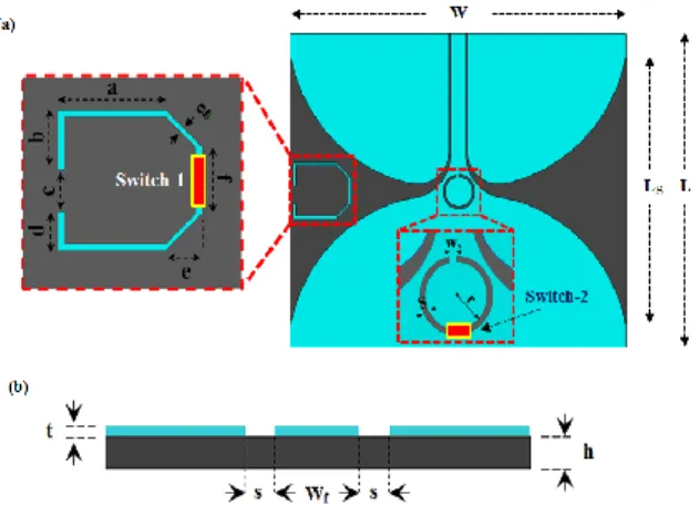
II. T
HEP
ROPOSEDA
NTENNAG
EOMETRYFigure 1 displays the suggested tapered slot antenna. The antenna consists of two symmetrical radiator tapered slots fed from a 50 Ω coplanar waveguide. The antenna is designed using FR4 substrate with dielectric constant 𝜀r = 4.4. The
substrate dimensions are 48×55×1.5 mm3. The
following is the exponential equations for the inner and outer radiation flare edges [17], [18]:
(1) (2) (3)
where y1 and y2 represent the beginning and end of the inner tapered slot, while Or represents the opening rate.
Figure 1. Basic structure of the suggested antenna: (a) Top view, (b) side view
Table 1 presents the optimal parameters for the proposed antenna structure. The UWB antenna is simulated using the high frequency structure simulator Ansoft HFSS software based on the finite-element method [19].
Table 1.
Proposed antenna optimal parameters
Parameters L W Ls h Wf Value (mm) 48 55 40.92 1.5 2.4 Parameters a b c d e Value (mm) 7.1 3.6 2.59 2.31 2.4 Parameters s t f g Value (mm) 0.29 0.018 4 0.4
The proposed tapered slot antenna structure includes two band-notch resonators. The first resonator is a quasi-trapezoidal-form parasitic single SRR resonating at 3.8 GHz (for WiMAX
3
band), while the second resonator represents a complimentary single split ring resonator (CSSRR), resonating at 5.5 GHz for IEEE 802.11a and HIPERLAN/2 (5.1 GHz to 5.825 GHz).
III. R
ECONFIGURABLED
UALB
ANDN
OTCHA
NTENNAC
HARACTERISTICSThe four switching elements are represented by two ideal electronic switches. These are represented by a thin strip line with two states, “ON” (conductive state) and “OFF” (open state). These switches are labeled as “Switch–1” and “Switch–2” (as shown in Figure 1) to yield reconfigurable band-notch properties. Table 2 shows the possible four cases based on the functionality of these two electronic switches.
Table 2.
Characteristics of band notch for four switching cases
Switch-1 Switch-2 State
(band-notch)
Case 1 OFF OFF 5.5 GHz
Case 2 OFF ON None
Case 3 ON OFF 3.8 GHz, 5.5 GHz
Case 4 ON ON 3.8 GHz
With regards to S11, the measurement and simulation results (as presented in Figure 2) were compared. Switch-1 is connected across the middle side trapezoidal conducting ring. When Switch-1 is in the ON state (short circuit), the proposed quasi trapezoidal ring produces a band-notch at the WiMAX frequency (3.8 GHz), as shown in Figure 2. However, when Switch-1 is in the OFF state (open circuit), there are no band-notch properties at the WiMAX band, as stated in Figure 2. Similarly, when Switch-2 is the ON state, the single CSRR is shorted at its middle point and subsequently split into two arc slots; there are no band-notch characteristics at IEEE 802.11a and HIPERLAN/2 (5.5 GHz). As long as, when Switch-2 is in “OFF” state (open circuit), the CSRR will resonate at 5.5 GHz and a band-notch will produced. Finally, a good agreement could be established between simulated and measured S11 with a minor difference between the results. Such difference could be due to soldering defect, SMA mismatch, substrate and copper losses and certain error in the fabricating process.
Figure 2. Simulated and measured S11 of the proposed
antennas for all switching cases
Figure 3 displays the E–and H–planes radiation patterns at different frequencies. The result showed end-fire characteristics behavior for the antenna model, which was found to be almost stable in the UWB frequency band. Figure 4 exhibits the current distribution at 3.6 GHz for case 4 and at 5.5 GHz for case 3, which allows understanding the phenomenon responsible for this band-notch performance. The current distribution through the notches frequency is concentrated about the first and second resonance. Therefore, the current distribution in other parts of the patch is weak.
E-plane H-plane
4.5 GHz
6.7GHz
10 GHz
Figure 3. Radiation patterns in principle planes (E– and H–planes) at various operating frequencies
Figure 4. Current distribution of the proposed antenna at band-notch frequencies
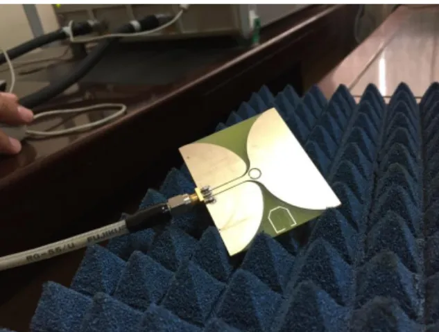
Figure 5 shows one of the suggested prototypes: dual band-notch antenna. The
proposed antenna is manufactured by using LPKF ProtoMat S100. The Anritsu Wiltron
5
MS4642B Vector Network Analyzer was
employed for the measurement. The
measurement setup employed to characterize the proposed antenna is presented in Figure 6.
Figure 5. Dual band-notch antenna prototype
Figure 6. Measurement setup for the dual-band notch antenna
IV. C
ONCLUSIONIn this design, it is available different modes. For instance, it is possible to work with single dual operation or and without band notches. The patch is printed on FR-4 substrate of
dimensions . The antenna
impedance bandwidth extends from 1.9 to 12 GHz and has adjustable dual band notches to reduce the interference mitigation in a narrow band, such as WiMAX (3.8 GHz), WLAN and HIPERLAN/2 (5.5 GHz). The band-notched properties of band are electronically reconfigured based on the PIN diode incorporated within the microstrip antenna to cancel the undesired interfering signals. By altering the states of the diodes (ON/OFF), the proposed antenna provides four frequency responses. Good consistency was observed between simulated and measured results; therefore, the proposed antenna may be utilized for the applications of UWB with high
immunity to interferences from the
electromagnetic narrow band system.
A
CKNOWLEDGMENTThe authors would like to thank the college of Engineering at Al-Mustansiriyah University, Baghdad, Iraq, https://uomustansiriyah.edu.iq/ for their support in preparing this paper.
R
EFERENCES[1] FONTANA, R.L. (2004) Recent system
applications of short pulse ultra-wideband
(UWB) technology. IEEE Transactions on
Microwave Theory and Techniques, 52 (9),
pp. 2087-2104.
[2] KIM, J., CHO, C.S., and LEE, J.W.
(2006) 5.2 GHz notched ultra-wideband
antenna using slot-type SRR. Electronics
Letters, 42 (6), pp. 315-316.
[3] CHU, Q.-X. and YANG, Y.-Y. (2008) A
Compact Ultra Wideband Antenna with
3.4/5.5
GHz
Dual
Band-Notched
Characteristics.
IEEE
Transaction
on
Antennas and Propagation, 56 (12), pp.
3637-3644.
[4] MISHRA, S.K. and MUKHERJEE, J.
(2012) Compact Printed Dual Band-Notched
U-Shape UWB Antenna. Progress in
Electromagnetics Research C, 27, pp.
169-181.
[5] NIKOLAOU, S., KINGSLEY, N.,
PONCHAK, G., PAPAPOLYMEROU, J.,
and TENTZERIS, M.M. (2009) UWB
Elliptical Monopoles with a Reconfigurable
Band
Notch
Using
MEMS
Switches
Actuated
Without
Bias
Lines.
IEEE
Transaction on Antennas and Propagation,
57 (8), pp. 2242-2251.
[6] KINGSLEY, N., ANAGNOSTOU, D.E.,
TENTZERIS,
M.M.,
and
PAPAPOLYMEROU, J. (2007) RF MEMS
Sequentially
Reconfigurable
Sierpinski
Antenna on a Flexible Organic Substrate
with Novel DC–Biasing Technique. Journal
of Microelectro–Mechanical Systems, 16 (5),
pp. 1185-1192.
[7] HASSAIN, Z.A.A., ALI, M.M., and
AZEE, A.R. (2019) Single and Dual
Band-Notch UWB Antenna Using SRR/CSRR
Resonator. Journal of Communications, 14
(6), pp. 504-510.
[8] HASSAIN, Z.A.A., OSMAN, A.A., and
AZEEZ, A.R. (2019) First order parallel
coupled BPF with wideband rejection based
on SRR and CSRR. Telkomnika, 17 (6), pp.
2704-2712.
[9] LI, Y.S., LI, W.X., and YE, Q.B. (2012)
Compact Reconfigurable UWB Antenna
Integrated with Stepped Impedance Stub
Loaded Resonator and Switches. Progress in
Electromagnetics Research C, 27, pp.
239-252.
[10] TRIPATHI, S., MOHAN, A., and
YADAV, S. (2016) A compact fractal UWB
antenna with reconfigurable band notch
functions.
Microwave
and
Optical
Technology Letters, 58, pp. 509-514.
[11] MOHAMED, H., ELKORANY, A.,
SAAD, S., and SALEEB, D. (2017) New
simple flower shaped reconfigurable
band-notched UWB antenna using single varactor
diode.
Progress
in
Electromagnetics
Research C, 76, pp. 197-206.
[12] NIKOLAOU, S., KINGSLEY, N.,
PONCHA, G., PAPAPOLYMEROU, J., and
TENTZERIS, M. (2009) UWB elliptical
monopoles with a reconfigurable band notch
using MEMS switches actuated without bias
lines. IEEE Transactions on Antennas and
Propagation, 57, pp. 2242-2251.
[13] ALNAHWI, F., ABDULHASAN, K.,
and ISLAM, N. (2015) An ultra-wideband to
dual-band switchable antenna design for
wireless communication applications. IEEE
Antennas and Wireless Propagation Letters,
14, pp. 1685-1688.
[14] MOHAMED, H., ELKORANY, A.,
SAAD, S., and SALEEB, D. (2017) New
simple flower shaped reconfigurable
band-notched UWB antenna using single varactor
diode.
Progress
in
Electromagnetics
Research C, 76, pp. 197-206.
[15] OJAROUDI, N. and OJAROUDI, M.
(2013) A novel design of reconfigurable
small monopole antenna with switchable
band notch and multi-resonance functions for
UWB applications. Microwave and Optical
Technology Letters, 55, pp. 652-656.
[16] OJAROUDI, N., GHADIMI, N.,
OJAROUDI, Y., and OJAROUDI, S. (2014)
A novel design of microstrip antenna with
reconfigurable band rejection for cognitive
radio applications. Microwave and Optical
Technology Letters, 56, pp. 2998-3003.
[17] NEVRL´Y, J. (2007) Design of Vivaldi
Antenna. Diploma thesis, Czech Technical
University.
[18] HASSAIN, Z.A.A., AZEEZ, A.R., ALI,
M.M., and ELWI, T.A. (2019) A Modified
Compact Bi-Directional UWB Tapered Slot
Antenna
with
Double
Band-Notch
Characteristics. Advanced Electromagnetics,
8 (4), pp. 74-79.
[19]
ANSOFT
HFSS
(n.d.)
[Online]
Available
from:
http://www.ansoft.com
[Accessed 12/03/20].
参考文:
[1] FONTANA,R.L。(2004)短脉冲超
宽带(超宽带)技术的最新系统应用。电
气工程师学会微波理论与技术学报,52
(9),第 2087-2104 页。
[2] KIM,J.,CHO,C.S., 和 LEE,J.W.
(2006)使用槽型 SRR 的 5.2 GHz 缺口超
宽带天线。电子信函,42(6),第
315-316 页。
[3] CHU,Q.-X。和 杨永乐(2008)具有
3.4 / 5.5 GHz 双频带陷波特性的紧凑型超
宽带天线。电气工程师学会天线和传播事
务,56(12),第 3637-3644 页。
[4] MISHRA,S.K。和 MUKHERJEE,J.
(2012)紧凑型印刷双带凹口 U 型超宽带
天线。电磁学研究进展 C,27,第
169-181 页。
[5] NIKOLAOU , S. , 金 斯 利 , N. ,
PONCHAK,G.,PAPAPOLYMEROU,J。
和 TENTZERIS,M.M.(2009)具有可重
配置带槽口的超宽带椭圆形单极子,使用
无偏置线驱动的微机电系统开关。电气工
程师学会天线和传播事务,57(8),第
2242-2251 页。
[6] N. KINGSLEY,D.E。ANAGNOSTOU,
M.M
。
TENTZERIS,
和
J.
PAPAPOLYMEROU(2007)采用新颖的
直流电偏置技术在柔性有机基板上实现射
频微机电顺序可重构谢尔宾斯基天线。微
机电系统学报,16(5),第 1185-1192 页。
[7] Z.A.A.的 HASSAIN,M.M。的 ALI, 和
A.R.的 AZEE(2019)使用 SRR/CSRR 谐
振器的单频带和双频带陷波超宽带天线。
通信杂志,14(6),第 504-510 页。
[8] HASSAIN,Z.A.A.,OSMAN,A.A。
和 AZEEZ,A.R。(2019)基于 SRR 和
CSRR 的带宽带抑制的一阶并行耦合 BPF。
特尔科姆尼卡,17(6),第 2704-2712 页。
7