Tatiana Mylläri, Aleksandr Mylläri
Dept. of Computers & Technology,
School of Arts and Sciences
St.George’s University St.George’s, Grenada, West Indies
Abstract. We use Wolfram Mathematica in teaching the basics of stere‐
oscopy. 3D graphics in Mathematica allows teachers and students to easily
construct simple stereo images and manipulate constructed images to demon‐ strate different effects and distortions introduced by incorrect methods of con‐ structing stereo images. We demonstrate basic stereoscopic effects and typical mistakes made by beginners. In particular, we demonstrate some basic tricks one can do with changing the position of the stereo window. Compactness of the Mathematica code facilitates students’ experiments and helps in under‐ standing basic concepts and ideas of stereoscopy and computer vision.
1
Introduction
Soon after the invention of photography in 1839, a first suggestion for a stereo camera was given by Brewster in 1847. By 1860 viewing stereo photos was a popular pastime
[1]. Later‐ in the 20th century‐ interest waned. Recently, with the development
of technology, interest in 3D imaging has increased: 3D cameras are available; 3Dlenses exist for cameras and smartphones; 3D cartoons and movies can be watched
on an ordinary TV or computer screen using anaglyph (red‐cyan) glasses; there are
special 3D TVs, 3D movie cinemas, glasses‐free 3D displays, etc.; and, finally, therecent development of virtual reality has stimulated interest in 3D imaging.
Modern Computer Algebra Systems (CAS)‐ for example, Mathematica, Maple,
Maxima, and others‐ provide not only opportunity for analytic and numerical cal‐ culations, but also convenient tools for image construction, manipulation and ani‐ mations. It makes CAS a good resource to use in the classroom. We use Wolfram Mathematica in teaching the basics of stereoscopy.We demonstrate basic stereoscopic effects and typical mistakes made by begin‐ ners. In particular, we demonstrate the importance of correctly choosing the stereo window and its manipulation. A stereo image can be represented as a stereopair
(for parallel and cross‐eye views). By changing the parallax of the left and right
parts of the stereogram, one can move the image (or some part of it) in front of or
behind the window frame. Our manipulations with stereo images are based on aclassic textbook by J.G. Ferwerda [1].
Figure 1: Viewing a stereo pair. Left‐to‐right: parallel view; diverging view lines;
cross‐eye view; cross‐eye view when viewing large pictures. Adopted from [1].
2
Viewing stereo pairs
There are special spectacles, glasses and masks to view stereo pairs, but it is also possible to view stereo pairs without special equipment. Two basic methods can be
used for (glasses‐) free view: the method with parallel view lines and with transverse
view lines (cross‐eye) [1], see Figure 1. One should bear in mind that view lines
should not diverge for parallel view (i.e. size of each image should not exceed 6 cm).
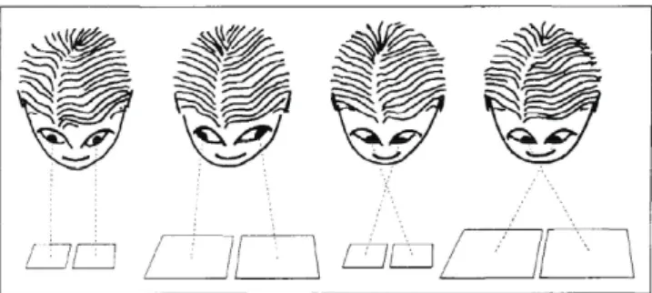
This restriction is waved for cross‐eye view, though viewing too large pictures can also cause problems.One can practice viewing stereo pairs using Figure 2. Though it was intended by
the author of [1] for practicing cross‐eye views, it can be used for practicing parallel
views as well. If one looks at Figure 2 cross‐eye (i.e., using cross‐eye view), pyramids
will be seen. If one uses parallel view, shallow (inverted) pyramids will be seen.
For many people it is easy to start with cross‐eye view: place a finger (or tip
of the pencil, etc.) between your eyes and the image and look attentively with
both eyes at it. Then start paying attention to what your finger (pencil) is actually
pointing at, without moving your eyes. In the general case the image you will seewill be double. By moving your finger closer to (or further from) the image, you can
change relative positions of these double images. Once two “ squares with crosses” coincide, you will see a stereo image. One can make a 3D image by using nearbysquares (1 and 2, 2 and 3, etc.) or every other (1 and 3, 2 and 4, etc.) ‐ in the last
case the observed pyramids will be steeper.To practice a parallel view one can try “to look through the picture” or use a
tubular view using folded paper (or just use palms) to restrict the field of view so
that each eye can see only the proper part of the image.After practicing (if one needs experience) by completing exercises successfully
(see Figures 2, 3), one can try to view a stereo image from a “real” stereo pair in
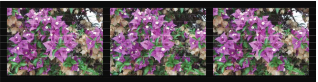
Figure 3. In this figure and further on the text a stereo image is given as a set of three pictures: LRL, where L stands for the left‐eye view and R for the right‐eyeview. The left two images (LR) should be used for the parallel view, and the right
two (RL) for the cross‐eye view.
Figure 2: The stereo exercise field. Adopted from [1].
Figure 3: Stereo image for parallel and cross‐eye view. Left pair of images should be used for parallel view, right two images‐ for cross‐eye view.
3
Experiments with stereo window
Here, we demonstrate some basic tricks one can do by changing the position of
the stereo window; and some basic mistakes of beginners (and not only beginners‐
similar mistakes can be seen in big‐screen, multi‐million‐dollar budget movies!).
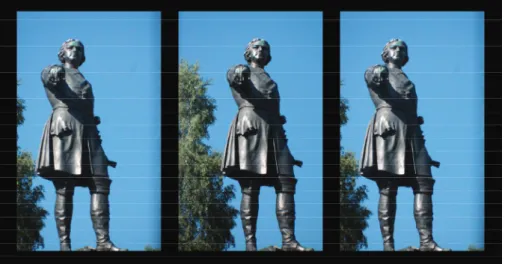
One of the standard “ Wow!” effects with 3D images is when most of the image
appears behind the frame, but part of the image is hanging out in front (see Figure
4). One has to be careful: that part shouldn’t be cut by the frame! It is especially
important in action scenes when objects which are moving around can easily be cut by the frame border. For example, in Figure 5 lower part of the image stays in front of the stereo window, and it looks impressive until one notices that at the same timeit is cut (shadowed) by the lower border of the stereo window frame that is behind
it.
The position of the object with respect to the stereo window can be changed
by shifting horizontally the left and right parts of the stereogram ([1], see also [2]
and references therein), see Figure 6. Mathematica provides good tools for image
processing and manipulation [3]. One can easily manipulate with relative parallax
of the left and right images to change the position of the image with respect to the stereo window. For example, compare series of Figures 3, 7, 8. On Fugure 3, imagestereo window.
Figure 5: Example of the bad “Wow!” effect: lower part of the image is in front of the stereo window, but it is cut by the lower border of window frame that is behind
it.
is behind stereo window. On Fugure 7 it is closer with smaller pine hanging out a little. Figure 8 gives an example of bad positioning of stereo window: foreground is in front of the stereo window, but it is cut by the window frame that is supposed to be behind it. See also Figures 9‐ 11.
4
Conclusions
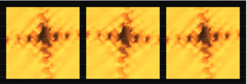
Mathematica allows easily construct simple “ artificial” stereo images that can be used for experiments. Examples are given on Figures 12 and 13.
All experiments described above can be also performed with animation. Math‐ ematica also makes easy demonstration of different distortions that could be intro‐ duced by using improper choice of line‐of‐sight, etc. Build‐in methods for solving sys‐ tems of linear and non‐linear equations make constructing random dot stereograms
(autostereograms) [4] easy. They also introduce some entertainment elements that
help keep the interest of students on the educational process.-\sim\approx\sim -\sim< -\sim_{\hat{J}}\nearrow\sqrt{1}\tilde{\ovalbox{\tt\small REJECT}}\ovalbox{\tt\small REJECT}\sim
Figure 6: One can change position of the object with respect to the window by
shifting horizontally (left or right) left and right parts of the stereogram.
Figure 7: Same as Figure 3 but relative parallax changed so that image is closer to
stereo window.
References
[1] Ferwerda J.G. The World Of 3‐D: A Practical Guide To Stereo Photography. 3‐D Production (2003)
[2] The Stereographics Developer’s Handbook ‐ Background on Creating Images for
CrystalEyes^{R}O
and SimulEyes©, StereoGraphics Corporation (1997)
[3] Hastings C., Mischo K., Morrison M. Hands‐on Start to Wolfram MATHEMATICA and Programming with the Wolfram Language. Second edition. Wolfram Media (2016) [4] Terrel M.S., Terrel R.E. Behind the Scenes of a Random Dot Stereogram. The Amer‐
Figure 8: Same as Figures 3 and 7 but relative parallax changed so that foreground on the image is in front of the stereo window.
Figure 10: Hand of the monument stays out a little while most of the image is
behind stereo window.
Figure 11: The monument is in front of stereo window, but feet are cut by the frame that is supposed to be behind it.
Figure 12: Example of the 3D image generated in Mathematica.
![Figure 2: The stereo exercise field. Adopted from [1].](https://thumb-ap.123doks.com/thumbv2/123deta/5940536.1053230/3.743.162.566.113.298/figure-stereo-exercise-field-adopted.webp)