第54卷 第4期
2019年8月
JOURNAL OF SOUTHWEST JIAOTONG UNIVERSITY
Vol.54 No.4 Aug. 2019 ISSN -0258-2724 DOI:10.35741/issn.0258-2724.54.4.35 Research article
Mathematics
I
NCLINED
M
AGNETIC
F
IELD OF
N
ON
-
UNIFORM AND
P
OROUS
M
EDIUM
C
HANNEL ON
C
OUPLE
S
TRESS
P
ERISTALTIC
F
LOW AND
APPLICATION IN MEDICAL TREATMENT
(K
NEE
A
RTHRITIS
)
应力蠕变流动中非均匀多孔介质的倾斜磁场及其在医学治疗中的
应用(膝关节炎)
Liqaa Zeki Hummady1, Iraq T. Abbas2 and Rana A. Mohammed3
1 Department of Mathematics, College of Science, University of Baghdad, Baghdad, Iraq.
2 Department of Mathematics, College of Science, University of Baghdad, Baghdad, Iraq.
3
Department of Mathematics, College of Science, University of Baghdad, Baghdad, Iraq.
Abstract
The present study analyzes the effect of couple stress fluid (CSF) with the activity of connected inclined magnetic field (IMF) of a non-uniform channel (NUC) through a porous medium (PM), taking into account the sliding speed effect on channel walls and the effect of nonlinear particle size, applying long wavelength and low Reynolds count estimates. The mathematical expressions of axial velocity, stream function, mechanical effect and increase in pressure have been analytically determined. The effect of the physical parameter is included in the present model in the computational results. The results of this algorithm have been presented in chart form by applying the mathematical program.
Keywords: inclined magnetic field (IMF), couple stress fluid (CSF), (non-uniform channel) NUC, (porous medium) PM and peristaltic flow.
摘要 : 本研究分析了耦合应力流体与通过多孔介质的非均匀通道的连接倾斜磁场的活动的影响,并考虑 了对长壁波长的滑动速度影响和非线性粒径的影响 雷诺数估算值低 解析地确定了轴向速度,流函数,机械作用和压力增加的数学表达式 物理参数的影响包括在本模型的计算结果中 该算法的结果已通过应用 程序以图表形式呈现。 关键词: 倾斜磁场耦合应力流体非均匀通道多孔介质蠕动
I.
I
NTRODUCTIONThis paper investigates the peristaltic motion of magneto hydrodynamic (MHD) non-Newtonian fluid in an inclined non-uniform channel with porous medium. Constitutive equations obeying the non-Newtonian fluid model are employed. Mathematical modeling is developed in the presence of a constant inclined magnetic field making an angle with the vertical axis. Assumptions of long wave length approximation and low Reynolds number are used in flow analysis. Closed form expressions for the stream function and mechanical efficiency are developed. Pressure rise per wave length and frictional force on the channel walls have been computed numerically. Effect of Hartman number, permeability parameter, couple stress parameter and inclination of magnetic field on the axial velocity and trapping are discussed in detail and shown graphically
.
Most of scientific problems and phenomena, especially in the field of engineering and industry, occur nonlinearly. These include extraction of crude oil from petroleum products, food mixing and chime movement in the intestine, flow of plasma, flow of blood, the movement of chime in the gastrointestinal tract and many others. The purpose of the present study is to discuss the influence of an inclined magnetic field on peristaltic flow of non-Newtonian fluid. Here is an incompressible fluid occupying the space in a non-uniform channel. Series solutions of stream function, axial velocity are given by using regular perturbation technique when wave number is small. The variations of embedded flow parameters are discussed in detail.II. R
ESEARCHA
IMThe research is aimed at studying the transfer of solids to the weight fluid via techniques for a disproportionate and non-uniform channel in a PM. The logical model of IMF sway on inclined NUC on peristaltic transport of CSF and PM is discussed in this paper.
III. L
ITERATURER
EVIEWClearly, the mixing and transport of physiological fluids is known as peristalsis, which can be gotten by repeated deluges of pressure of the zone and included along the barrel containing fluid containing fluid. The unconstrained technique behind this wonder is
essentially the musculoskeletal game plan of any smooth adjusted muscle structure. This assault of the musculoskeletal divider indicates advancement in the wave diagram in sorts of confined speed and wave length. This segment is open in the trading of pee from the kidney to the bladder, similarly as the improvement of ringing in the gastrointestinal tract, fluid in the lymphatic vessels, and the yellow from the gallbladder to the twelve, and the advancement of sperm in the channels out of the male regenerative structure, the advancement of the egg in the fallopian tube, Little veins. The majority of sensible issues and wonders especially assembling, geology, happen nonlinearly. CSF is one of them. Various practical applications include biomechanical systems. In a similar manner, finger and roller siphoning are intermittently used for siphons damaging or unadulterated materials to prevent direct contact of the fluid with the siphons inside surfaces. Additionally, by applying the rule of peristalsis, some biomechanical instruments, e.g., a heart-lung machine have been manufactured. The examination of CSF fluid is profitable in understanding distinctive physical issues since it has the framework to depict rheological complex fluids, for instance, liquid valuable stones and human blood. By techniques for CSF (couple stress ) fluids, we mean the liquid whose particles are considered, an extraordinary case of non-Newtonian fluid. Some progressing examinations have confirmed the trading of MHD [1]-[5]. Some ongoing examinations have been directed on the transient exchange of pressure liquid by [6]-[9]. Diverse examinations on the marital weight fluids we have as of late referenced are blood as a CSF and have been performed applying a non-slip state, despite the way that in veritable structures there is constantly a particular proportion of slippage. The thermodynamic parts of blood may not be indispensable when the blood is inside the body yet it winds up basic when it is pulled out of the body. Considering the hugeness of HT in circulation system [10] we analyzed the thermodynamic pieces of circulatory system in the blood-viewing tube as the Cassone liquid [11].
IV. R
ESEARCHM
ETHODSConsider the peristaltic stream of an incompressible CSF through non-uniform channel (NUC) with PM under the activity of
(IMF) created by spread of waves on the channel walls (CWs) going with various amplitudes and stages yet with steady speed c (see Figure 1). Let Y* = and Y* = represent the upper wall (UW) and UW (LW) of the channel, respectively, such that
(1)
(2) where a1 and a2 are the amplitudes of waves, λ is the wave length, 0 (0< < ) the phase
difference between the CWs. X* and Y* are the rectangular Cartesian coordinates with X* measures the axis of the channel and Y* the transverse axis perpendicular to X*; d1 and d2 are the height constants of the UW and LW of the channel from the central line and a denotes the inclination of the CWs with the central axis- X*. ―The relation between Q and q in Eqs.(13) and (14) can be obtained as
Figure 1: A physical sketch of the problem The governing motion equations for unsteady flow through an NUC of an incompressible CSF [8], [9] with IMF (3) + – (4) + + - (5)
where V =(U*, V*, 0) is the speed vector, P* is the pressure, - the fluid density, - the viscosity of the fluid, is the constant associated with CSF effect, the constant IMF , denotes the electrical conductivity of the fluid.
And
The laboratory frame (X*, Y*) and wave frame (x*, y*) are treated as unsteady and steady motion respectively. Considering the relation between the wave frame (x*, y*) moving with a velocity c away from a fixed frame (X*, Y*). In addition to equation (4) and (5) become
v* (x* ,y*) = V*, y* = Y *, x*= X* — ct*, U*=u* (x*, y*)+c
Therefore, (u*, v*) and (U*, V*) are respectively the velocity components in the wave and laboratory frames. This means that the governing Eqs. (3), (4) and (5) can be written in the wave frame (6) + (7) + + (8) By using the non-dimensional variables [10].
, c*=c-c0, ,
where (
is the wave number, (Re) is the Reynolds number, (Ha) is the Hartmann number, ( ) represents CS parameter, w.(9)
The velocity components u and v are given by ,
Such that , being the stream function representation of the non-dimensional variables defined in Eqs. (6), (7), (8), gives the following equation
(11)
(12)
The volumetric flow rate is given by
(13) where h1 and h2 are functions of X* and similarly, the rate of volume flow in the wave frame is obtained as
(14) (15) The time mean flow over a period T at a fixed position X* is defined as
(16) And using Eq. (15) in Eq. (16) we obtain:
(17)
Note that h1 (x) and h2 (x) represent the dimensionless form of the peristaltic CWs given by
(18) (19) where
Representation of the non- uniform parameter of the channel and the dimensionless form Eq. (17) is now given by
(20)
(21) Under the assumption of LWL approximation (S<< 1) and low Re, [7] eliminating pressure term using cross differentiation from the dimensionless Eqs. (11) and (12) one can write in a single differential equation in terms of stream function as
(22) With boundary conditions as [11]
(23) We can find the solution
+ (24)
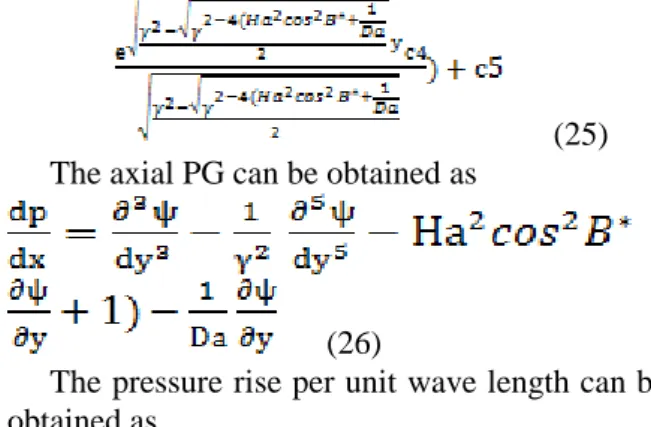
The velocity can be written as
(25) The axial PG can be obtained as
(26)
The pressure rise per unit wave length can be obtained as
(27) The mechanical efficiency is the ratio of the average rate per wavelength at which work is done by the moving fluid against a pressure head and the average rate at which the work on the fluid. It is derived as I p E Q (28) where dx x x p I 1 sin(2 ) 0 (29) and c6 are constants that can be determined from the boundary conditions Eq.( 23).
V. R
ESULTSThe explanatory articulations for the axial velocity (AV), mechanical efficiency (ME), and pressure rise are determined in this area. The numerical outcomes comparing to the previously mentioned logical articulations have been figured utilizing MATHEMATICA software, seem diverse parameter in this paper such as Hartmann number (Ha), Darcy number (Da), CS parameter ( ), NU parameter (k), inclined magnetic constant (B*), phase difference ( ) and Slip Parameter (B).
1. Mechanical efficiency
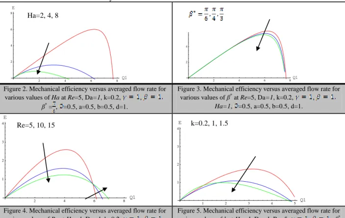
Equations (28) and (9) are plotted through Figures 2-9 to show the connection between mechanical productivity (E) and the normal stream rate (Q) and to think about the varieties of mechanical proficiency for various physical parameters (
*, Re, Ha, k, B, , , Da). Figure 2 shows that mechanical efficiency decreases with increasing (Ha), however in Figure 6, the mechanical efficiency has an opposite behavior with increasing Figure 3 shows a decrease inmechanical efficiency with increasing (
*). Figure 4 demonstrates that mechanical efficiency decreases for Q1<6 and increases for Q1>6 with the increasing (Re). There is an increase in the mechanical efficiency for Q1<0.98 and decrease for Q1>0.98 with the increasing (k) (Figure 5). The mechanical efficiency decreases with increasing ( ) (Figure 7). Figure 8 shows that there is a decrease in mechanical efficiency for Q1<0.4 and increases for Q1>0.4 with increasing (Da). And in Figure 9 we can see an increase in mechanical efficiency with increasing (B). 2. Pumping characteristicFigures 10-17 demonstrate the variety of pressure rise in capacity of volumetric stream rate in the wave outline for various estimations of the Hartmann number (Ha), inclined magnetic parameter (
*), CS parameter ( ), Reynolds number (Re), the slip parameter (B), Darcy number (Da), phase difference ( ), and the NU parameter (k). The whole region is divided into five parts (i) peristaltic pumping region where(Δp > 0, F >0); (ii) augmented pumping
(co-pumping) region where (Δp < 0, F > 0). (iii) when (Δp > 0, F < 0), (iv) a retrograde pumping region with a co-pumping region where (Δp <0, F < 0) and (v) (Δp = 0) corresponding to the free pumping region. Figure11 shows that pressure rise Δp increases with increasing Hartmann number Ha. It can be seen from the graph that in a retrograde region (Δp > 0, F < 0), the pumping rate decreases in a co-pumping region where (Δp <0, F < 0) with an increase in Ha. Figure 10 shows that pressure rise Δp decreases with increasing NU parameter. It is observed that the pumping rate increases in the co-pumping region
(Δp < 0) and free pumping region (Δp = 0).
Figure 12 shows that pressure rise Δp decreases with increasing slip parameter B. It is observed that in a retrograde pumping region (Ap >0, F < 0), the pumping rate increases a co-pumping region where (Δp < 0) with an increase in B. Figure 13 shows that pressure rise Δp decreases with increasing CS parameter . It is observed that in a retrograde pumping region (Δp >0, F <0), the pumping rate increases in a co-pumping region where (Δp < 0) with an increase in . Figure14 shows that pressure rise Δp increases with increasing inclined magnetic
*. It can be seen from the graph that in a retrograde region(Δp > 0, F < 0), the pumping rate decreases in a
co-pumping region where (Δp <0, F < 0) with an increase in
*. Figure 15 shows that pressure rise Δp decreases with increasing Darcy number (Da). It is observed the pumping increases in the region of augmented pumping and the co-pumping region (Δp < 0). Figure16 that an increase in RN Re results in an increase in retrograde pumping rate (Δp > 0, F < 0) and also an increase in the pressure rise. It is noticed that there is a linear relationship between pressure rise for each wave length and volumetric flow rate. Figure 17 shows that pressure rise Δp increases with increasing phase different in a retrograde pumping region. It is observed that the pumping rate decreases in the co-pumping region(Δp < 0) with an increase in the phase difference
.
3. Velocity distribution
Figures 18-23 represent the variation of axial velocity (AV) across the channel for different values of the Hartmann number (Ha), CS parameter (γ), the slip parameter (B), the Darcy number (Da), phase difference ( ) and the NU parameter (k). Figure 18 shows that the AV decreases in the central region of the channel with increasing Hartmann number (Ha), while the AV increases in the boundary of the channel
wall. The reason behind this fact is the Lorentz force that arises due to the application of an EMF, which plays a vital role in decelerating the fluid motion. Similarly, the AV has reducing effect at the central region of the channel and accelerating effect near the CWs for increasing CS parameter γ as shown in Figure 19 In this case velocity decreases due to the increase of particle size suspended in the fluid itself and causes flattening of the velocity profiles. In order to satisfy the conservation of mass, the flow rate remains the same for any value of these parameters at any cross section of the channel.
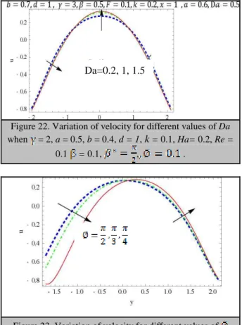
The AV also decreases at the central region with increasing the slip effect parameter β of the channel, while the AV increases in the boundary of the channel wall (Figure 20) as well as the AV also decreases at the central region with increasing the non-uniform parameter k of the channel, while the AV increases in the boundary of the channel wall (Figure 21).The AV increases at the central region with the increase of the Darcy number (Da), while the AV decreases in the boundary of the channel wall (Figure 22). Figure 23 shows that the AV decreases in the central region of the channel with increasing the phase difference parameter , while the AV increases near the CWs.
Figure 2. Mechanical efficiency versus averaged flow rate for various values of Ha at Re=5, Da=1, k=0.2, ,
β*
= , =0.5, a=0.5, b=0.5, d=1.
Figure 3. Mechanical efficiency versus averaged flow rate for various values of β* at Re=5, Da=1, k=0.2, ,
Ha=1, =0.5, a=0.5, b=0.5, d=1.
Figure 4. Mechanical efficiency versus averaged flow rate for various values of Re at Ha=1, Da=1, k=0.2, ,
Figure 5. Mechanical efficiency versus averaged flow rate for various values of k at Ha=1, Da=1, Re=5, , β*
2 4 6 8 Q1 2 4 6 8 E 2 4 6 8Q1 2 4 6 8 E 2 4 6 8 Q1 1 2 3 4 E 1 2 3 4 5 Q1 1 2 3 4 E Ha=2, 4, 8 Re=5, 10, 15 k=0.2, 1, 1.5
β*
= , =0.5, a=0.5, b=0.5, d=1. = , =0.5, a=0.5, b=0.5, d=1.
Figure 6. Mechanical efficiency versus averaged flow rate for various values of at Ha=1, Da=1, Re=5, , β*
= , =0.5, a=0.5, b=0.5, d=1.
Figure 7. Mechanical efficiency versus averaged flow rate for various values of at Ha=1, Da=1, Re=5, ,
β* = , =0.2, a=0.5, b=0.5, d=1.
Figure 8. Mechanical efficiency versus averaged flow rate for various values of Da at Ha=1, =0.5, Re=5, , β*
= , =0.2 ,a=0.5, b=0.5, d=1.
Figure 9. Mechanical efficiency versus averaged flow rate for various values of at Ha=1, Da=1, Re=5, ,
β* = , =0.2, a=0.5, b=0.5, d=1.
Figure 10. Variation of pressure rise ΔP with F for different values of K when Da =0.1, = 2, a = 0.5, b = 0.4, d = 1, =
0.1, Ha = 0.2, Re = 0.1, .
Figure 11. Variation of pressure rise ΔP with F for different values of Ha when Da =0.1, = 2, a = 0.5, b = 0.4, d = 1,
= 0.1, , K = 0.2, Re = 0.1, Fr = 0.05,
Figure 12. Variation of pressure rise ΔP with F for different values of when Da =0.1, = 2, a = 0.5, b = 0.4, d = 1, =
0.1, Ha= 0.2, Re = 0.1, .
Figure 13. Variation of pressure rise ΔP with F for different values of when Da =0.1, k = 2, a = 0.5, b = 0.4, d = 1, = 0.1, , Ha= 0.2, Re = 0.1, . 2 4 6 8 10 Q1 2 4 6 8 E 0.1 0.2 0.3 0.4 0.5 Q1 0.05 0.10 0.15 0.20 E 0.1 0.2 0.3 0.4 0.5 Q1 0.05 0.10 0.15 0.20 E 0.1 0.2 0.3 0.4 0.5 0.6 Q1 0.05 0.10 0.15 0.20 0.25 0.30 E =0.2 ,1,1.5 Da=0.2, 1, 1.5 Ha=0.1, 2, 2.5 k=0.2, 0.4, 0.6
Figure 14. Variation of pressure rise ΔP with F for different values of when = 2, a = 0.5, b = 0.4, d = 1, k = 0.1, Ha=
0.2, Re = 0.1, .
Figure 15. Variation of pressure rise ΔP with F for different values of Da when = 2, a = 0.5, b = 0.4, d = 1, k = 0.1,
Ha= 0.2, Re = 0.1, = 0.1, , .
Figure 16. Variation of pressure rise ΔP with F for different values of Re when Da =0.1, = 2, a = 0.5, b = 0.4, d = 1, k =
0.1, Ha= 0.2, .
Figure 17. Variation of pressure rise ΔP with F for different values of when Da =0.1, = 2, a = 0.5, b = 0.4, d = 1, k
= 0.1, Ha= 0.2, Re = 0.1, B = 0.05.
Figure 18. Variation of velocity for different values of Ha when Da =0.1, = 2, a = 0.5, b = 0.4, d = 1, = 0.1, , K =
0.2, Re = 0.1, Fr = 0.05, .
Figure 19. Variation of velocity for different values of when Da =0.1, k = 2, a = 0.5, b = 0.4, d = 1, = 0.1,
, Ha= 0.2, Re = 0.1, .
Figure 20. Variation of velocity for different values of when Da =0.1, = 2, a = 0.5, b = 0.4, d = 1, = 0.1, Ha= 0.2, Re =
0.1, .
Figure 21. Variation of velocity for different values of K when Da =0.1, = 2, a = 0.5, b = 0.4, d = 1, = 0.1, , Ha = 0.2, Re = 0.1, . Da=0.2, 1, 1.5 Re=5, 10, 15 k=0.2, 0.4, 0.6 Ha=0.1,2,2.5
Figure 22. Variation of velocity for different values of Da when = 2, a = 0.5, b = 0.4, d = 1, k = 0.1, Ha= 0.2, Re =
0.1 = 0.1, , .
Figure 23. Variation of velocity for different values of when Da =0.1, = 2, a = 0.5, b = 0.4, d = 1, k = 0.1, Ha=
0.2, Re = 0.1, B = 0.05.
VI. S
UGGESTIONS FOR PRACTICAL USEThis work was used as an application to clarify the treatment of knee inflammation resulting from stiffness and wear of cartilage, which is one of the most significant causes of joint pain. The cartilage is the flexible part of the porous tissue, which contains the synovial fluid, separating the two members in the channel that represents the mathematical model in this problem. Figure 24 shows the structure of the knee joint cartilage.
Figure 24. The structure of knee joint cartilage as an application (NU channel with PM)
1. Arthritis of the knee
The most common knee problems are stiffness or cartilage erosion. Cartilage acts as a cushion separating the bones and cartilage disease (a progressive process of erosion in the knee joint cartilage). This occurs naturally between 35-40 years of age and increases with age and occurs due to blockage in the fine capillary membranes feeding the joint and the sinus membrane surrounding the cartilage, which leads to less secretion of synovial fluid inside the joint which is an oily fluid that makes the cartilage flexible and reduces friction between the bones. When the secretion hardens, the cartilage slowly leads to friction bones, resulting in arthritis [17]. 2. Treatment for cartilage dysplasia
The acid injected in the cartilage is a substance similar to the synovial fluid, and it works in a similar way on the CS principle of the fluid, giving elasticity to the cartilage, and shows the parameter (γ).
Physiotherapy ultrasound leads to the generation of a magnetic field, which alleviates pain and stimulates the synovial fluid movement The physiotherapy works on the principle of increasing the inclined magnetic field IMF and also notes increase in the approved parameters (Ha) and (B*). Figure 25 demonstrates the treatment of cartilage by the injection method (CS fluid effect).
Figure 25. Cartilage treatment by the injection method
VII. C
ONCLUSIONSIn this paper, we have theoretically studied the effects of the IMF and CS of physiological fluids, represented by a non-Newtonian fluid model passing through an asymmetric and NU channel with PM under the LWL and low RN assumptions. In this investigation, special emphasis has been paid to studying velocity distribution—the pumping characteristic and mechanical efficiency on the basis of a simple analytical solution. This was applied in the medical field to treat cartilage stenosis, a Da=0.2, 1, 1.5
condition leading to knee inflammation where the cartilage is inflamed by NU channel with PM. Medical treatments such as synovial injection (effect CS), physiotherapy of the ultrasound and magnetic field (effect IMP), and the effects of parameters on the movement of the synovial fluid inside and on both sides of the cartilage wall (γ), (Ha) and (B*).
- The mechanical efficiency increases with increasing (Da), (B), ( ), (Re) and decreases with the increasing (γ), (Ha), (k) and (B*).
- The AV(u) decreases at the central region with the increasing values of the Hartmann number (Ha), CS parameter (γ), the inclined parameter (B*) and NU parameter (k) of the channel, whereas it increases at the boundary of the channel wall.
- The AV(u) increases at the central region with the increasing values of the Darcy number (Da) and decreases at the boundary of the channel wall.
- There is a linear relationship between the pressure rise for each wave length and volumetric flow rate.
- The pressure rise increases in retrograde pumping with the increasing values of (B), (Ha) and (Re) and decreases with the increasing values of (Da),(γ), (k) and (B*) .
- When the cartilage is injected with fluid, the effect of (CS) increases with the parameter (γ), which leads to a decrease in the fluid velocity (AV) inside the joint and increases at the boundary as in Figure 19. The injection of the cartilage with fluid reduces friction and inflammation.
- The exposure of the knee joint to the ultrasound waves and the generated magnetic field (IMF) lead to the increase in the parameters (Ha) and (B*), to the decrease in the fluid velocity (AV) inside the joint and the increase at the boundaries as in Figures 18 and 20, resulting in the oily wall cartilage, reduced friction and inflammation.
- Mechanical friction of the cartilage wall (ME) is reduced the greater the treatment by injection or physiotherapy due to the increase of parameters (γ), (Ha) and (B*) (Figures 2, 3 and 7) which in turn increase the fluid on the wall becomes a moist, flexible and low friction and thus less knee arthritis
R
EFERENCES[1] SANDEEP, N., and SUGUNAMMA, V.
(2014) Radiation and IMF effects on
unsteady hydromagnetic free convection
flow past an impulsively moving vertical
plate in a PM. Journal Application
Mathematic Fluid Mechanic. 7, pp.
275-286.
[2] BRANOVER,
H.
(1978)
Magneto
Hydrodynamics Flow in Ducts. New
York: Wiley.
[3] AJAZ, A.D. and ELANGOVAN, K.
(2016) Thermal diffusion, radiation and
IMF effects on oscillatory flow in
asymmetric channel in presence of heat
source and chemical reaction. Journal of
the Nigerian Mathematical Society, 35,
pp. 488-509.
[4] HAYAT, T., KHAN, M., and ASGHAR,
S. (2007) Peristaltic transport of a third
order fluid under the effect of a magnetic
field. Application Mathematic Computer,
53, pp. 1074-1087.
[5] HAYAT, T., MAHOMED, FM. and
ASGHAR, S. (2005) Peristaltic flow of a
magnetohydrodynamic
Johnson-Segalman fluid. Nonlinear Dynamic, 40,
pp. 375-85.
[6] MEHMOOD, O.U. and HAYAT, T.
(2011) Slip effect on MHD flow of third
order fluid in a planar channel,
Communications in Nonlinear Science
and Numerical Simulation 16(3), pp.
1363-1377.
[7] SALMAN, A.D., KHALAF, O.I., and
ABDULSAHIB,
G.M.
(2019)
An
adaptive intelligent alarm system for
wireless sensor network. Indonesian
Journal of Electrical Engineering and
Computer Science, 15(1), pp. 142-147.
[8] HAYAT, T., AWAIS, M., SAFDAR, A.,
and HENDI, A.A. (2012) Unsteady three
dimensional flow of couple stress fluid
over a stretching surface with chemical
reaction. Nonlinear Analysis: Modelling
and Control, 17(1), pp. 47-59.
[9] MANSUR, S., ISHAK, A. and POP, I.
(2014) Flow and heat transfer of
nanofluid past shrinking/stretching sheet
with partial slip boundary conditions,
Journal Application Mathematic Fluid
Mechanic ,35, pp.1401-1410.
[10] MOHANKRISHNA,
P.,
SUGUNAMMA, V. and SANDEEP, N.
(2014) Radiation and magnetic field
effects on unsteady natural convection
flow of a nanofluid past an infinite
vertical plate with heat source. Chemical
Process Engineering Research, 25, pp.
39-52.
[11] KRISHNAMURTHY,
M.R.,
PRASANNAKUMARA,
B.C.,
GIREESHA, B.J., GORLA, R.S. (2015)
Effect
of
viscous
dissipation
on
hydromagnetic fluid flow and heat
transfer
of
nanofluid
over
an
exponentially stretching sheet with
fluid-particle suspension. Cogen Mathematic,
2(1), 1050973, pp. 1-18.
[12] AGARWAL,
R.P.
(1989)
Heat
transfer to pulsatile flow of conducting
fluid in a porous channel. Phd Thesis,
Allahabad.
[13] HANAA, A. and ABDULHADI, M.A.
(2015) Peristaltic Transport of Couple
Stress
Fluid
through
an
Inclined
Asymmetric and Non- Uniform Channel
with Porous Medium, International
Journal of Science and Research (IJSR),
article no. 23197064, pp. 1405- 1413.
[14] MUTUKU-NJANE,
W.N.
and
MAKINDE,
O.D.
(2014)
MHD
nanofluid flow over a permeable vertical
plate with convective heating. Journal of
Computational
and
Theoretical
Nanoscience, 11(3), pp. 667-675.
[15] NADEEM, S., HAQ, R. U. and
KHAN, Z. H. (2014) Heat transfer
analysis of water-based nanofluid over
an
exponentially
stretching
sheet.
Alexandria Engeneering Journal, 53, pp.
219-224.
[16] KHALAF, O.I., ABDULSAHIB, G.M.,
and SADIK, M. (2018) A Modified
Algorithm for Improving Lifetime WSN.
Journal of Engineering and Applied
Sciences, 13, pp. 9277-9282
[17] VREZAS, I. ELSNER,
G.
BOLM-AUDORFF,
U.
ABOLMAALI,
N.
SEIDLER, A. (2010) Case-control study
of knee osteoarthritis and lifestyle factors
considering
their
interaction
with
physical
workload.
International
Archives
of
Occupational
and
Environmental Health; 83(3), pp.
291-300.
参考文:
[1]SANDEEP,N.和SUGUNAMMA,V.(201 4)辐射和IMF对通过PM中脉冲移动垂直 板的不稳定磁流体自由对流的影响。期刊 应用数学流体力学。 7,第275-286页。 [2]BRANOVER,H.(1978)管道中的磁流体 动力学流动。纽约:威利。 [3]AJAZ,A.D.和ELANGOVAN,K.(2016) 在存在热源和化学反应的情况下,热扩散 ,辐射和IMF对非对称通道中振荡流的影 响。尼日利亚数学学会杂志,第35卷,第4 88-509页。 [4]HAYAT,T.,KHAN,M.和ASGHAR,S. (2007)在磁场作用下蠕动传输三阶流体 。应用数学计算机,53,第1074- 1087页。 [5]HAYAT,T.,MAHOMED,FM。和ASGH AR,S.(2005)磁流体动力学Johnson-Segalman流体的蠕变流。非线性动态,第4 0卷,第375-85页。 [6]MEHMOOD,O.U。和 HAYAT,T.(2011)滑动对平面通道中三 阶流体MHD流动的影响,《非线性科学与 数值模拟通讯》 16(3),1363-1377页。 [7]SALMAN, A.D., KHALAF, O.I.,
和ABDULSAHIB,
G.M.
(2019)用于无线传感器网络的自适 应智能警报系统。印尼电机工程与计算机 科学杂志,15(1),第142-147页。 [8]HAYAT,T.,AWAIS,M.,SAFDAR,A. 和HENDI,A.A.。 (2012)耦合应力流体在具有化学反应的 拉伸表面上的不稳定三维流动。非线性分 析:建模与控制,17(1),第47-59页。 [9]MANSUR,S.,ISHAK,A.和POP,I.(20 14)纳米流体通过具有部分滑移边界条件的收缩/拉伸片的流动和传热,期刊应用数学流 体力学,35,第1401-1410页。 [10]MOHANKRISHNA,P.,SUGUNAMMA ,V.和SANDEEP,N.(2014)辐射和磁场对 通过无限垂直板的热流体对纳米流体不稳定 自然对流的影响。化学过程工程研究,25, 第39-52页。 [11]KRISHNAMURTHY,MR,PRASANNA KUMARA,B.C。GIREESHA,B.J.,和GOR LA,R.S(2015)粘性耗散对水磁流体流动和 纳米流体在具有流体颗粒悬浮液的指数拉伸 片材上的传热的影响。科恩数学,2(1),1 050973,第1-18页。 [12]AGARWAL,R.P。(1989)在多孔通道 中将热传递至传导流体的脉动流。博士学位 论文,阿拉哈巴德。 [13]HANAA,A.和ABDULHADI,M.A.(201 5)蠕动传输耦合应力流体通过带有多孔介质 的倾斜的非对称和非均匀通道,国际科学与 研究杂志(IJSR),第1号。 23197064,第1405-1413页。 [14]
![Figure 1: A physical sketch of the problem The governing motion equations for unsteady flow through an NUC of an incompressible CSF [8], [9] with IMF (3) + – (4) ++ - (5)](https://thumb-ap.123doks.com/thumbv2/123deta/8048608.1255331/3.892.104.414.634.843/figure-physical-sketch-problem-governing-equations-unsteady-incompressible.webp)