1. Introduction
Herodotus (III. 60) described Eupalinos’ aqueduct and tunnel on Samos as one of the greatest works of ancient world. The tunneling started from both ends at the same time, and the two tunnels met approximately in the middle. This technique required the engineer to plan and lay out the tunnels before the construction, and to control measurement during construction work. Such techniques did not exist before the 8th century B.C.
1)The tunnel of Eupalinos is one of the oldest tunnels in the world which was constructed by this counter-tunnel technique.
The tunnel of Eupalinos aimed to bring water from behind of a mountain to the ancient city of Samos. The construction period is considered to have been 550–530 B.C. from the evidence of archaeological ndings.
2)The aqueduct of Samos consists of three parts; the aqueduct from the spring to the tunnel, the main part of the tunnel, and the aqueduct from the tunnel to the city of Samos. The spring of Agiades was found behind Mt. Ampelos to the northwest of the city (Fig. 1). The tunnel is 1,043 m in total length (new measurement), and its section is about 1.80 × 1.80 m. The section of the tunnel is shaped like a �: there is a channel along the east side of the tunnel, in which a terracotta pipeline runs (Figs. 2, 3). The mountain consists of hard limestone throughout the entire tunnel.
Since the tunnel was rediscovered in the nineteenth century, there have been many investigations mostly by German archaeologists. In 1882, the tunnel was discovered by a local monk from the monastery of Agia Triada; however the tunnel had been closed and forgotten for more than ninety years until the second discovery. From 1971 to 1973, the tunnel was excavated by the German Archaeological Institute (DAI). Hermann J. Kienast continued the research on the tunnel, and published the results as a Samos series.
3)Nevertheless Kienast did not report the closing error of the main traverse of his survey, and the accuracy of his drawings and measurements is unclear. In addition, Kienast did not discuss the distance and angle measurements of the tunnel in his analysis.
Under these conditions, the present author had an opportunity to join a new survey of the tunnel of Eupalinos in 2009. The purpose of the project was to investigate and restore the tunnel, which had not been cleaned up after the previous excavation and had been endangered by natural catastrophes. This project was conducted by the Ministry of Culture of the Greek Government, with a science committee containing several specialists: surveyors, architects, geologists and civil engineers. The author joined as a member of the survey team (leader: Prof. K. Tokmakidis), and measured the detail of the tunnel.
4)The present article
GENERAL DESCRIPTION OF THE AQUEDUCT TUNNEL OF EUPALINOS IN ANCIENT SAMOS
New survey by use of digital measurement techniques
サモスのエウパリノスの水道トンネルの現状
デジタル測量技術を用いた実測調査
�� ��
*Ryuichi YOSHITAKE
In about 540 B.C., the Greek engineer Eupalinos dug a tunnel over 1 km long through a mountain to bring water from a spring on its far side into the city of Samos on the Greek island of the same name. The tunnel was dug from both ends to meet in the middle. Since the tunnel was rediscovered in the nineteenth century, there have been several investigations. The present article reports a new measurement of the tunnel using modern instruments and a reinvestigation of the construction strategy. The new measurements confirm the professionalism of the original design; the two ends of the tunnel start accurately in direction and slope. The tunnel from the northern end deviates from the line but makes correcting turns. The tunnels meet with a difference in height of only 64 cm. This accuracy shows that there would have been continual measurement and reassessment of the progress of the tunnels. The instruments of the time that are known to us would not have been suf cient for these tasks. New measurements and observations demonstrate the skill and talent of Eupalinos in managing this project.
Keywords : Eupalinos, Aqueduct Tunnel, Samos, Architect, Digital Measurement Technique
エウパリノス , 水道トンネル , サモス , 建築家 , デジタル測量技術* Assist. Prof., Dr. Eng., Priority Organization for Innovation and Excellence, ������������������� � �� � 計画系 673 号
【カテゴリーⅡ】 日本建築学会計画系論文集 第77巻 第673号,715-721,2012年3月 J. Archit. Plann., AIJ, Vol. 77 No. 673, 715-721, Mar., 2012
GENERAL DESCRIPTION OF THE AQUEDUCT TUNNEL OF EUPALINOS IN ANCIENT SAMOS
New survey by use of digital measurement techniques サモスのエウパリノスの水道トンネルの現状
デジタル測量技術を用いた実測調査
Ryuichi YOSHITAKE
* 吉 武 隆 一* Assist. Prof., Priority Organization for Innovation and Excellence, Kumamoto University, 熊本大学大学院先導機構 特任助教・博士(工学)
Dr. Eng.
Fig. 1 Topographical map of ancient city of Samos Fig. 2 Section of the tunnel (about 200m from the north entrance)
Fig. 3 View of the tunnel, about 65 m from south entrance (near S105) Fig. 4 View of point cloud, about 65 m from south entrance (near S105) aims to present the results from the new survey and observation of the strategy of the tunnel construction.
2. Measurement methods
Kienast had made drawings with detailed information on measurements; however, not all parts of the tunnel were drawn, probably because of the limitations of the measuring techniques at that time. In our research, new digital measuring instruments are used; a non-re ective total station, a GPS and a 3D Laser Scanner. The measurement method was as follows. First, a control network of points was established by GPS, using dual frequency geodetic receivers. Some base points were established near the two entrances of the tunnel, and these base points are referenced to the local coordinates.
In order to set up the base points in the tunnel, a digital total station (Leica Geosystems TS09) with 1-second accuracy for angles and 2 mm accuracy for distances was used. This total station was used in the measurement both of the traverse and of detail points. The main traverse through the tunnel had 65 base stations over a total length of more than 1 km. A closed traverse was made by measuring over the mountain through which the tunnel runs. The loop closure error was 7 mm in horizontal and 13 mm in vertical distance. This means all the measuring results from the base stations are reliable with an accuracy of ca. 1 cm.
The rst task of preparing for measurement was to install number plates at intervals of 10 m on the tunnel wall in order to nd the base point easily, because most of the inside of the tunnel looks very similar. The plates were made of stainless steel (INOX 316) to avoid deterioration by water, which had damaged the previous number plates of the German archaeologists. The plates were necessary to nd the location of the base point during the measuring work.
The survey team was divided into two groups; one with the total station and the other with a 3D laser scanner. For laser scanning, a 3D laser scanner
(Optech, Ilris-3D) with a range accuracy of 7 mm per 100 m of distance was used. The instrument can measure 2,500 points per second. The entire surface
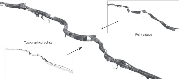
Fig. 5 3D view of the point clouds with georeference, which produced from topographical points (left) and point clouds (right) Topographical points
Point clouds
Fig. 6 Plan of the north part of the tunnel (in scale of about 1/2500) North entrance
North tunnel
Fig. 7 Plan of the south part of the tunnel (in scale of about 1/2500) Meeting Point
Mt. Ampelos
South entrance South tunnel
of the tunnel was measured, except in the north part of the tunnel. This tunnel was too narrow from the north entrance up to 150 m to measure using the laser scanner, so that we could not survey the shape of this part. In addition, the scanning had to take place in 20 - 30 m intervals in order to measure the surface from both sides, because the tunnel surface was so extremely uneven that it was not possible to scan a long distance. A total of 65 scans were made inside the tunnel.
As a result, 48,327,750 points were measured by 3D laser scanner. 43 point clouds were combined with an accuracy of less than 10 mm. Commercial software (Polyworks) was used in order to merge the point clouds. This point clouds made it possible to reproduce 3D shape of the tunnel (Fig. 4). These point clouds were referenced with the geographical coordinates (Fig. 5). The 3D laser scanner cannot measure less than 3 meters from its standing position, because of the limitations of the instrument. Therefore there are dark blank areas (occlusions) at about 20 - 40 m intervals (Fig. 5, right).It took about two months to manipulate all the data. From the digital survey, the following nal products were produced; a) a topographical map in scale of 1/500 (DWG/DXF)(Figs 6, 7), b) a 3D TIN model (VRML), c) a section of the tunnel in 1 m intervals at a scale of 1/10 (DWG/DXF) and d) isometric drawings at a scale of 1/50 (JPG)(Figs.
8, 11).
3. Description of the tunnel
According to our new measurements, the details of the tunnel were con rmed. The total distance of the tunnel was calculated from the sum of the distances
between the base points. The longitudal distance of the tunnel is 1,043 m, which is 7 m longer than reported by the DAI (1,036m). The three- dimensional
distance of the tunnel was calculated as 1,092 m.
The tunnel and pipeline are calculated as follows. In order to exclude the staircases at the north and south entrances, the slope of the tunnel was calculated between the points of S161 (55.11 m in height) and S103 (55.89 m in height).
(55.11 m - 55.89 m) / 955.31 m ×100= - 0.082 %
This result shows that the engineer was able to dig the tunnel horizontally with an error of less than 0.1%. For this, it is supposed that the engineer had to measure and control the level very often. The ‘counter-tunnel’ construction method requires reliability so that both tunnels can meet at the same level.
There is a trench along the east side of the tunnel in which a terracotta pipeline, connected by lime mortar, was laid (Fig. 2). The trench measures ca. 3.5 m deep at the north end and ca. 8.5 m deep at the south end. Therefore, the slope of the pipeline is calculated as follows:
((55.11 m - 3.5 m) - (55.89 m - 8.5 m)) / 955.31 × 100 = 0.44 %
The pipeline inclines 0.44 % from the north to the south. This result is very close to the DAI’s measurement (0.45%). Trenches for the pipeline did not run through the entire tunnel, but at about 15 m intervals. In the rest of the tunnel, the pipeline runs underground. In addition, the trench is connected in the middle with a continuous incline, even though the tunnels themselves meet in the middle with a difference in level of ca. 65 cm. Therefore, it is believed that the tunnel and trench were not constructed at the same time, but that the trench was created after the construction of the tunnel.
The tunnel was planned as a counter-tunnel with a meeting point in the middle. The meeting point is 617 m from the north entrance in pass distance (not direct distance), so the meeting point is not exactly in the center, but 85.3 m south of it. This meeting point is 62 m north of the peak of Mt. Ampelos. Two sections of the tunnel are roofed by triangular arches consisting of two stones inclining towards each other and meeting at the top (Fig. 2). The roofed sections are 165 m in total; 153 m near the north entrance and 12 m near the south entrance. The north section is divided into two parts. The stones are ca. 60 cm in height. The roo ng was necessary near the north entrance, because this part of mountain rock was prone to landslides. At the south end of the north roofed section (at S151, about 270 m from the north entrance), a massive stone measuring ca. 80 × 60 × 120 cm was used in the tunnel wall (Fig. 2). It is not known how the Samians carried this 1.3-tonne stone inside the tunnel.
4. Managing the construction 4-1. Strategy of tunnel line
The topographical drawing made it possible to hypothesize the strategy of the tunnel construction (Figs. 6, 7). The tunnel does not turn in irregular zigzag form but makes turns gradually by following strategic directions (Fig. 8). Otherwise it might not have been possible to decide the digging direction at place.
The strategy of the tunnel would have been took a role to decide the direction, when the tunnel had to turn. It might be also required to the builder to measure the tunnel very often in interval of 20 or 30 m.
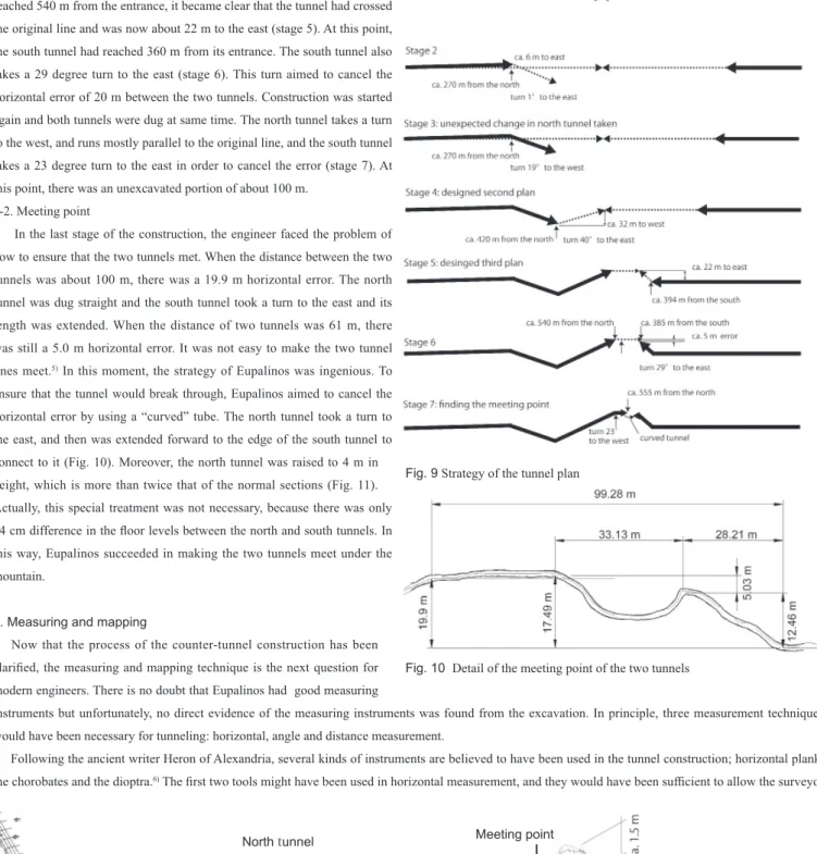
The strategy of the tunnel is summarized as follows (Fig. 9). At the beginning, both tunnels were designed as straight lines (stage 1). Soon thereafter, a small error in the north tunnel was realized. At 270 m from the north entrance, the construction line is 6 m east from original line (stage 2), and the angle error is about 1 degree to the east. Needless to say, this angle error was an important problem; however, the engineer faced a much more serious problem at that moment. Suddenly he decided to take a 19 degree turn to the west (stage 3). This unexpected change was probably caused by a geological problem. In fact, according to a geologist of our mission, there is risk of rockslides in the north part of the tunnel even now. At 280 m from the north, a section of the tunnel is stuffed with mud and partly closed. Around this part, natural water is continuously dripping from the roof of the tunnel.
The tunnel line shows it going to the west 420 m up from north entrance, passing through the original line. When the tunnel was dug up to this point, the north tunnel was 32 m west from the original line (stage 4). The south tunnel did not have any problem in its direction and probably had also been dug to about 250 m from the south entrance. At this moment, the engineer decided to change the direction of the north tunnel again in order for the two tunnels to meet. The two tunnels had to have been carefully measured, and the engineer would have had to check his drawings. Otherwise, it would not have been possible to decide the new direction.
Fig. 8 Isometric view of the north tunnel; presumed strategic line of tunneling at the turning point of stage 4 (see Fig. 9)
North tunnel Digging direction
Base point for our measurment
Hypothetical line of direction
Here again, the north tunnel takes a 40 degree turn to the east and was dug straight to 540 m from the north entrance. When the north tunnel had reached 540 m from the entrance, it became clear that the tunnel had crossed the original line and was now about 22 m to the east (stage 5). At this point, the south tunnel had reached 360 m from its entrance. The south tunnel also takes a 29 degree turn to the east (stage 6). This turn aimed to cancel the horizontal error of 20 m between the two tunnels. Construction was started again and both tunnels were dug at same time. The north tunnel takes a turn to the west, and runs mostly parallel to the original line, and the south tunnel takes a 23 degree turn to the east in order to cancel the error (stage 7). At this point, there was an unexcavated portion of about 100 m.
4-2. Meeting point
In the last stage of the construction, the engineer faced the problem of how to ensure that the two tunnels met. When the distance between the two tunnels was about 100 m, there was a 19.9 m horizontal error. The north tunnel was dug straight and the south tunnel took a turn to the east and its length was extended. When the distance of two tunnels was 61 m, there was still a 5.0 m horizontal error. It was not easy to make the two tunnel lines meet.
5)In this moment, the strategy of Eupalinos was ingenious. To ensure that the tunnel would break through, Eupalinos aimed to cancel the horizontal error by using a “curved” tube. The north tunnel took a turn to the east, and then was extended forward to the edge of the south tunnel to connect to it (Fig. 10). Moreover, the north tunnel was raised to 4 m in height, which is more than twice that of the normal sections (Fig. 11).
Actually, this special treatment was not necessary, because there was only 64 cm difference in the oor levels between the north and south tunnels. In this way, Eupalinos succeeded in making the two tunnels meet under the mountain.
5. Measuring and mapping
Now that the process of the counter-tunnel construction has been clari ed, the measuring and mapping technique is the next question for modern engineers. There is no doubt that Eupalinos had good measuring
instruments but unfortunately, no direct evidence of the measuring instruments was found from the excavation. In principle, three measurement techniques would have been necessary for tunneling: horizontal, angle and distance measurement.
Following the ancient writer Heron of Alexandria, several kinds of instruments are believed to have been used in the tunnel construction; horizontal plank, the chorobates and the dioptra.
6)The rst two tools might have been used in horizontal measurement, and they would have been suf cient to allow the surveyor
Fig. 10 Detail of the meeting point of the two tunnels Fig. 9 Strategy of the tunnel plan
Fig. 11 Isometric drawing of the meeting point
South tunnel
North tunnel Meeting point
Trench for the pipeline
to measure the outside of the tunnel; however, it would not have been possible to measure the angle-distance inside the tunnel. The third tool, the dioptra, was a sighting tube or, alternatively, a rod with sights at both ends, which was probably attached to a stand. If tted with protractors, it could be used to measure angles. The dioptra would have been able to measure the angle, so it would not have been suf cient for the actual work of tunnel measuring.
In the case of the tunnel of Eupalinos, how was the actual measuring work done? Since the inner surface of the tunnel meandered, it is necessary to measure both the horizontal level and the angle at the same time. A dioptra is able to measure vertical angles, but not horizontal angles. Since the two tunnels were designed to meet horizontally in the middle, it is natural that the builders would have to pay more attention to the horizontal angle than the vertical angle.
In addition, mapping was extremely important for checking the present location and deciding the digging direction. We may imagine the existence of an instrument which consists of a drawing tablet and a horizontal angle; however, since this kind of instrument has not been discovered, it might be better to leave this question open.
6. Conclusion
From our new survey, the details of the tunnel have been con rmed. The measurement of the tunnel shows that a high quality of leveling was done during the construction work. It is also revealed how the Greek engineers managed the tunnel construction by using continuous measurement and reassessment in every phase of the construction process. The angle and distance measurements were extremely important in the strategy of the tunneling. The correcting turns lead the two tunnels to meet in the middle, even though there were several unexpected errors. The following points are realized in this study:
1) The author presents here new measurements of high accuracy. The total length of the tunnel is measured as 1,043 m, which is 7 m longer than the DAI’s measurement. The inclination of the tunnel is calculated as -0.082 %. These measurements show that ancient engineers were skilled enough at measuring that they could construct a long tunnel with error of less than 0.1 %. The slope of the pipeline was calculated as 0.44 %.
2) The strategy of tunnel construction and its accompanying process are elucidated in this study. It is realized that there were seven stages of construction. The tunnel was designed as a straight line in the rst stage, and then, the tunnel deviates from the line because of a geological problem. The engineers would have had to measure the tunnel line at intervals of about 20 or 30 m to follow the expected line.
3) Detailed drawings and measurements present not only the dif culty of the construction of the tunnel, but also the engineers’ ingenious strategy. Especially, at the meeting point, a “curved” tube was used. The north tunnel took a turn to the east, and was then extended forward to the edge of the south tunnel to connect to it. Here again, the measurement and drawing work must have taken place. The management of the construction in the last stage is clari ed in this study.
4) The known ancient measuring instruments are not suf cient for the actual measuring work needed for this project. It would have required a horizontal angle measure and drawing table at the same time. This kind of instrument has not yet been discovered.
Acknowledgments
I would like to show my gratitude to the Ministry of Culture for their kind permission to undertake this research. I would like to thank Egnatia Odos S.A., which supported this project in full, for allowing us to publish the results. Prof. Dr. Konstantinos Tokmakidis, Aristotle University of Thessaloniki, was my supervisor when I studied in Greece. I would like to express my gratitude for his kind invitation to join this project and his approval for the use of the survey data. Finally, I would like to thank Panagiotis Tokmakidis for his contribution to the project as a surveyor.
List of the Figures
Fig. 1: Additional drawing by the author on the topographical map of Ministry of Development
Fig. 2: Additional drawing by the author on Kienast H. J., The Aqueduct of Eupalinos on Samos, Athens, 2005, Fig. 21 Fig. 3: Photo by Tokmakidis K.
Fig. 4: Tokmakidis P.
Fig. 5: Tokmakidis P.
Fig. 6, 7: Tunnel plan by Tokmakidis P., which refereced to the topographical map
Fig. 8, 11: Additional drawing by the author on the drawing by Zabas K., leader of the architectural mission Fig. 9, 10: The author
Notes
1) Grewe K., “Tunnels and Canals,” in J. P. Oleson ed., The Oxford Handbook of Engineering and Technology in the Classical World, Oxford, 2008, pp. 319-226.
2) See also Yoshitake, R., “Studies of Ancient Mediterranean Cities (131): The Ancient Aqueduct of Eupalinos on Samos,” AIJ Kyushu Chapter Architectural Research Meeting (Planning), Vol. 49-3, 2010, pp. 597-600; Tokmakidis, K., “Surveying the Eupalinian Aqueduct in Samos Island,” 22nd CIPA Symposium, CD-ROM Edition, 2009. The survey was carried out from 22 April to 5 May 2009 in Samos.
3) Kienast H. J., Die Wasserleitung des Eupalinos auf Samos, Samos band XIX, 1995.
4) Kienast H. J., The Aqueduct of Eupalinos on Samos, Athens, 2005, p. 19-20.
5) Kienast suggests that Eupalinos provided the solution by creating an angled front at the end of the north tunnel, at which the other tunnel had to arrive. It is hard to believe that Eupalinos designed such a function from the beginning. It is not easy to expect how the two tunnels will be, before starting the construction. It might be fair to consider that Eupalinos was good enough at practical construction that he could expect that it might not be possible to construct the tunnel straight, and he knew he would have to manage the construction while monitoring the situation. Kienast H. J., Die Wasserleitung des Eupalinos auf Samos, Samos band XIX, 1995, p. 168.
6) Kienast, op.cit., p. 187.
����
���� ��� ������������������������
������������������������������
��������������� � ��������������
������������������������������
������������������������������
����������������� ��������������
������������������������������
�����������������������������
���� ����������������������������
������������������������������
������������������������������
�������
������������������������������
������������������������� � ����
������������������������������
������������������������������
������������������������������
���� ����� �����������������������
���������� ����������������������
�������������������
��������� � ���������������������
��������������������������� ��� �
��� ����������������������������
��������������������������������
������������������������������
������
������������������������������
������������������������������
������ ������������������������
������������������������������
������������������������������
������������������������������
���� ��� ��� � �������������� ��� �����
������������������������������
��� ���� ��������������
������������������������������
������������������������������
������������������������������
������������������������������
������������������������������
������������������������������
�������
������������������������������
�������� ��� ��������������������
���������������������������� ���
������������������������������
������������������������������
������������������������������
������������������������������
������������������������������
����
(2011年7月1日原稿受理,2011年11月21日採用決定)