Terrain Representation Methods in VR Environment
Koji Makanae
Miyagi University
1 Gakuen, Taiwa, Miyagi, Japan [email protected]
Morio Nakahara
Graduate student, University of Tsukuba Tsukuba, Ibaraki, Japan
[email protected]
Abstract
This paper describes methods for visual 3D representation using VR technology and introduces the terrain rep- resentation methods that the authors have developed and some of the application systems using those methods.
Furthermore the tangible terrain representation system which has been worked on is shown against the prob- lems of conventional methods. The paper also discusses possibilities of further development of terrain repre- sentation systems, positioning 3D terrain representation systems.
Keywords
Terrain representation, Tangible display, Virtual Reality, DEM, VR-CAD
1. INTRODUCTION
Recent advances in the development and dissemination of spatial information have made it possible to obtain and use various types of spatial information easily. It is also becoming possible to obtain and use topographic infor- mation on a global scale. Topographic information is in many cases provided in the form of mesh data such as USGS Digital Elevation Models (DEM) . Such informa- tion may be provided by, for example, representing dif- ferent elevations and slopes with different colors, gener- ating contours from mesh data, generating shaded-relief maps automatically or using bird's-eye views prepared by projection transformation for 3D representation. These methods, however, represent terrains in two dimensions on the computer display, instead of as three-dimensional objects as in the real world. These representation meth- ods, therefore, make it difficult to understand topog- raphic relief intuitively. To solve this problem, the au- thors have been working on the research and develop- ment of methods for representing virtual terrain surfaces defined on the computer by applying virtual reality (VR) technology and of systems that can be realized by apply- ing those methods.
This paper describes methods for visual 3D representa- tion using VR technology and introduces the terrain rep- resentation methods that the authors have developed and some of the application systems using those methods.
The paper also discusses possibilities of further devel- opment of terrain representation systems, positioning 3D terrain representation systems.
2. VR-BASED VISUAL 3D REPRESENTATION METHOD
Virtual reality (VR) is a technology to experience a real- istic virtual world defined on the computer. The technol- ogy uses an interface making effective use of stereo- scopic visualization made possible by means of the two
human eyes in order to visually enhance the degree of reality.
The mechanism by which a human visually recognizes the three-dimensional configuration of an object involves two types factors: physiological factors and psychologi- cal factors. Physiological factors, which are due to the functions of the human eye, include the focus adjustment function of the lens, eye convergence, binocular parallax and monocular motion parallax. Psychological factors, which help reconstruct 3D images from experience, are classified either as geometric or optical. Among these factors, binocular parallax, which is one of the physio- logical factors, is generally thought to be most important in 3D perception.
The stereoscopic visualization technology used in the field of virtual reality is based mainly on 3D perception caused by binocular parallax. If the locations of the eyes of a human viewer are determined in a virtual space de- fined on the computer, a pair of perspective images just like images that would be perceived by the two human eyes can be obtained by applying computer graphics (CG) technology. By giving the perspective images thus obtained to the two eyes of a human viewer, the viewer can be made to perceive the images as a 3D object. De- vices for giving different images to the left and right hu- man eyes have been developed during the evolution of virtual reality technology. Representative examples of such devices are stereoscopic eyeglasses with liquid crys- tal shutters, 3D displays, head-mounted displays (HMD) and immersive displays.
1. Stereoscopic eyeglasses with liquid crystal shutters
A stereoscopic eyeglasses system with crystal liquid
shutters provides different images to the left and right
eyes by displaying images for the left and right eyes
alternately at high speed on a single CRT display and
synchronizing those images with the liquid crystal shutters of the stereoscopic glasses. Because the dis- play area is fixed on the display system, the user is not allowed to move around.
2. 3D display system:
A 3D display makes it possible to have stereoscopic views with the naked eye by using binocular parallax and eye convergence. Like the stereoscopic eye- glasses method, this method does not allow the user to move around. Recent advances in technology, however, have been rapidly making inexpensive sys- tems available on the market.
3. 3D display system:
A 3D display makes it possible to have stereoscopic views with the naked eye by using binocular parallax and eye convergence. Like the stereoscopic eye- glasses method, this method does not allow the user to move around. Recent advances in technology, however, have been rapidly making inexpensive sys- tems available on the market.
4. 3D display system
A representative example of an immersive display system is an IPT (immersive projection technology) device called the "CAVE" (Cave Automatic Virtual Environment) developed by the University of Illinois [Cruz93]. In the CAVE, 3D images can be projected onto about 3m by 3m screens placed at the left and right and at the front of the user and on the floor so that the user can immerse herself or himself into the 3D visualization environment. The CAVE is advanta- geous because it provides a wider field of view than the HMD and does not require image generation syn- chronized with movement, so problems such as a de- lay in image generation do not occur.
In recent years, research and development efforts associ- ated with mixed reality, which aims to integrate virtual space and real space have also been underway. One of these efforts is the research and development of tangible interface. The MIT Media Laboratory, for example, has developed a system called "Illuminated Clay," which projects information onto a terrain surface created with clay [Piper02].
3. TERRAIN REPRESENTATION AND DESIGN SUPPORT SYSTEMS DEVELOPED TO DATE The authors have been working to develop terrain repre- sentation methods making use of VR technology and construct design support systems using these methods.
This paper describes (1) a road design support system that uses stereoscopic visualization of aerial photographs and (2) a terrain representation and urban space modeling system that uses an HMD, both of which have been de- veloped by the authors, along with problems of these systems.
3.1 Highway Route Planning System Using Stereoscopic Visualization of Aerial Photo- graphs
Makanae[Makanae02] has developed a system (HRPS;
Highway Route Planning System) that acquires terrain images through the stereoscopic visualization of aerial photographs and enables road design. Aerial photograph images taken into the computer in the form of digital information are shown on the display of a stereoscopic viewer (CrystalEyes2 manufactured by Stereo Graphics, Inc.) as information that can be visualized stereoscopi- cally (Figure 1). A coordinate system identical to the stereoscopic visualization space obtained by aerial pho- tograph orientation is defined on the computer, and road design is conducted in this 3D virtual space. Parametric curves (B-spline) are used to define road alignments, and control points are located within the space so that their alignments can be defined easily.
Figure 2 shows the interface of the system. A 3D model of each road structure is automatically generated accord- ing to the alignment defined on the aerial photograph, and plans, longitudinal profiles and perspectives can be displayed.
An advantage of this system is that it allows an engineer who is good at interpreting topographic characteristics (e.g., landslides) from aerial photographs to directly de- termine road alignments with the assistance of a road design module that uses parametric curves. This is par- ticularly advantageous in, for example, designing moun- tain roads under poor topographic conditions. By making direct use of aerial photographs, unnecessary mapping processes can be eliminated. A problem with this system is the applicability of road alignments determined by using parametric curves to the current design standard.
Another problem is that the relationship between con- Figure 1 The configuration of HRPS
Figure 2 Interface of HRPS
structed road structures and the terrain surface repre- sented in a virtual 3D visualization space cannot be com- puted.
3.2 Terrain representation method using HMD:
VR-CAD system
In the conventional drawing-based space design method, the designer constructs 3D configurations in his or her mind while preparing drawings. VR technology, however, makes it possible to define any 3D virtual space on the computer. The VR-CAD system developed by Makanae [Makanae03] enables the designer to immerse himself or herself into a virtual space constructed on the computer.
In the virtual space, the designer can exist on any scale:
the designer can enter the space either as a correctly scaled human figure or as a giant. The system also en- ables the designer to conduct 3D design without relying on the 2D/3D conversion capability of the designer.
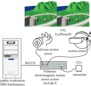
The system consists of a head-mounted display (HMD) and 3D position sensors (Figure 3). By combining the HMD and a position sensor, the position and orientation of the head can be measured and appropriate images can be displayed so that the design has a 360-degree field of view both in the horizontal direction and in the vertical direction.
Since the system is intended for use in constructing large structures such as roads, terrain information is essential.
Elevation data (50 m mesh) in Digital National Land In- formation are used as 3D terrain models for terrain repre- sentation in the virtual space. The modeling input inter- face of the VR-CAD system has a 3D mouse and key- board equipped with a position sensor. These devices enable 3D modeling of such features as buildings (rec- tangular prisms, cylinders), roads and trees by simple operations. Known problems of the design interface of this system include the difficulty in perceiving the posi- tion of the 3D cursor and the difficulty in comprehending the relative positions of the terrain surface and the object of interest [Makanae03].
4. DEVELOPMENT OF TANGIBLE TERRAIN REPRESENTATION SYSTEM
Problems of the terrain representation and design support systems include the following:
Difficulty in comprehending the relative positions of the terrain surface and the object of interest
Need for a special stereoscopic visualization device
Limited field of view
Not usable for group work
Believing that the introduction of a tangible interface helps solve these problems, the authors have been work- ing on the construction of a tangible terrain representa- tion system.
Figure 4 shows the configuration of the terrain represen- tation system. As shown, the system represents a terrain surface by controlling the shape of a stretchable screen used to represent the terrain surface by means of a total
of 64 actuators (8×8) and projecting an aerial photograph onto the screen. Mesh data of Digital National Land In- formation(Japan) are used as terrain data, and the height of each actuator is determined according to the mesh data values.
Figure 5 shows an example of a terrain represented by using the system. The terrain model onto which an aerial photograph is projected is a touchable terrain model. As the next steps, the authors are thinking of evaluating the validity of the terrain representation system and con- structing design support systems for roads and other structures by adapting the existing system.
5. OUTLOOK FOR TERRAIN REPRESENTATION SYSTEMS
The ongoing development and dissemination of spatial information are making it increasingly easier to obtain and use digital terrain information. Obtained terrain in- formation, however, can only be displayed in a limited area of a flat display device. Consequently, it is difficult to give the viewer a sense of three-dimensionality and a sense of scale. The authors have been working on the development of the systems described in Sections 3 and 4.
Requirements for a terrain representation system identi- fied in view of the problems encountered in connection with the development of those systems are as follows:
1. Recognition of the three-dimensionality of terrain surfaces is easy.
2.. The user does not need to wear any special device such as stereoscopic glasses or HMDs.
3. Reconstructed terrain surfaces can be matched with digital information.
4. Various types of information can be superimposed.
The first requirement is one of the basic requirements for a terrain representation system, so it is necessary to make a higher degree of three-dimensional recognition possible.
The second requirement is listed here because the use of
Figure 3 The configuration of VR-CAD
special equipment may cause fatigue or sickness, making many hours of use difficult. The use of special equipment should be avoided as much as possible. The third re- quirement is important because in order to develop an application system, it is necessary to extract a particular point on a virtual terrain surface in digital form. The fourth requirement is also important because the terrain representation system can be used effectively by super- imposing not only aerial photographs but also other data such as land use data and city plans on the reconstructed terrain surface.
Examination of these requirements indicates that the fol- lowing systems are thought to be promising in the com- ing years:
1. Tangible terrain representation system
The tangible terrain representation system that the au- thors are currently developing can satisfy all of the four requirements listed above. The system, however, is still at the development stage, and it is necessary to further enhance the resolution of terrain representation and de- velop equipment and devices that can be easily used even by non-expert users. It is also necessary to develop a pointing device for use on a virtual terrain.
2. Terrain representation system using rapid prototyping Recent advances in CAD/CAM technology has made possible fast advances in rapid prototyping technology to make real 3D models from resin or other materials in accordance with 3D data prepared as CAD data. In recent years, this technology has been increasingly used to make terrain models more easily than by other methods. Prob- lems of terrain representation systems of this type include the difficulty in getting feedback from completed terrain models to electronic information and the necessity of the development of pointing devices as in the case of tangi- ble terrain representation systems described above 1.
3. Terrain representation system with 3D display
A 3D display enables the user to have three-dimensional recognition without using special equipment. A terrain representation system with a 3D display is being devel- oped and used at the authors' laboratory, and the system has proved effective in giving a strong sense of three- dimensionality. The system satisfies the first, second and fourth requirements mentioned above although the de- gree of strength varies among individuals. A problem of
this system concerns the matching of the virtual terrain surface and digital terrain information (related to the third requirement mentioned above), so it is difficult to indicate a particular point on the terrain surface accu- rately.
6. CONCLUSION
This paper has introduced a number of methods for re- constructing terrains from digital terrain information that the authors have developed, and application systems us- ing the terrain representation methods. The paper has also identified requirements for a terrain representation system to be used as a GIS tool and has described terrain representation systems that are likely to prove useful in the coming years.
At present, the representation of digital terrain informa- tion is restricted by 2D display devices. With further ad- vances in representation and control technology made possible by the progress of VR technology and robotics, however, more realistic and easier 3D terrain representa- tion will become possible. The authors believe that ad- vances in terrain representation technology can contrib- ute to not only research in the fields of technology and science such as geography, geology and civil engineering but also CAD interfacing in the field of construction, and also to a wide range of other applications such as geo- graphic education.
7. REFERENCES
[Cruz93] C. Cruz-Neira, D.J.Sandin, Defanti, T.A. Sur- roud-Screen Projection-Based Virtual Reality: The Design and Implementation of the CAVE. Proceed- ings of SIGGRAPH’93, 135-142, 1993.
[Makanae02]K. Makanae. Stereoscopic Systems for 3-D Highway Route Planning on Aerial Photo-graphs, In- ternational Journal of Design Sciences & Technology, Vol.9-1, 15-22. Europia Productions, 2002.
[Makanae03]K.Makanae. Development of the VR-CAD System for Landscape and Town Planning. Proceed- ings of the CONVR2003, Virginia Tech, 114-121, 2003.
[Piper02]B.Piper, C.Ratti, H.Ishii. Illuminating Clay: A 3-D tangible interface for landscape analysis. In Pro- ceedings of the Conference on Human Factors in Computing Systems (CHI’02) 20–25 April, Minnea- polis, 2002.
ABCDEFGH
SELECTED ON-LINE