九州大学学術情報リポジトリ
Kyushu University Institutional Repository
親水・撥水混合伝熱面を用いたループ型サーモサイ フォンに関する研究
何, 洪斌
https://doi.org/10.15017/1866297
出版情報:Kyushu University, 2017, 博士(工学), 課程博士 バージョン:
権利関係:
Study on a Mixed-wettability Evaporator Surface of a Loop Thermosyphon
Ph.D. Thesis Hongbin He
Department of Mechanical Engineering Graduate School of Engineering
Kyushu University Japan
July 2017
i
Contents
Nomenclature vi
Chapter 1 Introduction 1
1.1 Introduction 1
1.1.1 Background 1
1.1.2 Literature review 2
1.2 Heat pipe technologies 3
1.2.1 Conventional heat pipes 3
1.2.2 Loop heat pipes 5
1.2.3 Pulsating heat pipes 6
1.2.4 Conventional thermosyphons 7
1.2.5 Loop thermosyphons 9
1.3 Influence factors of heat pipes 11
1.3.1 Boiling at sub-atmospheric pressure 11
ii
1.3.2 Working fluids 14
1.3.3 Surface with enhanced structure 16
1.3.4 Surface wettability 17
1.4 Development of heat pipe models 19
1.5 Thesis objective 21
1.6 Thesis outline 22
Chapter 2 Experimental apparatus and measurement procedure 24
2.1 Experimental apparatus 24
2.1.1 Schematics of a loop thermosyphon 24
2.1.2 Apparatus of a loop thermosyphon 24
2.1.3 Mixed-wettability evaporator surfaces 28
2.2 Experimental procedure 29
2.2.1 Leakage check 29
2.2.2 Operating principle 29
2.3 Experimental measurement 29
iii
2.4 Data calculation analysis 31
2.5 Uncertainty of the experimental data 32
Chapter 3 Experimental study on HNTs coated surface 34
3.1 Patterned surface 34
3.2 Comparison of experimental results 35
3.2.1 Experimental results 35
3.2.2 Bubble behaviors 39
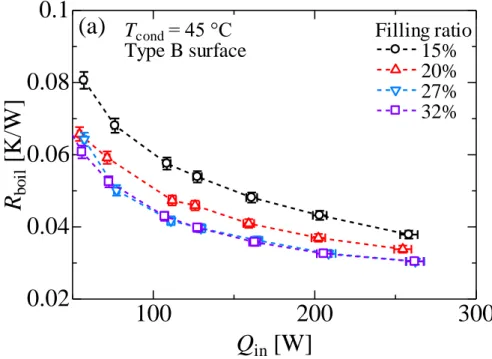
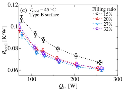
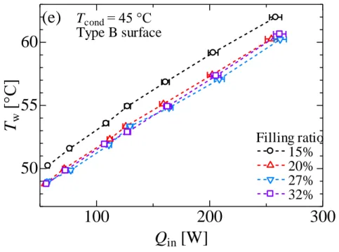
3.3 Effect of filling ratios 42
3.3.1 Height of liquid level 52
3.3.2 Experimental results 43
3.4 Effect of condenser temperatures 48
3.4.1 Experimental results 48
3.4.2 Bubble behaviors 53
3.5 Heat loss test 54
3.6 Durability test of hydrophobic spots 56
iv
3.7 Comparison between experimental results and models 57
3.8 Conclusions 59
Chapter 4 Experimental study on FDPA coated surface 60
4.1 Patterned surface 60
4.2 Comparison of experimental results 62
4.2.1 Experimental results 62
4.2.2 Bubble behaviors 65
4.3 Effect of filling ratio 67
Chapter 5 Experimental study on Ni-PTFE coated surface 71
5.1 Patterned surface 71
5.2 Experimental results of Ni-PTFE coated surface 74
5.2.1 Experimental results 74
5.2.2 Bubble behaviors 78
5.3 Development status of thermosyphons 79
v
5.4 Comparison of mixed-wettability surfaces 80
5.5 Comparison with machined surface 82
5.5.1 Machined surface 82
5.5.2 Experimental results 83
5.5.3 Bubble behaviors 85
Chapter 6 Conclusions and future work 87
6.1 Conclusions 87
6.2 Future work 90
References 92
Acknowledgements 103
Appendix 105
vi
Nomenclatures
A evaporator surface area
c
pspecific heat
C
scomprehensive effect parameter of heating surface
d diameter
FR filling ratio
h heat transfer coefficient
k thermal conductivity
la Laplace coefficient
L
lvlatent heat
m mass flow rate of condenser
Nu Nusselt number
p pitch
P pressure
ΔP pressure difference
Pr Prandtl number
q heat flux
Q heat transfer rate
R thermal resistance
Re Reynolds number
T temperature
ΔT temperature difference
x distance of two thermocouples
vii
Greek symbols
ν viscosity
σ surface tension
𝜌 density
thermal conductivity
Subscripts
amb ambient
boil boiling
cond condenser
in input
l liquid
loss heat loss
out outlet
safe safety condition
sat saturation
v vapor
w surface
Chapter 1 Introduction
1
Chapter 1 Introduction 1.1 Introduction
1.1.1 Background
In recent years, thermal management for electronic components such as CPU has become a serious problem. Heat dissipation has been increasing rapidly due to the growing trend of high performance computing [1]. It is well known that excess heat reduces the performance of these electronic chips and can ultimately destroy the delicate circuits, it will be necessary to design an effective high performance cooler for these kinds of high power electronic chips. Cooling system for high power electronic devices becomes increasingly more significant. Its role in the operation of these devices becomes critical sometimes concerning the safety, reliability, and life of the system.
Traditional forced air cooling is limited and may be insufficient to meet the high demand of future electronics [2]. More applicable and reliable technologies of heat dissipation need to be developed to meet the challenges [3, 4]. It is well known that liquid cooling is superior to air cooling due to the heat capacity and the overall thermal resistance. Liquid cooling with phase change is a very promising way for thermal management of electronics because it achieves very high heat transfer coefficient compared to single phase cooling [5].
Consequently, it is imperative to develop the high performance cooling
technologies to substitute the conventional air cooling systems. Heat pipes are widely
used in many industrial applications [6 – 11]. They enable the transfer of high heat
fluxes with low temperature gradients by using the latent heat of vaporization of a
working fluid [12]. The diversity of the different kinds of heat pipes reflects the
diversity of the conditions in which they are used. However, whatever the type of heat
pipe, their normal behaviour is bounded by several operating limits that depend on
various phenomena. Heat pipes are the object of thousands of scientific articles
published in more than a hundred international journals. Despite the numerous studies
on heat pipes for fifty years, the development of predictive tools for the design is still
challenging, even for conventional technologies. It results in a real limitation in the
Chapter 1 Introduction
2
spreading of heat pipes in the industry, as each new heat pipe has to be carefully designed for each specific application. Through a review of the recent works published on heat pipes, the author aims to understand the scientific key issues leading to this situation and to build the strategies that can be implemented to progress towards a better understanding of the different types of heat pipes.
1.1.2 Literature review
Fig. 1.1 Word cloud of the titles of articles about heat pipes [13].
During several years, the research field on heat pipes has changed substantially. Fig.
1.1 presents a word cloud realised from the titles of the articles published on heat pipes between 2012 and 2014 (about 800 papers). In this word cloud, the size of the words is proportional to the square root of the number of occurrence of each word.
Fig. 1.2 presents the distribution of the papers in the main journals. Despites the
great number of journals publishing articles on heat pipes, about 40% of the papers was
published in only 10 journals and almost all of them are dedicated to research on heat
Chapter 1 Introduction
3
transfer. However, it is found that the heat pipes also interest the communities of solar and renewable energy applications, industrial applications and electronic cooling applications.
Fig. 1.2 Distribution of the papers of the international journals on heat pipes in recent years [13].
1.2 Heat pipe technologies
1.2.1 Conventional heat pipes
Heat pipes operating with a phase change process are known as heat-transfer devices with a high efficiency [14]. In 1972, the first heat pipe was designed and tested successfully by the scientists Gerasimov and Maydanik from the Ural Polytechnical Institute in Russia. It had a wick structure with capillary pumping of a working fluid.
However, with the rapid development of sciences and technologies, heat pipes are
becoming much more popular for electronics thermal management, heat transfer,
cooling, air-conditioning and utilization of waste heat. Recent heat pipe including heat
pipe panels, conventional heat pipes, pulsating heat pipe, miniature pipes, and sorption
heat pipes were studied by many researchers [15 – 20].
Chapter 1 Introduction
4
Fig. 1.3 Schematic of a cylindrical heat pipe.
As shown in Fig. 1.3, the main parts of a loop heat pipe are the evaporator and condenser. It is a passive cooling system with the heat removal by free air fans from an external radiator. The evaporator of a loop heat pipe maybe a flat or cylindrical, which is related to the shape, the heat source, the working fluids and the designing purpose.
Conventional heat pipes have sintered wick structure inside as a convenient heat transfer devices [21]. It has a very excellent ability to transport a large amount of energy through long distance with a low temperature difference. The liquid is vaporized at the evaporator chamber, and vapor is condensed at the heat sink [22, 23].
Some of the advantages of the application of a loop heat pipe in electronic devices
cooling system are summarized by Maydanik et al. as: 1) a much higher capacity at
comparable dimensions; 2) operating at any orientation in the gravity field; 3) a
considerable and low thermal resistance; 4) flexibility in packaging; 5) high heat flux
over a considerable distance, and so on [24]. There were many research works on loop
heat pipe for cooling electronic devices. V.G. Pastukhov et al. investigated an active
cooler for CPU of desktop computers on the basis of copper-water loop heat pipes with
the minimum value of total thermal resistance of 0.15 K/W. Heat transfer capacity of
the cooler was 500
600W [25]. Ji Li et al. reported a copper-water compact loop heat
Chapter 1 Introduction
5
pipe with a flat square evaporator with a thermal resistance as low as 0.042 K/W at the heat load of 628 W [26]. The significant contributions regarding to the improvement of the new capillary evaporator design was presented by Roger R. et al. They designed the capillary evaporator primary wick with circumferential grooves, which gave the lower evaporator temperature and high efficiency to collect the vapor [27].
1.2.2 Loop heat pipes
For loop heat pipes (LHPs), the sum of frictional and gravitational pressure drops are compensated by the capillary forces in the capillary structure placed at the evaporator only, as seen from Fig. 1.4.
Fig. 1.4 Loop heat pipe.
It is developed from the conventional heat pipe. In a loop heat pipe, it consists of an
evaporator, a condenser, a vapor line, a liquid line and a hydro-accumulator [28]. The
heat flux dissipated at the evaporator outer wall is transferred to the wetted porous wick
structure in the evaporator inner wall. The main part of the heat flux is consumed in the
evaporation process at the porous wick surface, while the other part of the heat flux is
Chapter 1 Introduction
6
transferred by the reservoir through the porous wick [29]. A slight pressure-head between the evaporator channels and the reservoir is induced by the vapor production in the evaporator channels. This slight pressure difference forces the vapor to flow in direction to the reservoir through the smooth transport lines. Thus, the heat flux dissipated by the heat source is efficiently transported by the vapor flow from the evaporator to the condenser heat exchanger. The heat flux is released to the heat exchanger involving the latent heat of condensation, as the vapor flow returns into the liquid state when in contact to the cold surface of the condenser. The loop heat pipe operation is then self-regulated in temperature according to the net heat balance in the reservoir. The evaporation process at the porous wick surface in contact to the evaporator channel generates liquid/vapor menisci in the porous wick. Such menisci induce a capillary force, which insures the liquid flow through the porous wick from the reservoir to the evaporation interface without any active pump [30]. The fluid loop is completed.
1.2.3 Pulsating heat pipes
Pulsating heat pipes (PHPs) are made of a single meandering tube placed between the heat source and the heat sink, which is developed in 1990. The diameter of the pipes, close to the fluid capillary length, leads to a distribution of the fluid within the tube into liquid plugs and vapor slugs. As shown in Fig. 1.5, it is a simple het pipe without wick structure relying on the motion of phase change [31]. A typical pulsating heat pipe is partially filled with the working fluid [32]. The violent vaporization of multiple liquid slugs in the evaporator, associated to the condensation of multiple vapor plugs at the condenser, generates self-sustained oscillations of the fluid [33]. It leads to an efficient heat transfer from the heat source to the heat sink, both by latent and sensible heat [31].
These systems are cheap and easy to manufacture, but their behaviour is difficult to
predict and they are currently sparsely used in the industry. Vadim Tsoi et al. studied a
plate-type thermosyphon with the inter-connected multi channels in the evaporation
section, which is considered as a pulsating thermosyphon leading the the better thermal
resistance [34].
Chapter 1 Introduction
7
Fig. 1.5 Pulsating heat pipe.
However, at the present stage, the life time of the liquid pump and the possible leakage during the operation are two critical concerns to limit the commercial promotion of this technology in industry. In addition, the capillary structure of a loop heat pipe and its installation in the electronic equipment are very complicated and much more expensive compared to other conventional solutions. Other cooling system must be designed, which need to have the simple structure and high efficiency.
1.2.4 Conventional thermosyphons
As an effective and reliable heat removal technique, a loop thermosyphon (gravity
assisted heat pipes), which has a simple structure and high heat transfer coefficient, is
studied by many researchers. A large amount of heat is transferred by small temperature
differences between the evaporator and condenser [35, 36]. Both the pressure head due
to vapor generation and the large density ratio of liquid to vapor drive the coolant flow
Chapter 1 Introduction
8
[37, 38]. It is a reliable gravity-assisted wickless heat pipe. This feature can result in a convenient operation without wick structure and better heat transfer performance compared with conventional heat pipes [39, 40]. Vapor is condensed and changed into liquid flowing to the evaporator by gravity [41]. Thermosyphons may be separated into two kinds of shapes, conventional thermosyphons and loop thermosyphons [42]. The schematic of a thermosyphon is presented in Fig. 1.6. The conventional thermosyphon includes a cylinder vacuum pipe, which is filled with the working fluid partially [43, 44].
The liquid in the evaporation zone starts boiling with the supplied heat source. Then the vapor generated goes through into the condenser part where it condenses [45]. The heat goes out through the condenser wall to the external heat sink [46]. There is a counter- current between the movement of the liquid and vapor.
H. Jouhara et al. proposed an experimental investigation regarding to a smaller
diameter (6 mm) copper thermosyphon for providing the heat dissipation 30 – 50 W
approximately [47]. Y.J. Park et al. investigated a closed thermosyphon with various
filling ratios, which was performed in the range of 50 – 600 W heating powers. The
grooved surface improved the heat flux compared with those of smooth surface due to
the excellent bubble nucleation on grooved surface [48]. The cryogenic thermosyphon
under different cooling conditions and various filling ratios was designed by Z.Q. Long
et al. They experimentally analysed the results to understand the mechanisms of heat
transfer limit for various operating conditions [49]. X.F. Yang et al. investigated a loop
thermosyphon using functionalized nanofluid (silica nanoparticles) as the working fluid
to keep the long-term stability of the heat transfer performance owing to the covalent
bonding Si-O-Si. Under three different operating pressures, the wall temperatures were
very low with functionalized nanofluid compared with the water [50].
Chapter 1 Introduction
9
Fig. 1.6 Schematic of a conventional thermosyphon.
1.2.5 Loop thermosyphons
The closed two-phase loop thermosyphon is an attractive cooling system and
widely used in various engineering application as a cooling system [51]. This apparatus
has two pipes to connect two heat sources where heat is going from the hot source to the
cold source by a long distance [52]. For the conventional thermosyphons, the vapor
moves upward from the evaporation zone, where the pressure is high, then into the
condenser, where the pressure is low. This phenomenon causes a limited heat transfer
capacity due to the extra hydrodynamic resistance. This resistance increases with an
increase of the heating power.
Chapter 1 Introduction
10
Fig. 1.7 Schematic of a two-phase loop thermosyphon.
The mentioned issue would be solved by the design in Fig. 1.7, which was
proposed by Kapitanchuk et al. firstly in 1967 [53]. Lots of studies about this kind of
thermosyphon have been carried out during the past few decades owing to the cost-
effectiveness, high efficiency, and reliability [54]. The advantage is that it is easy to use
the flexible pipes connecting the boiling and condenser chambers [55]. The condenser is
arranged over the evaporator [56]. This kind of loop thermosyphon is capable of
transferring heat with high heat flux over a very long distance, and maintaining an
excellent temperature. Because the vapor flow and the liquid flow are separated, the
counter flow is avoided [57, 58]. It is found to be an effective way to recover heat and
utilize free energy. The critical heat flux is 1.2 – 1.5 times higher than those of the heat
pipes with a wick structure [59]. H. Louahlia-Gualous et al. designed a loop
thermosyphon with a micro-porous layer of the evaporator to cool electronic devices
using water as the working fluid [60]. S.W. Chang et al. carried out a developed loop
thermosyphon with series of experimental tests. The thermal network and
thermodynamic cycle of the thermosyphon loop were analysed [61]. Ji Li et al.
Chapter 1 Introduction
11
proposed a unique insert-type closed thermosyphon working for a solar water heater, which had twice heating speed compared with the conventional one. It was a developed thermosyphon without any temperature overshooting, which got to a steady operating situation quickly [62]. P. Zhang et al. established an experimental setup about a loop thermosyphon and measured the flowing features, including the effect of different heights and temperatures. The results showed that the large temperature difference raised the liquid head and the results got better [63]. The overall transient performance was also by the researchers in the past years. The thermosyphon with water as the working fluid was analysed with emphasis on the dynamic behaviour and mass fluxes under the transient condition [64].
1.3 Influence factors of heat pipes
1.3.1 Boiling at sub-atmospheric pressure
Boiling, due to the large latent heat of vaporization, is a highly efficient means of energy transfer and therefore has a wide range of industrial applications as varied as water-cooled nuclear reactors, fossil fuel power plants, heat pipes and microchannels for electronics cooling, and chemical processes. In the case of pool boiling, where the heating surface is immersed in a large body of stagnant liquid, individual vapor bubbles emerge from distinct nucleation sites and ultimately grow detached from the heating evaporator surface owing to the buoyancy effect. The efficacy of boiling heat transfer is characterized by two important parameters, the heat transfer coefficient (HTC) and the critical heat flux (CHF).
As a typical boiling curve shows (Fig. 1.8), the boiling heat transfer involves
processes of natural convection, nucleate boiling, transition boiling, and film boiling. In
region I, heat is removed by natural convection from the surface to the liquid. When the
wall superheat becomes sufficient to cause vapor nucleation at the heating evaporator
surface, it is the nucleate boiling, region II-III, in Fig. 1.9. The first bubble nucleation is
called the point of onset of nucleate boiling (ONB).
Chapter 1 Introduction
12
Fig. 1.8 The representative boiling curve of heat flux vs wall superheat.
Fig. 1.9 Nucleate boiling, copper/water, T
sat= 15 K, q = 250 kW/m
2K.
The critical heat flux on the peak point marks the upper limit of nucleate boiling
where the interaction of the liquid and vapor streams causes a restriction of the liquid
supply to the heating surface. The transition boiling region is characterized by the
Chapter 1 Introduction
13
existence of an unstable vapor blanket over the heating surface. Intermittent wetting of the surface is believed to occur. The film boiling is a phenomenon with a stable vapor film covers the entire heating surface as shown in Fig. 1.10. Heat transfer is accomplished by conduction and convection through the vapor film as the increasing surface temperature.
Fig. 1.10 Film boiling, PTFE/water, T
sat= 59 K, q = 25 kW/m
2K [65].
Aiming at the thermal management of the electronic devices, boiling heat transfer seems to be an advanced way to meet the requirement of heat dissipation. Due to the high heat transfer coefficient and heat flux in the process of the nucleate boiling, we focus on utilizing and enhance the function of this process. The boiling performance of water at low pressures decreases significantly compared to that of water at the atmospheric pressure. Research on the boiling of liquids at sub-atmospheric pressures has mainly focused on the effects of reduced pressures on the bubble nucleation process, critical heat flux, incipient superheat and surface temperature.
Hence, how to reduce the negative effects of reduced pressures on the bubble
nucleation process needs to be considered. At sub-atmospheric pressures, both the
bubble departure time and radius increase substantially [66], and result in a decreased
Chapter 1 Introduction
14
heat transfer coefficient [67]. Research on the boiling at sub-atmospheric pressures has shown both the departure time and the departure radius increase obviously.
One of the early works on boiling at sub-atmospheric pressures was by Van Stralen [68], who studied boiling within a pressure range of 13.3 – 101.3 kPa. A reduction in heat transfer during boiling at sub-atmospheric pressures was found. He observed that decrease in pressure delayed the onset of nucleate boiling, led to increase in the bubble sizes, while reducing the maximum heat flux attained. He also experimentally investigated the growth rate of vapor bubbles in water using a nickel-plated copper- heating surface for a pressure range of 2 – 26.7 kPa. They observed that the bubble departure time and departure radius increased substantially with decrease in operating pressure [69]. McGillis et al. investigated the boiling of water in a thermosyphon configuration at sub-atmospheric pressures using a plain surface by expended area [70].
They observed that lower pressure generated larger nucleation bubbles, which disturbed growth of active nucleation sites, resulting in larger wall superheats. However, advanced surface improved the heat transfer with lower wall superheat and increased the critical heat flux. An experimental investigation was carried out to understand the effect of operating pressure. It was shown that the maximum heat removal and the total heat resistance of heat pipes increase generally with the increasing of the system pressure [71]. Niro et al. showed, by combining the Clausius-Clapeyron equation with the Laplace equation, the superheat necessary for bubble nucleation would decrease with increasing pressure. The average departure diameter decreases with increasing pressure. This reduction is due to the additional activation of smaller cavities at higher pressures, and smaller cavities give smaller bubbles. But for a given cavity, Slooten observed only a small reduction of the departure diameter at increasing pressure [72].
1.3.2 Working fluids
The most significant factor of thermosyphon performance is the thermal resistance, which is directly representative of heat transfer performance [73]. For years many researchers studied the factors affecting on the performance of thermosyphon [74 – 81].
One way to improve the thermal performance of thermosyphon is through changing the
Chapter 1 Introduction
15
working fluid [82, 83]. The choice of the fluid is indeed of a great importance and it is not so difficult to choose an appropriate fluid for the appropriate heat pipe technology for a specific application. The fluid properties must show a good trade-off between high latent heat of vaporisation, surface tension and thermal conductivity and a low viscosity for the whole range of operating temperatures. A given operating temperature corresponds to a given operating pressure that the heat pipe must be able to withstand.
Other criteria, like toxicity for the humans and the environment must also be taken into account. As an example, water can be an appropriate working fluid for an operating temperature range from 50 °C to 150 °C, but problems of low pressure and high pressure can occur out of this range. Moreover, freezing can also be a problem for heat pipes with certain kinds of capillary structures. Studies on new fluids are thus necessary [84].
It is well known that mixing fluid with nanoparticles results in deposition of a nanoparticle layer on the surface and then changes both the surface wettability and roughness. According to the experimental results proposed by Liu et al. that carbon- nanotube suspensions can evidently strengthen the heat transfer coefficient, which has more than doubled compared with water under the low operating pressure [83]. Kamyar et al. added TiSiO
4nanopaticles to water and applied those to a closed thermosyphon [81]. At the heat load of 40 W and 0.05% volume concentration, the thermal resistance had a remarkable reduction of 65%. However, some experimental studies indicated negative results of nanofluids on heat transfer. Xue et al. and Bang et al. mentioned that nanoparticles caused decreases in heat transfer coefficient, which was attributed to the reduced number of active nucleation sites and poor thermal conduction [85, 86]. The nanofluids have an increase in critical heat flux and a higher thermal conductivity with the comparison of conventional solid-liquid suspensions [87].
In the past few decades, nanofluids have been used as working fluids in
thermosyphons due to its superior thermophysical properties. Noie et al. studied the
thermal performance of thermosyphon using Al
2O
3/water as working fluid [88]. It was
found that the efficiency of the thermosyphon was enhanced up by 14.7% when
compared to pure water as the working fluid. Huminic et al. studied the heat transfer
Chapter 1 Introduction
16
characteristics of two-phase closed thermosyphon with iron oxide-nanofluids as working media at different inclinations, operating temperatures and nanoparticle concentrations [89]. It was evident that the nano-particles have a significant effect on the enhancement of heat transfer characteristics of thermosyphon. Buschmann et al.
studied the thermal performance of thermosyphon using de-ionized water, water based titanium dioxide and gold nanofluids with different concentrations [90]. It was observed that a maximum reduction of thermal resistance of 24% was achieved when nanofluids were replaced with de-ionized water. Liu et al. found that both the solid-liquid contact angle and the surface tension would decrease with increasing the nanoparticle mass concentration [91]. Solomon et al. observed that the heat transfer performance was enhanced/deteriorated due to the deposition of nanoparticles. As we know, the thin porous coating on the wall plays a crucial role in the heat transfer enhancement [92].
1.3.3 Surface with enhanced structure
In recent years, explorations on the effects of surface structure of thermosyphon performance are carried out with new techniques for the enhancement of heat transfer [93]. Surface structure enhancement was found to be one effective way to reduce the incipient superheat of the surface at low pressures, which is understood as the excess wall-superheat necessary to activate the nucleation sites. Using enhanced structure surface at sub-atmospheric pressures is found as one promising and prevailing way to reduce evaporator surface superheat, lower incipience overshoot and increase heat flux.
Rough surface also performs a very high heat transfer coefficient caused by the excellent nucleate boiling performance. Gima et al. used the rough plate-finned surface to reduce the evaporator temperature by 18% in comparison with the smooth surface thanks to the larger nucleation site density [94]. Toyoda et al. obtained a 6-fold increase in heat transfer efficiency by depositing a porous structure on the surface [95]. The total thermal resistance was reduced by half. But the results are limited and almost exclusively focused on finned, porous and grooved surfaces [96, 97]. A. Pal et al.
designed a thermosyphon with an enhanced structure for the electronic device cooling
[98]. Very high heat fluxes were achieved using the enhanced structure evaporator
surface (as shown in Fig. 1.11) at sub-atmospheric pressures.
Chapter 1 Introduction
17
Fig. 1.11 Enhanced structure with stacked multiple layers [98].
1.3.4 Surface wettability
Among the relevant surface characteristics, surface wettability plays a crucial role in heat transfer performance. The wettability of a solid surface, the contact angle is defined as the angle between the solid surface and the vapor-liquid interface. For surfaces with contact angles (CA) less than 90 (Fig. 1.12), the surface is considered hydrophilic (Fig. 1.13), whereas for those with CA > 90 (Fig. 1.14), the surface is hydrophobic (Fig. 1.15). Hydrophilic surfaces can significantly increase the CHF values and delay transition to the film boiling mode by facilitating liquid supply to spread the heated area, but it also incidentally reduces the onset of nucleate boiling [99].
Fig. 1.12 The contact angle of liquid with hydrophilic surface.
Chapter 1 Introduction
18
Fig. 1.13 Superhydrophilic TiO
2surface [100].
On the other hand, hydrophobicity promotes bubble generation and can result in a considerable enhancement of the HTC, which comes at the cost of lowering the CHF as hydrophobic surfaces are prone to the formation of an insulating vapor film [100].
Fig. 1.14 The contact angle of liquid with hydrophobic surface.
Fig. 1.15 Superhydrophobic PTFE coating surface [65].
Thus, it requires carefully designed trade-offs between hydrophilicity and
hydrophobicity. Takata et al. investigated the impact of the surface wettability, as one of
the dominant parameters, on boiling performance [65, 100]. By using a super-water
Chapter 1 Introduction
19
repellent (SWR) patterned surface (Fig. 1.16), the nucleate boiling heat transfer was enhanced by seven times. Hydrophilic surfaces also lead to a higher critical heat flux and boiling heat transfer, which is caused by lowering the bubble waiting period and increasing the bubble departure frequency [101].
Fig. 1.16 Enhanced mixed-wettability surface (Ni-PTFE coated on copper surface).
1.4 Development of heat pipe models
During the past several years, heat pipe models have been indeed developed to predict operational characteristics. Both analytical and numerical models are proposed.
The aim of the present study is not only to precisely indicate a series of equations on the base of published literature, but also to give a brief overview of the developing models today.
Two main numerical studies of heat pipes are presented. The progress in CFD
modelling carried out the development of 3D thermal and hydrodynamic models [102],
for another, analytical models are proposed [103]. The former one displayed a better
integration of the heat pipes in a more complex system, whereas the other one gave
simple and accurate engineering tools for the design of the heat pipes themselves. Many
interesting studies aim to determine the wick properties by means of detailed thermal
and hydrodynamic models at the pore scale [104]. Above mentioned researches are very
comprehensive and each of them induces a full understanding of the phenomena
involved in each type of conventional heat pipes.
Chapter 1 Introduction
20
Many modelling works are denoted to predict accurately the behavior of loop heat pipes. Siedel et al. presented a comprehensive review of the steady-state modelling works [105]. They highlighted the large number of models available and noted that most of them are numerical. The same authors illustrated a complete analytical model, requiring a short computational time compared to numerical ones [106]. These models have been validated with a series experimental data. A good agreement has been achieved between the model and experiments. It is noted that the vapor zone at the contact between the porous medium and the heat source is also a topic of discussion.
Mottet et al. developed a capillary evaporator using a mixed-pore network model. They used a mesoscale approach with a pore network model [107]. On the base of a mesoscale approach, the capillary effects were modelled. The 3D simulations showed the regime resulting in the best heat transfer performance is a liquid-vapor zone within the wick.
At the scale of the system, transient models of LHPs have been demonstrated. For instance, Kaled et al. proposed a model classically on the base of the energy, mass, and momentum balances for the evaporator-reservoir, the condenser and the transport lines [108]. They found that the fluid motion participates in the pseudo-periodic behavior of the system. In addition, Nishikawara et al. proposed a transient model that precisely predicted the experimental data, despite the presence of an overshoot temperature when the heat load changed, which was not observed experimentally [109].
A great part of the modelling works published in the past few years are focused on pulsating heat pipes. On one side, the increasing number of experimental databases contributed to the development of empirical correlations [110]. On the other side, some 3D CFD models were exhibited and phenomenological models were implemented [111].
They showed a good ability to reproduce the chaotic behaviour of PHPs. As a consequence, these models still have to be optimized in order to consider all physical phenomena, especially at the scale of the thin liquid film and the triple contact line.
Detailed models already exist to understand these phenomena, but their experimental
validation remains challenging.
Chapter 1 Introduction
21
1.5 Thesis objective
In the present study, inspired by the enhanced heat transfer due to the mixed- wettability characteristics [65], we fabricate a two-phase loop thermosyphon. Distilled water is used as the working fluid, on account of its superior thermal properties at sub- atmospheric pressures and the decreased saturation temperature to satisfy the safety operating temperature of CPU (T
safe 85 C). In addition, the experiments are performed to investigate the heat transfer characteristics of this advanced loop thermosyphon. Furthermore, the effects of the pattern size, heat input, filling ratio, and condenser temperature are also investigated and discussed. The detailed heat transfer analysis provides a deeper understanding of the efficiency of high heat transfer on an enhanced mixed-wettability surface at sub-atmospheric pressures for CPU cooling applications. The scopes of the present work are as follows:
(1) The apparatus of a loop thermosyphon with enhanced surface is designed for cooling CPU. A large number of experiments are carried out to study the heat transfer performance. For the patterned surfaces, the nucleate boiling performance is enhanced with the decreasing of the spot diameter.
(2) Multiple mixed-wettability surfaces are studied and performed to compare with a common surface. The thermal resistances and heat transfer coefficient are calculated and discussed.
(3) The influence factors of the heat transfer performance are analyzed, including the pattern size, heat input, filling ratio, system pressure, heat loss, and condenser temperature.
(4) A theoretical model for the condenser heat transfer coefficient is carried out to
evaluate the result.
Chapter 1 Introduction
22
1.6 Thesis outline
The following is a brief description of the contents of each chapter.
Chapter 1 presents the scientific background and overview about the development of the cooling system for electronic devices. Variety of heat pipes and thermosyphons are also presented such as conventional heat pipes, loop heat pipes, pulsating heat pipes, conventional cylindrical thermosyphons, and loop thermosyphons. Then the influence factors are also discussed.
Chapter 2 presents the details of the apparatus and mixed-wettability surface of a loop thermosyphon. The temperature measurements of the thermocouples and heat transfer model are introduced. The experimental procedure and operating principle are described carefully. The calculating equations of the heat flux, thermal resistance, heat transfer coefficient, condensation heat transfer rate, and heat loss are clarified. The uncertainties of the experimental parameter measurements are analysed.
Chapter 3 presents the experimental study on HNTs coated mixed-wettability surface. Firstly, the manufacture process of the mixed wettability surface of HNTs coating is introduced. Experimental data are examined, and the influences of various factors such as filling ratio, condenser temperature, and heat input are discussed. The comparison of the bubble behaviours on various evaporator surfaces is performed. Heat loss and the coating material durability are also considered and discussed.
Chapter 4 presents experimental results of a super water repellent, FDPA coated surface (diameter 1 – 2 mm, pitch 3 mm), including the thermal resistance, effect of filling ratios and heat input. The experimental results of thermal resistance in chapter 4 is to confirm the excellent boiling performance of a mixed-wettability surface, which is more advanced than the surface with a single feature (hydrophilic or hydrophobic).
Chapter 5 presents the experimental results of non-electroplating, and compared
with the results of machined structured surface. Non-electroplating Ni-PTFE
Chapter 1 Introduction
23
(polytetrafluoroethylene) patterned surface performs the best results, and all the mixed- wettability surfaces are compared with each other in the same diameter and pitch. The development status of thermosyphons in recent years is also summarised and exhibited.
Chapter 6 presents the overall conclusion of this thesis.
Chapter 2 Experimental apparatus and measurement procedure
24
Chapter 2 Experimental apparatus and measurement procedure
In this chapter, the apparatus of a loop thermosyphon and experimental measurement procedure are described. The purpose of this chapter is to introduce the operating principle of this two-pipe thermosyphon and the calculation method of results.
Heat loss during the experiments and uncertainty of the experimental data are discussed in detail.
2.1 Experimental apparatus
2.1.1 Schematics of a loop thermosyphon
A schematic of the experimental setup is shown in Fig. 2.1. The setup used in the experiments consists of an evaporator and a condenser, and two connecting pipes of a 10-mm internal diameter. One is for vapor flow to the condenser, and the other is for liquid flow to the evaporator, which is 13 mm lower than vapor pipe in heights. It is different from a conventional thermosyphon, the two smooth-walled pipes are used to separate liquid and vapor pathways to avoid both thermal and viscous interactions between countercurrents of vapor and liquid. Both pipes are insulated in order to reduce heat loss. To activate this loop thermosyphon, the condenser is placed 10 mm higher than the evaporator, which helps the condensed liquid flow from the condenser to the evaporator continuously by gravity.
2.1.2 Apparatus of a loop thermosyphon
The evaporator is a rectangular chamber with thermal insulation property of 33 mm in height, 96 mm in length, and 90 mm in width. The heating block is made of copper to perform the excellent thermal conductivity properties in Fig. 2.2. The copper support for the boiling chamber around the heating block has the good anti-corrosion ability to water. The snake-tube heat exchanger provides condensing power. The press-fitted O- ring is used at the bottom of the boiling chamber for good sealing as shown in Fig. 2.3.
Heating power is provided by three cartridge heaters.
Chapter 2 Experimental apparatus and measurement procedure
25
Fig. 2.1 Schematics of a two-phase loop thermosyphon.
Fig. 2.2 The heating block insulated with cotton.
Chapter 2 Experimental apparatus and measurement procedure
26
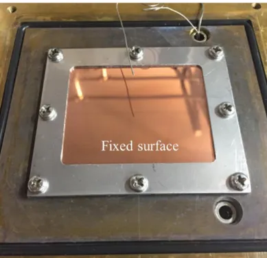
A high temperature resistant and thermal conductive paste (JunPus nano diamond thermal grease DX1) is used between the top of the heating block and the bottom of evaporator surface to reduce contact thermal resistance, as shown in Fig. 2.3. The thermal conductivity of this grease is 16 W/(mk). Then the evaporator surface can be fixed on the upper end of the heating block, which has been covered with a homogeneous thermal grease, as seen in Fig. 2.4. The power supply used in the experiment is pointed out from Fig. 2.5, which can be controled to provide the specified output-power.
Fig. 2.3 The press-fitted O-ring and thermal conductive grease.
Chapter 2 Experimental apparatus and measurement procedure
27
Fig. 2.4 The fixed surface on the upper end of the heating block.
Fig. 2.5 The experimental apparatus of two-phase loop thermosyphon.
Chapter 2 Experimental apparatus and measurement procedure
28
The photo of integrated setup is exhibited in Fig. 2.5. The insulation box is used to keep the thermosyphon apparatus operating at the constant environment. The air blower is set to maintain the temperature of the surrounding in the insulation box to simulate the environment temperature in the data center. Both of the heating block and the condenser chamber are totally covered with cellular insulant to reduce heat loss during the experiment and ensure the accuracy of the temperature measurements.
2.1.3 Mixed-wettability evaporator surfaces
This study focuses on the effect of mixed-wettability surfaces on loop thermosyphon boiling performance at sub-atmospheric pressures [65]. Schematic of the patterned surfaces used in the present study are shown in Fig. 2.6. The heating center area is 3038 mm
2and the thickness of the surface is 1.5 mm. They are made from polished copper (CA ≈ 80) and sometimes coated with the material with hydrophilicity, whose CA 10 [99]. After that, the hydrophilic surface is coated with hydrophobic spots (CA ≈ 150, material with hydrophobicity) [100]. The spots diameter ranges from 0.5 mm to 4 mm and these spots are distributed in a rectangular array with a pitch ranging from 1.5 mm to 6 mm.
Fig. 2.6 Schematic of a mixed-wettability evaporator surface.
Chapter 2 Experimental apparatus and measurement procedure
29
2.2 Experimental procedure 2.2.1 Leakage check
Leakage check is carried out to ensure that the setup maintains a consistent performance over a long period of time. Initially at 10 kPa, the pressure of the closed system is found to increase by only 0.2 kPa after a 24-hour period, which is considered an acceptable amount of leakage. After charging and degassing, the system valve is closed and air initially dissolved in the test liquid can be removed by vacuum degassing for 2 hours prior to the measurement. Each experiment lasts 4 5 hours.
2.2.2 Operating principle
The operating principle is as follows the working fluid is heated by the heater below the surface, and starts to boil on the evaporator surface. Then the vapor of the working fluid moves along the horizontal pipe driven by the pressure difference between the hot region and the cold region of the thermosyphon. In the condenser chamber, the vapor flowing from the evaporation section is condensed into the liquid, and the heat is dissipated into the circulating cooling water in the annular tube. Finally, the liquid from the condenser returns to the evaporator by gravity forming a circulation system. The thermosyphon works by repeating this cycle. The whole experimental system is developed to monitor and control the various process parameters through a data acquisition system.
2.3 Experimental measurement
The heat input Q
inis measured by thermocouples in the heat transfer block over 50
consecutive data (sampling rate at 3 points per second). During the experiments, all the
sides of heating block assembly are insulated to assure one-dimensional heat flow to the
boiling evaporator surface. All measurements have been conducted in a steady state,
which is judged by monitoring the outputs of the thermocouples. Various values of the
heat load ranging from 10 to 260 W are tested.
Chapter 2 Experimental apparatus and measurement procedure
30
Fig. 2.7 Schematic view of experimental system and thermocouple positions.
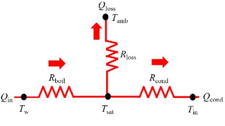
Fig. 2.8 Heat transfer model of the whole process during the experiment.
Chapter 2 Experimental apparatus and measurement procedure
31
2.4 Data calculation analysis
Fig. 2.7 and Fig. 2.8 describe the temperature measurement of the whole system and heat transfer model. The heat flux is evaluated as the ratio of the thermocouple temperature difference in the heating block to the distance between the two points:
3 1
3 1
x x
T q T
(2.1)
Here T
1and T
3are the temperatures of two thermocouples inserted in the heating block, x
1and x
3are the distances to the upper end of the heating block. is the thermal conductivity of the copper. The heat input Q
inis the heat flux q multiplied by the effective area of the heating surface:
qA
Q
in (2.2)
The thermal resistance is evaluated as the ratio of temperature difference to the heat input Q
in. The boiling thermal resistance is defined as the difference between T
wand T
satdivided by the heat input Q
in[7]:
in sat w
boil
Q
T
R T (2.3)
Here T
wis the wall temperature at the center of the evaporator surface measured by the thermocouple inserted in the hole inside, T
satis the saturation temperature measured using the thermocouple immersed in the liquid. The condensation thermal resistance is defined as the difference between T
vand T
individed by the condensation heat transfer rate Q
cond:
cond in v
cond
Q
T R T
(2.4)
Chapter 2 Experimental apparatus and measurement procedure
32
The condensation heat transfer rate Q
condis calculated by the temperature increase of the cooling water in the tube as follows
out in
p
cond
mc T T
Q (2.5)
Here m is the mass flow rate, c
pis liquid specific heat, T
outis the temperature of the cooling water at the outlet. Here T
inis the temperature of the cooling water in the condenser. The total thermal resistance is the sum of the boiling thermal resistance R
boiland the condensation thermal resistance R
cond. As described above, they can be expressed as:
cond boil
total
R R
R (2.6)
The flow rate of circulating water in the condenser part is set at 0.014 kg/s. The evaporation heat transfer coefficient, as one of the crucial performance parameters of the thermosyphon, is defined by the following equation [92]
) (
w satin
e
A T T
h Q
(2.7)
Here A is the evaporator surface area, Q
inis the heat input.
2.5 Uncertainty of the experimental data
The uncertainties of the experimental parameter measurements are analysed. The thermocouple uncertainty is 0.2 K. The uncertainty for the distance measurement of two thermocouples is 2%. The thermal conductivity uncertainty is considered negligible.
The uncertainty of the wall superheat is 4%. The uncertainty resulting from the
evaporator surface area is 0.1%. The uncertainty of the heat flux measurement can be
calculated by,
Chapter 2 Experimental apparatus and measurement procedure
33
2 22
x x T
T k
k q
q (2.8)
which gives 4.2%.
For HTC and the thermal resistance, the measurement uncertainties,
2 2
sat w
sat w
T T
T T q
q h
h
(2.9)
2 22
A A T
T q
q R
R (2.10)
are calculated to be 4.5% and 5.8%, respectively
.Chapter 3 Experimental study on HNTs coated surface
34
Chapter 3 Experimental study on HNTs coated surface
In this chapter, the analysis of the experimental results of HNTs coated evaporator surface is described. Different conditions, including heat input, filling ratios, and condenser temperatures are carried out to examine the influence factors of this thermosyphon.
3.1 Patterned surface
Firstly, the surfaces used in the experiments are made from polished copper (CA ≈ 80) and then coated with HNTs (Halloysite Nanotubes, Al
2Si
2O
5(OH)
4nH
2O) circular spots (CA ≈ 145) [113]. The spots diameter ranges from 1 mm to 4 mm and these spots are distributed in a rectangular array with a pitch ranging from 3 mm to 6 mm, as shown in Table 3.1.
Table 3.1 Hydrophobic spot parameters on evaporator surfaces of Type A, B, C, and D.
Case Spot diameter, d (mm) Pitch, p (mm)
Type A NA NA
Type B 1 3
Type C 2 3
Type D 4 6
Chapter 3 Experimental study on HNTs coated surface
35
Fig. 3.1 Copper mirror surface (Type A) and mixed-wettability surfaces (with hydrophobic spots coated on copper mirror surfaces), Type B, Type C, and Type D.
3.2 Comparison of experimental results 3.2.1 Experimental results
Table 3.2 Superheat of onset nucleate boiling on surfaces Type A, B, C, and D.
Case Superheat of ONB, T (K) q (kW/m
2)
Type A 20.2 128.5
Type B 3.2 30.2
Type C 3.1 29.3
Type D 2.1 21.5
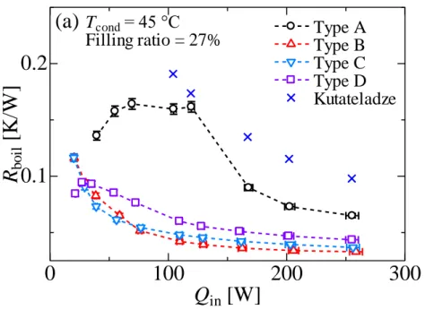
Fig. 3.2 Fig. 3.5 show the comparison of the experimental results of Type A, B,
C, and D surfaces, at heat inputs from Q
in= 10 W to Q
in= 260 W. Fig. 3.2 presents the
variation of the boiling thermal resistance as a function of heat flow rate. From the
results of an analysis, as shown in Fig. 3.2, it follows that the boiling thermal resistances
Chapter 3 Experimental study on HNTs coated surface
36
of Type B Type D surfaces are much lower than that of Type A. R
boildecreases accordingly with the increasing heating power due to the rising pressure in the system and more active nucleation sites. At higher pressure, decreasing surface tension, bubble departure diameter and increasing bubble frequency are achieved, which contribute to increasingly higher heat transfer coefficient [69]. The results of the Type A surface (copper mirror) is in agreement with those of Kutateladze correlation (Fig. 3.2), which is shown as follows:
7 . 7 0
. 0 35
. 4 0
10 0 .
7
v lva l arl l
a
Pl
L P ql
k
hl (3.1)
where l
ais Laplace coefficient, P
rlis Prandtl number, L
lvis the latent heat,
lis dynamic viscosity, 𝜌
lis the liquid density, is surface tension, k
lis the liquid thermal conductivity, h is the heat transfer coefficient, and P is the system pressure. In consideration of both the boiling and condensation thermal resistances, the total thermal resistances are shown in Fig. 3.3, which confirms that the thermal performance of this thermosyphon can be enhanced evidently by using the patterned surfaces.
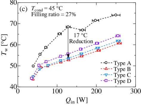
Fig. 3.4 represents the variation of the surface temperature as a function of heat flow rate. The temperatures of Type B Type D (hydrophobic spot coated surfaces) rise approximately linearly with the increasing heat input, which are much lower than that of Type A, resulting in a maximum reduction of 17 K, due to the excellent nucleate boiling performance. Fig. 3.5 represents the variation of the heat transfer coefficient as a function of the heat flux. The boiling heat transfer coefficient is dependent on the number of nucleation sites and size. Type B surface coated with 1 mm diameter spots reduces the departure diameter of the bubbles and increases the frequency of bubble departure, achieving the lowest thermal resistance. This can be explained as follows
when the large bubbles leave the wall, they are replaced by plenty of cold liquid that
requires longer waiting time to be superheated, therefore, resulting in larger bubble, and
longer waiting time [114].
Chapter 3 Experimental study on HNTs coated surface
37
Fig. 3.2 Comparison of experimental results of Type A Type D. (a) The boiling thermal resistance R
boilvs. the heat input Q
in.
Fig. 3.3 Comparison of experimental results of Type A Type D. (b) the total thermal resistance R
totalvs. the heat input Q
in.
0 100 200 300
0.1 0.2
T
cond= 45 °C Filling ratio = 27%
(a)
R
boil[K /W ]
Q
in[W]
Type A Type B Type C Type D Kutateladze
0 100 200 300
0.1 0.2 0.3
Q
in[W]
R
total[K /W ]
Type A Type B Type C Type D
(b) T
cond= 45 °C
Filling ratio = 27%
Chapter 3 Experimental study on HNTs coated surface
38
Fig. 3.4 Comparison of experimental results of Type A Type D. (c) the evaporator surface temperature T
wvs. the heat input Q
in.
Fig. 3.5 Comparison of experimental results of Type A Type D. (d) the heat transfer coefficient of the evaporator h vs. the heat flux at the evaporator surface q.
0 100 200 300
40 50 60 70 80
Q
in[W]
T
w[ °C ]
Type A Type B Type C Type D
(c) T
cond= 45 °C Filling ratio = 27%
17 °C Reduction
0 100 200 300
0 10 20 30 40 50
q [kW/m
2] h [ kW /m
2K]
Type A Type B Type C Type D Kutateladze
(d) T
cond= 45 °C
Filling ratio = 27%
Chapter 3 Experimental study on HNTs coated surface
39
![Fig. 1.1 Word cloud of the titles of articles about heat pipes [13].](https://thumb-ap.123doks.com/thumbv2/123deta/9917847.1919375/11.892.165.731.405.782/fig-word-cloud-titles-articles-heat-pipes.webp)
![Fig. 1.2 Distribution of the papers of the international journals on heat pipes in recent years [13]](https://thumb-ap.123doks.com/thumbv2/123deta/9917847.1919375/12.892.131.757.273.582/fig-distribution-papers-international-journals-pipes-recent-years.webp)