九州大学学術情報リポジトリ
Kyushu University Institutional Repository
有機蓄光の励起状態挙動に関する研究
林, 澤森
https://doi.org/10.15017/4060117
出版情報:Kyushu University, 2019, 博士(工学), 課程博士 バージョン:
権利関係:
2020
Doctoral Thesis
Studies on Excited-States Dynamics for Organic Long- Persistent Luminescence Materials
Zesen Lin
Department of Chemistry and Biochemistry Graduate School of Engineering
Kyushu University
i
Table of Contents
Chapter 1: Introduction ... 1
1.1. Terminology ... 2
1.2. Long Persistent Luminescence (LPL) in Inorganic Materials ... 4
1.2.1. Brief History ...4
1.2.2. Material Composition and Classification ... 7
1.2.3. Mechanism ... 9
1.2.4. Features ... 11
1.2.5. Kinetic Models ... 13
1.3. Photophysics of Organic Molecules ... 15
1.3.1. Excited State, Fluorescence, Phosphorescence and Delayed Fluorescence ...15
1.3.2. Exciplex and Charge Transfer ...18
1.4. Organic Long Persistent Luminescence (OLPL) ... 19
1.4.1. OLPL at Low Temperature ...21
1.4.2. Kinetic Models ...24
1.4.3. OLPL at Room Temperature ... 26
1.4.4. Mechanism of Room-Temperature OLPL ... 28
1.4.5. Advantages of Room-Temperature OLPL Materials ... 29
1.4.6. Open Issues of OLPL ... 31
1.5. Motivation and Outline of This Thesis ... 32
1.6. References ... 33
Chapter 2: Orange Organic Long Persistent Luminescence from an Electron Donor/Acceptor Binary System ... 37
2.1. Introduction ... 38
2.2. Results and Discussion ... 40
2.3. Summary ... 44
ii
2.4. Experimental ... 45
2.5. References ... 47
Chapter 3: Influence of energy gap between charge-transfer and locally excited states on organic long persistence luminescence ... 48
3.1. Introduction ... 49
3.2. Results and Discussion ... 52
3.3. Summary ... 73
3.4. Experimental ... 74
3.4.1. Materials and Synthesis ... 74
3.4.2. General Methods ... 76
3.4.3. Quantum Chemistry Calculations of the Dipole Moment ... 78
3.4.4. Film Fabrication ... 78
3.5. References ... 79
Chapter 4: Polymer-based Organic Long Persistent Luminescence Materials .. 80
4.1. Introduction ... 81
4.2. Results and Discussion ... 83
4.3. Summary ... 92
4.4. Experimental ... 93
4.4.1. Materials and Synthesis ... 93
4.4.2. General Methods ... 93
4.4.3. Film Fabrication ... 95
4.5. References ... 97
Chapter 5: Conclusions and Perspective ... 99
5.1. Conclusions ... 100
5.2. Perspective ... 102
5.3. References ... 103
iii
Acknowledgements ... 104
Appendixes... 108
List of Abbreviations ... 108
List of Publications and Conferences ... 112
1
Chapter 1
Introduction
2 1.1 Terminology
Long-persistent luminescence (LPL), also known as the glow-in-the-dark effect, noctilucent or long afterglow, is a self-sustained light emission phenomenon by which a material emits light for a very long time (longer than several minutes) after removal the excitation sources which are typically visible light, ultraviolet (UV) light, electron beams or high energy radiation such as X-, α-, β- or γ-rays.1, 2 Since the mid-1990s,3 highly efficient LPL materials were used in many commercial products for emission indicators without electricity, including luminous paints, watch dials, fire safety signs, and glow-in-the-dark toys (Figure 1- 1). Recently, LPL materials are also being investigated for applications in in vivo bioimaging because their long-lived emission can be used to take long time-resolved images after excitation.4
Figure 1-1. Applications of long persistent luminescence materials. (a) Glow-in-the-dark products. (b) in vivo bioimaging. ZGO is the abbreviation of ZnGa2O4:Cr3+. Adapted from Ref. 4.
3
All of the LPL materials that can be used at room temperature are made by inorganic materials until the organic LPL emitter was discovered in 2017.5 Therefore, the origin and meaning of the terminology related to the long-persistent luminescence phenomena and materials must first be explained, because of the different habits in inorganic and organic research fields.6
The word “phosphor” was invented for the denotation of “Bolognian stone” with the LPL phenomenon (see 1.2.1 for details) in the early 17th century and means “light bearer”. This meaning remains unchanged, and now this word is still used for calling the inorganic materials with persisting light emission of a few hours after the exciting radiation has ceased. The word
“phosphorescence” was derived from the word “phosphor” for representing this phenomenon.
To distinguish phosphorescence, the term “fluorescence” was introduced to denote the imperceptible short afterglow of the mineral fluorite (CaF2) after excitation. The word
“luminescence”, derived from the Latin word lumen with the meaning of light, is defined as a phenomenon in which a substance excited by external energy gives off the excitation energy as light. Obviously, luminescence includes both fluorescence and phosphorescence.
In modern usage, for inorganic materials, the luminescence from a substance during excitation is called fluorescence, whereas the afterglow that is detectable by the human eyes after stopping excitation is termed phosphorescence. However, for organic materials, the luminescence from a singlet excited state is called fluorescence, while that from a triplet excited state is referred to as phosphorescence (β-phosphorescence, to distinguish it from LPL which was also called α-phosphorescence7). The definition of the term “phosphor” is still dependent on users, because of the unclear definition. In a broad sense, the word is equivalent
4
to “a solid luminescent material”. In a narrow sense, the word “phosphor” is defined to mean
“inorganic phosphors” usually in a powder form and synthesized for practical applications, and rarely used to call single crystals, thin films, and organic molecules that exhibit luminescence.
Because of the vague definition of phosphorescence in the earlier time, LPL was always called long-period phosphorescence or long phosphorescence in the inorganic materials research field in the past. The word “phosphorescence” in organic materials research field is now mainly labeled as the long-lived luminescence from the triplet excited states, lasting not longer than a few minutes. In these materials, the luminescence decay curves with time follow the first-order reaction kinetics, which is significantly different from LPL. In recent years, luminescence phenomena similar to organic phosphorescence are also found in inorganic materials8, and researches in the inorganic LPL field have progressively started to use
“persistent luminescence” to replace phosphorescence to denote the LPL phenomenon.9 In this thesis, for distinguishing LPL and phosphorescence in the organic research field, the word
“phosphorescence” is not used to describe LPL phenomena.
1.2 Long Persistent Luminescence (LPL) in Inorganic Materials 1.2.1 Brief History
In many countries, there are many ancient stories about LPL phenomena, for example,
“night shining jewel” or “yeh kuang pi” in Chinese history.10 The earliest documented evidence of this phenomenon is about an afterglow ink and can be traced back to a thousand years ago, described in a compilation of historical and folk tales, “Xiāng Shān Yě Lù”, published in the Song dynasty (960-1279 A.D.) by Wen Ying (Figure 1-2a). The raw materials might be sulfide
5
phosphors (CaS) made from seashells and volcanic activity naturally.11 Possibly, the ink used was the first man-made LPL material. However, because of the dubious accuracy of this compilation, the recognized preliminary scientific reports were “De Illuminabili Lapide Bononiensi Epistola” by Montalbani and “Litheosphorus Sive De Lapide Boboniensi” by Licetus from the University of Bologna, Italy in 1634 and 1640, respectively.11, 12 These books discussed the properties of the Bolognian Stone (BaS) discovered by Casciarolo in 1602, which has an orange or reddish afterglow in the dark (Figure 1-2b). Limited to the scientific level at that time, the LPL mechanism of this stone was explained by Hölsä and Bettinelli et al. in 2012.
The LPL is originated from the emission of monovalent copper (Cu+) impurities peaking at ~ 610 nm in the reduced product (BaS) of the natural baryte (BaSO4).13 Because the knowledge and technology level required to explain the LPL mechanism is far beyond people’s at that time, only scattered researches were reported since the 17th century.1
In 1866, Sidot obtained good LPL emission from a ZnS crystal fabricated by a sublimation method, named Sidot’s blende.14 After approximate half century, P. Lenard and co-workers clarified the composition of the Sidot’s blende and explained that LPL is derived from the trace amounts of Cu+ in ZnS for the first time in history.1 Based on this result, they also found other alkali-earth sulfides exist LPL in the dark such as Bi3+, Eu2+ or Ce3+ doped (Ca1-xSrx)S, which are known as Lenard’s phosphors later.6, 11 Klasens used the elements of the iron group as co- doping electron traps and found ZnS:Cu+,Co+ exhibited a longer LPL duration.15, 16 However, although many physical models were founded to explain the detailed mechanism, all of LPL materials were sulfide-type until the end of the 20th century. Due to their weak brightness and short LPL duration as well as high hydrolyzability under ambient conditions, their applications
6
were limited. In order to prolong duration, some radioactive elements were introduced into sulfides.6 But since people have realized the severe health problems and environmental pollution caused by radioactive elements, such self-sustained light materials are difficult to enter the market.1
Figure 1-2. (a) Copy of the Chinese text describing the acquisition of a luminescent painting by Xu Zhi-e written for a compilation of historical and folk tales published in the Song dynasty (960–1279 A.D.) by Wen Ying, the English translation of the whole content can be found in page 446 of Ref. 11; (b) the Bologna Stone (BaS: Cu+) and its LPL.
The true widespread use of LPL materials began with the modern LPL materials, SrAl2O4:Eu2+,Dy3+, developed by Murayama and his colleagues in the mid-1990s.3 Comparing with traditional sulfide-type LPL materials, SrAl2O4:Eu2+,Dy3+ is capable of over 30 h of LPL before the emission intensity dropping upon 0.32 mcd/m2 (Figure 1-3a), which is the lower limit of dark-adapted sensitivity of human eyes.3 The emission color of this material is green peaking at 520 nm that matches the human's photopic vision (maximum sensitivity at 555 nm) and scotopic vision (maximum sensitivity at 510 nm).17, 18 The broad absorption band (the edge
7
over 450 nm, Figure 1-3b) is suitable for the excitation by conventional fluorescent lamps (also white light-emitting diodes). With these nearly perfect properties, SrAl2O4:Eu2+,Dy3+ with the famous brand name, LumiNova®, rapidly prevailed in the market. In 2001, Lin et al. reported the first silicates type LPL material, Sr2MgSi2O7:Eu2+,Dy3+, with the blue emission peaking at 476 nm and longer duration than that of SrAl2O4:Eu2+,Dy3+.19 Today, these two materials are the most common LPL material in the market, which is why the LPL is always green or blue emission in our perception.
However, although many new LPL materials have invented for more than two decades after the discovery of SrAl2O4:Eu2+,Dy3+, surprisingly, the number of known materials with a decent LPL brightness and duration is still rather limited (see 1.2.2, Table 1.1).
Figure 1-3. (a) The long-persistent luminescence characteristics of several inorganic LPL materials; (b) Emission and excitation spectra of the SrAl2O4:Eu2+,Dy3+; (c) Proposed emission mechanism of SrAl2O4:Eu2+,Dy3+.Adapted from Ref. 3.
1.2.2 Material Composition and Classification
In general, the existing inorganic LPL materials are made by a host material with two kinds of dopants: activators and traps.1, 2 Although a wide variety of inorganic host materials are used as luminescent compounds, relatively few hosts are used to persistent luminescence, such as aluminates, silicates, sulfides and phosphates, etc.2, 20-22 Among them, aluminates and
8
silicates are currently the most mainstream host materials. Activators, namely emission centers, include lanthanide ions (e.g., Ce3+, Eu2+, Nd3+, Er3+, in which Eu2+ is the most popularly used), transition metal ions (e.g., Cr3+, Mn2+, Mn4+, Ni2+) and main group metal ions (e.g., Pb2+, Bi3+), etc.20, 23-25 Traps contain crystallographic defects (e.g., oxygen vacancies, Farbe center, anti- site defects) and metal ion co-dopants as impurities (e.g., Cu+, Co2+, Ti3+) or induced intentionally (e.g., Dy3+ in SrAl2O4:Eu2+; Nd3+ in CaAl2O4:Eu2+; Cr3+ in Y3Al2Ga3O12:Ce3+), etc.1, 3, 26-31 The emitting centers can also play the role of trap centers, e.g., Cr3+.32, 33 The best LPL materials currently contain intentionally introduced aliovalent or isovalent co-dopants as traps. Generally, the concentration of dopants as activators and co-dopants as traps in inorganic LPL materials is lower than 2% and mainly 1%, which is obviously lower than corresponding inorganic fluorescence materials.20
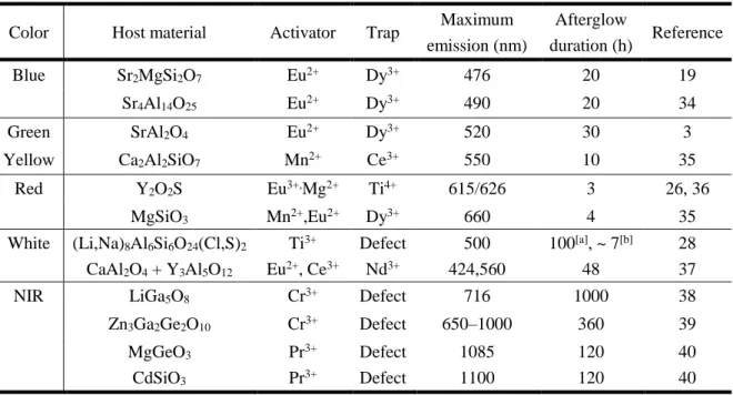
Table 1-1. The reported best different color-emitting inorganic LPL material
Color Host material Activator Trap Maximum emission (nm)
Afterglow
duration (h) Reference
Blue Sr2MgSi2O7 Eu2+ Dy3+ 476 20 19
Sr4Al14O25 Eu2+ Dy3+ 490 20 34
Green SrAl2O4 Eu2+ Dy3+ 520 30 3
Yellow Ca2Al2SiO7 Mn2+ Ce3+ 550 10 35
Red Y2O2S Eu3+,Mg2+ Ti4+ 615/626 3 26, 36
MgSiO3 Mn2+,Eu2+ Dy3+ 660 4 35
White (Li,Na)8Al6Si6O24(Cl,S)2 Ti3+ Defect 500 100[a], ~ 7[b] 28 CaAl2O4 + Y3Al5O12 Eu2+, Ce3+ Nd3+ 424,560 48 37
NIR LiGa5O8 Cr3+ Defect 716 1000 38
Zn3Ga2Ge2O10 Cr3+ Defect 650–1000 360 39
MgGeO3 Pr3+ Defect 1085 120 40
CdSiO3 Pr3+ Defect 1100 120 40
[a] Duration by detector. [b] Duration upon 0.32 mcd/m2.
9
According to the emission color, the inorganic LPL materials are generally divided into five groups: blue, green, red, white, and near-infrared (NIR).2 Here, only the best inorganic long afterglow material types of different colors were summarized (Table 1-1). Some related reviews and books have been published to summarize the existing inorganic LPL materials in detail.1, 2,
20, 23 The host materials mainly contains six families: aluminates, silicates, aluminosilicates, oxides, oxysulfides, and sulfides.41 The durations of LPL materials with yellow and red emission are limited comparing to other color LPL materials.
1.2.3 Mechanism
For understanding the mechanism of the LPL in inorganic materials, many physical models have been proposed,1, 3, 20, 42 ranging from very basic conceptual models to complex systems with multiple charge traps of various types and depths. But all of these models are based on the trapping–detrapping mechanism framework: 1) Excitation process: the excitons are generated by external excitation; 2) Trapping process: the generated electrons or holes (charge carriers) are separated and captured by the electron or hole traps instead of the direct radiation. Because of the long lifetime of trapped charge carriers, this material can store the excitation energy for a long time. Therefore, this phenomenon can also be called an “optical battery”; 3) Detrapping process: after cutoff of the excitation, the captured charge carriers are only gradually released from these traps mainly by thermal activation or back tunneling assisted by thermal fluctuations;
4) Recombination luminescence process: the detrapped charge carriers recombined with their counter charge carriers and regenerated excitons that emit the luminescence.
The difference between these models lies in the details of the framework, such as whether the host is excited or the activators are excited, whether the electrons or holes are trapped, and
10
whether the trapping and detrapping processes of charge carriers between traps and activators are through the conduction band (CB) or the valence band (VB) of the host materials or direct tunneling, as well as details of redox species in these inorganic LPL materials. Both energy levels of activators and traps are located inside the forbidden band of host materials. Normally, the trap energy levels are less than 1 eV below the bottom of the CB (electron trap) or above the top of the VB (hole trap).
However, these models are more or less inadequate to explain some experimental phenomena, and there is no universal model until now. Researchers of inorganic LPL materials always chose the relatively appropriate model to explain the phenomena of their materials. For example, in the Matsuzawa model (Figure 1-3c),3 Eu2+ ions are as the activators (Eu2+/Eu+) and holes are assumed to be the main charge carriers and captured by the traps, Dy3+ (Dy3+/Dy4+).
This model can explain the influence of the rare earth codoping effect well. However, this model ignored the observed weak LPL in non-codoped SrAl2O4:Eu2+.43 Moreover, Eu+ and Dy4+ ions are chemically unstable ions.42
Based on the previous studies, the long-lived separated charges from photo-generated excitons are critical to LPL, which are stabilized by traps with suitable depth in inorganic LPL materials. The recombination of these trap-stabilized long-lived separated charges resulted in the key feature, i.e., the LPL obeying a power law (see 1.2.4) in the long time scale as shown in Figure 1-3a and 1-4. If the energy level of traps is too shallow, the captured electrons can easily escape from traps at room temperature, resulting in too short LPL duration or even no observable LPL. On the other hand, too deep trap energy level will lead to a few or no escaped electrons at room temperature, which is also not appropriate to the LPL performance.
11 1.2.4 Features
Two apparent features are always used to distinguish LPL and phosphorescence: (i) the almost identical spectra between photoluminescence and LPL (Figure 1-4c&d); (ii) long emission duration from minutes to even days after cutoff excitation sources. The first feature can be found in most inorganic LPL materials with two dopants because the fluorescence and LPL come from the identical energy state of emission center ions.1 This is an evident discrepancy between LPL and phosphorescence since the phosphorescence always shows a conspicuous redshift comparing with the corresponding fluorescence (the reason see 1.3.1).
Figure 1-4. The LPL performance of a commercial inorganic LPL tape (Super alpha-FLASH, 1 cm2 area):
semi-logarithmic plots (a) and logarithmic plots (b) of the emission decay profiles with different excitation duration; Emission spectra during photoexcitation (c) and after the excitation (d) of inorganic LPL material.
All samples were 1 cm2 and were excited for 60 s by a 340-nm LED source with the same power of 230 μW at 300 K.
12
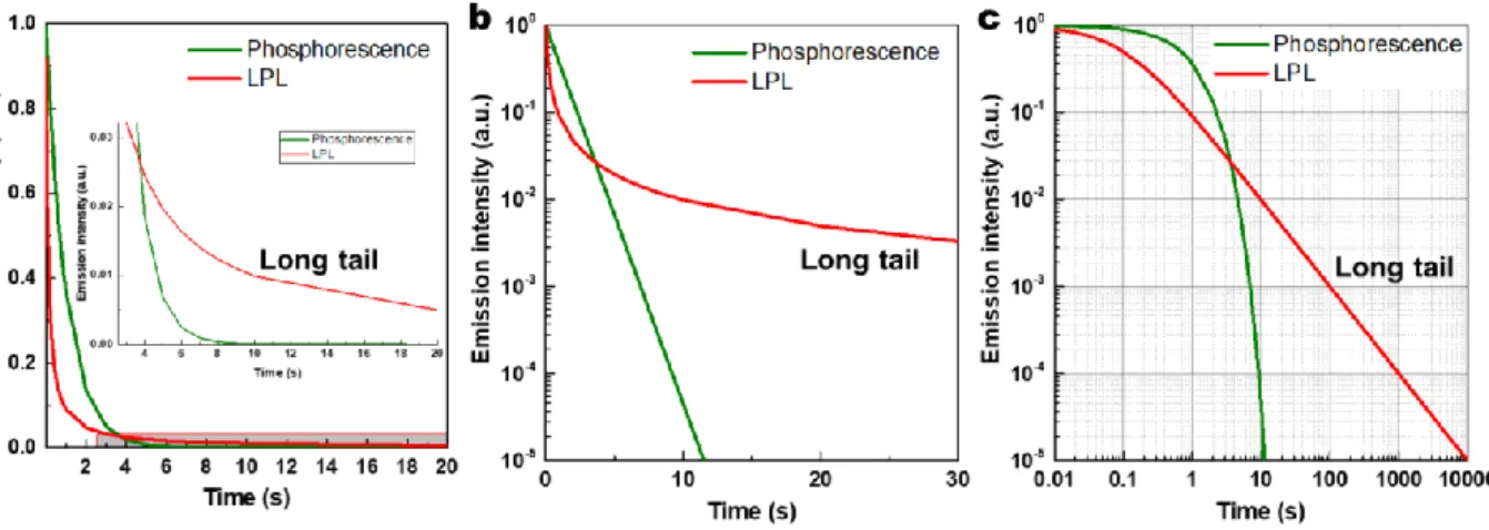
The second feature is crucial and entirely different with room-temperature phosphorescence (generally up to seconds) because their decay follows the different law: the LPL (refer in particular to the isothermal luminescence) obeys a power law (I(t) ~ t−m, with m
= 0.5~2, mostly 1, hyperbola44, 45) in the long time scale as shown in Figures 1-3a and 1-4a&b (the straight-line on the log–log plot is often called the signature of a power law.46), while the phosphorescence follows an exponential law (the straight line on the semi-log plot,47 specifically log-linear plot in this case as shown in Figure 1-5).
The long emission decay properties of LPL originate from the mathematic properties of the power law. The one important mathematic property of the power law is that the power-law graph has a longer tail than that of the exponential law (Figure 1-5).46, 48 This is the reason why the duration of LPL is appreciably longer than that of phosphorescence. The scale invariance (scale free) of power law leads to the straight-line on the log-log plot.48 However, the phosphorescence decay obeying the exponential law is slow in a short time-scale but fast in a long time-scale (Figure 1-5).
Figure 1-5. The ideal emission decay profiles of phosphorescence and LPL on (a) linear, (b) log-linear, (c) log–log plots. Phosphorescence follows an exponential decay I(t) = exp (-t), and LPL a power-law decay I(t)
= (1+10t)-1.
13
Another mathematics property of the power law is the lack of well-defined average value (mean): a power-law x-k has a well-defined mean over x [1, ∞) only if k > 2.48 Therefore, we cannot obtain the lifetime of LPL (I(t) ~ t−m, with m = 0.5~2). On the other hand, the mean of experiential law 𝑒−λ𝑥 is 1/λ, in which λ is a constant. So the lifetime of phosphorescence is a constant. The excitation conditions containing the excitation duration must be identical to evaluate commercial LPL materials,1, 49, 50 while the identical excitation power and duration are not required to evaluate phosphorescence.
In addition to these two apparent features between LPL and phosphorescence, LPL materials often show thermoluminescence (TL) or thermally stimulated luminescence (TSL), although that is not found in phosphorescent materials.51 The phenomenological definition of TL is as follows “The type of light emission that occurs when the heat is applied to an insulator or to a semiconductor which has been previously irradiated by ionizing radiations”.52 The LPL can exhibit TL even excited by non-ionizing radiations, e.g., ultraviolet- visible (UV-vis) light. Since the TL profile provides information on “trap depth” that is the energy required for carriers to escape from the traps, the TL profile is used to analyze the emission mechanism. However, phosphorescent materials do not exhibit TL and often quenched by non-radiative transitions with increasing temperature.
1.2.5 Kinetic Models
Based on empirical kinetics, when a luminescence process controlled by a rate-determining step with the reaction order n > 1, the relationship between luminescence intensity I (t) and time t obeys a power law
14
0
1 1
1 1 1 1
0
(0) (0)
( )
[1 ( 1) ] [1 ( 1) (0) ] 1
n L
n n n n
n n n n n n
L L
k a I I
I t t
n k a t n k I t
( )
(1-1)
in which kL is the rate constant of the whole luminescence process, a0 is the initial concentration of reactants of the rate-determining step. Here, the concentrations of all reactants are equal to at at the arbitrary time t and τ is the lifetime. τ = (n-1)-1kL-1a01-n means that the lifetime is depends on a0. However, t-1 power law cannot be obtained from empirical kinetics.
According to the trapping-detrapping mechanism (the detrapping process is the rate- determining step, see 1.2.3), if the retrapping possibility of electrons or holes is assumed to be negligible, the afterglow decay profile will obey first order kinetics, which is described by Randall and Wilkins in 1940s.53 If the retrapping probability is equal to the electron-hole recombination probability, the afterglow decay profile can be described by (1 + t)−2 behavior when the limit t → ∞, i.e., second order kinetics, as derived by Garlick and Gibson in 1948.54 May and Partridge described general order kinetics.55 Therefore, the above assumptions are ideal and do not correspond to the actual situation.
In order to explain the t-1 power law, many kinetic models based upon different assumptions have been proposed in history.51, 52, 56 They can be divided into two categories based on different assumptions: trap depth distribution model and electron tunneling model.
Several reviews51, 52, 56 have clearly summarized the merits and demerits of these models.
The combination of multi-exponential processes can mimic a power law.57 Thus, a common approach is to assume the presence of multiple discrete energy levels obeying first order kinetics. Many researchers fitted the delay profile by a multi-exponential (three or more) function and called these exponential components “fast,” “slow,” or “intermediate”.56 However,
15
these exponential components are always difficult to interpret physically. Moreover, the large number of parameters involved make the fitting procedure unreliable.56
1.3 Photophysics of Organic Molecules58-60
1.3.1 Excited State, Fluorescence, Phosphorescence and Delayed Fluorescence
For the photophysics of organic molecules, the scope of discussion is mainly the electronic state change of molecules, of which energy range is in the UV-vis band. Therefore, in terms of organic molecular photophysics, the electronic state of the molecule is also denoted by the molecular state. The ground state of a molecule is its lowest-energy state, that is, electrons preferentially occupy all molecular orbitals from the lower energy levels. When the molecule absorbs electromagnetic waves in the UV-vis band, an electron in the ground state molecule will transit to the higher energy orbitals. At this time, this molecule is on an excited state.
Although there are a huge number of possible excited states for a molecule, in theory, only two or three excited states normally need to be considered for photophysical and photochemical discussions of organic molecules, because of the energy range of UV-vis light.
The ground state of conventional organic molecules is closed-shell (all electrons paired and two electrons per orbital). In a closed-shell molecule, the occupied orbital with the highest energy level is called the Highest Occupied Molecular Orbital (HOMO), and the unoccupied orbital with the lowest energy level is called the Lowest Unoccupied Molecular Orbital (LUMO). For many organic molecules, the orbital that is losing an electron mainly is the HOMO, while the orbital receiving the electron is the LUMO or an orbital near it in energy (e.g., LUMO+1).
16
One molecular orbital can be occupied by a pair of electrons with two spin states: spin-up and spin-down (the spin quantum number s is -1/2 and 1/2, respectively). When the total electron spin quantum number (S) of this molecule is zero, there is only one spectral line from this molecule state, which is a single state (N = 2S+1, N is the number of spectral lines. In this case, N = 1). When S = 1/2, N = 2, the molecule is at a doublet state. When S = 1, N = 3, the molecule is at the triplet state. Because the ground state of the organic molecule is a closed shell, its ground state is a singlet state (S0), and the excited state is a singlet state (Sn) or a triplet state (Tn). In the same electronic configuration, the triplet excited state is more stable than the singlet excited state because of the exchange interaction of two unpaired electrons located in two different orbitals. Thus, the molecular excited state can automatically convert from Sn to Tn through the intersystem crossing (ISC) process.
Since the molecules in their excited states are unstable, they tend to release energy through radiative transitions and non-radiative transitions. The radiative transition of an electron from a high energy level orbital to a low energy level orbital is the luminescence process. According to the Kasha rule, the luminescence process of most organic molecules involves only the lowest excited states (S1 or T1), because relaxations (internal conversion) from the higher excited states (Sn or Tn) to the lowest excited states (S1 or T1) are much faster than that of luminescence.
The radiative transition from S1 to S0 is called fluorescence. The fluorescence emission is spin- allowed radiative transitions with the large radiative rate constant (105~109 s-1, normally larger than 106 s-1), that is why it is named fluorescence (see 1.1). If the luminescence is from T1 to S0, it is called phosphorescence. Because the transition is spin-forbidden, the rate constant of phosphorescence is small (10-2~106 s-1, normally smaller than 104 s-1). Since the small exchange
17
interaction of two electrons on the HOMO and the LUMO, the T1 state is lower than the S1
state, leading to the red-shift of phosphorescence from fluorescence.
Figure 1-6. The simplified Perrin–Jablonski diagram without higher energy level excited states and rotation and vibration levels. Solid lines with an arrow indicate radiation transition, while dash lines with arrow donate non-radiative transition.
However, in some cases, the emission has the same spectral distribution with the normal fluorescence but a much longer lifetime (102~106 s-1). This so-called delayed fluorescence originates from an up-conversion process from T1 to S1 and can be separated into two types based on different up-conversion mechanisms: “P-type” delayed fluorescence and “E-type”
delayed fluorescence. The P-type delayed fluorescence derives from triplet–triplet annihilation (TTA), which can produce fluorescence emission from the reaction of two triplet states. The E- type delayed fluorescence is also called thermally activated delayed fluorescence (TADF) because the key up-conversion is a thermally activated process through reverse intersystem crossing (RISC). The efficient RISC can occur when the energy gap between S1 and T1 (ΔEST) is very small (< 0.2 eV), because of a small overlap between the wave functions of the HOMO
18
and LUMO levels.61-63 Fluorescence, phosphorescence, TADF and corresponding non-radiative transitions obey the first-order kinetic, because of only one reactant in the rate-determining step.
Therefore, the decay profiles of these processes usually follow the exponential law.
1.3.2 Exciplex and Charge Transfer
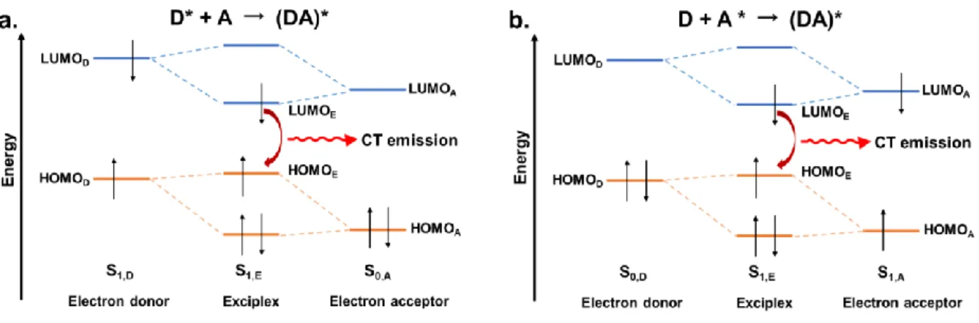
In the condensed state, an excited molecule can spontaneously be stabilized by some intermolecular interactions. The excited molecule can transfer a fraction of charge to another different molecule on the ground state and forms a stable complex, i.e., exciplex. In exciplex, the electron-donating (hole-accepting) molecule is called the electron donor, or simply donor (D), while the electron-accepting (hole-donating) molecule is called the electron acceptor, or simply acceptor (A). This stabilization for generating the exciplex can be explained as the partial mixing of frontier orbitals of donor and acceptor molecules (Figure 1-7). Because the interaction between the donor and acceptor is small, this interaction does not form chemical bonds. But this orbital mixing causes an electron/hole delocalization on these two molecules.
As a result, the donor transferred a portion of the negative charge to the acceptor during the process forming the exciplex. The process is called charge transfer, to distinguish the concept electron transfer which normally is denoted as the process that an electron is completely transferred to another molecule. As shown in Figure 1-7, the gap between HOMO and LUMO of exciplex is smaller than that of the corresponding donor and acceptor, so the exciplex always shows a redshift emission.
19
Figure 1-7. The donor-acceptor orbital mixing to generate an exciplex: (a) an excited donor and an acceptor on the ground state; (b) a donor on the ground state and an excited acceptor.
1.4 Organic Long Persistent Luminescence (OLPL)
Phosphorescence is known to have long emission duration as the organic molecule because of the slow spin-inversion process (see 1.3.1). Since the competition of non-radiative transition from T1 to S0 is greatly accelerated by increasing the temperature, a large phosphorescence rate constant is preferred to obtain the room-temperature phosphorescence (RTP). In contrast, a small phosphorescence rate constant is required to get a long phosphorescence lifetime.
Therefore, the long-lived RTP of organic molecules is limited in principle. Since the main cause of non-radiative decay owes to the molecular motion, long-lived RTP has been reported by suppressing molecular motion in the solid-state matrix in the middle of the 20 century.64-66 Now, many RTP from organic molecules have been adopted: molecular design based on n-π transition;
usage of rigid matrix66, 67, e.g., polymer68, micelles69, 70, cyclodextrins71, crown ethers72 and metal-organic framework (MOF)73; generation of new long-lived triplet states by co- crystallization74, H-aggregation75, 76, intermolecular ionic77, hydrogen or halogen bonding78-80, etc.64, 65 However, all of these efforts did not change the first order kinetic feature of phosphorescence, i.e., the exponential law. Owing to the mathematic “short tail” feature of the
20
exponential law, it is impossible to obtain LPL just through extending RTP.
To obtain LPL emission from organic materials, it is the key to obtain the power law emission decay. However, obeying the power law is a necessary condition but not a sufficient condition to judge whether a luminescence process is LPL or not.
For example, the P-type delayed fluorescence derived from TTA can obey a power law (t-2 law) in the short time scale:
2
TTA 0
DF 2
TTA 0
0.5 [T ] ( ) (1 [T ] ) I t fk
k t
,kTTA[T ]t kphosknr (1-2)
But it will obey an exponential law in the long time scale because the delayed fluorescence changes into the phosphorescence:
2
DF( ) 0.5 TTA[T ] exp[ (0 phos nr) ]
I t fk k k t , kTTA[T ]t kphosknr (1-3) in which f is the probability that the reaction complex has spin 0 from Smoluchowski’s theory;
kTTA, kphos, and knr are the rate constant of TTA, phosphorescence, and non-radiative transition of T1 state; [T0] and [Tt] are the concentration of T1 excitons at time 0 and t, respectively.59 This is because the TTA, phosphorescence, and non-radiative decay are all parallel reactions from T1 excited state. Moreover, if a reverse process of TTA (singlet fission) generates the geminate triplet excitons, the emission decay profile of the diffusion-mediated delayed fluorescence will be t-1.5 law (one and three dimensions) or t-1 law (two dimensions) in the short time scale (< 1 μs).81
This example revealed an important condition to obtain LPL. The metastable species generating LPL can hardly be quenched by other quick processes. Therefore, the metastable species must have a long lifetime for the LPL emission over seconds. One possible option is to use the separated geminate charges as the metastable species because the separated
21
geminate charges can only disappear by recombination but cannot disappear at the isolated states (Figure 1-8). Actually, inorganic LPL materials store the excitation energy into the separated charges by using trap sites. The separated charges should not convert to other stable ionic states by redox reaction or recombine without radiation.
Figure 1-8. The comparison between the afterglow emission process obeying the exponential law and obeying the power law. The uncommented dash arrow represents non-radiative transitions.
1.4.1 OLPL at Low Temperature
OLPL from the recombination of geminate ion pairs in condensed media at a fixed low temperature is known as isothermal luminescence (ITL).82-84
Lewis and co-workers investigated the photoionization (or photo-oxidation) of many easily oxidized organic molecules (amines, phenols, dyes, etc.) in frozen organic solution in the 1940s.85-87 They found some of these compounds can exhibit LPL (even till 1 hour) in the rigid solution after excited by a high-intensity mercury-light source.82 Linschitz and Berry extended these studies (Figure 1-9) and found that the compounds containing a lone pair (on the nitrogen
22
atom, oxygen atom, or carbanion), which can be easily oxidized and have a well-marked phosphorescence, show LPL.82 Thus, the amines give much brighter light emission than the corresponding ethers or phenols. They also described the importance of solvent since the amine solvent may afford better electron traps and thus enhance the luminescence. They also identified the presence of the solvated electrons generated by the photo-oxidization as follows. In addition, the neutral radical resulting from photo-oxidation of a negative ion exerts no long-range coulomb attraction on the electron, and thus even shallow solvent traps suffice to prevent immediate recombination.82 Lewis and Kasha had already suggested the separated geminate radical ions in this LPL process originate from a stepwise two-photon ionization.7
Figure 1-9. Structures of organic molecules as solute investigated by Linschitz and Berry as well as rough results of LPL performance. The solvent EPT is a mixture of ether, isopentane, triethylamine, 2:3:3 or 5:5:2.82
After their pioneering works, many examples of low-temperature OLPL were reported, while the high energy ionizing radiations like γ-ray and electron beam are used as the excitation source.83, 88-91 The adopted condensed media are always organic solvent glass at liquid nitrogen temperature in these reports.
23
In 1960, Nikolski and Buben firstly reported TL (see 1.2.4) of polymer solids like polyethylene, paraffin, polyisobutylene, Teflon, natural and synthetic rubber, which were irradiated by electron beam at 100 K.92, 93 The TL glow curve of the irradiated polymer was developed to obtain the information on the motional relaxation of polymer solids. However, there are still some unknown problems on the mechanism of luminescence owing to lack of information on the nature of electron traps.84
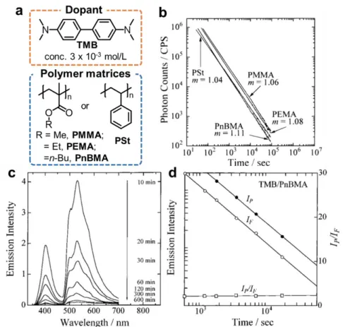
In the 1990s, Yamamoto et. al.84, 94 observed the low-temperature OLPL (t-m law, m ≈ 1, at 20 K, Figure 1-10) from a polymer solid doped with small organic molecules after excited by a laser. The dopant, N,N,N′,N′-tetramethylbenzidine (TMB), can easily form long-lived radical cations by photo-ionization as Lewis reported.85-87 The LPL performance was changed by the polarity and the glass-transition temperature (Tg) of polymers. The LPL spectrum contains both the fluorescence and phosphorescence of TMB at the low temperature (< 210 K) (Figure 1-10c). Moreover, both LPL decay profiles at fluorescence and phosphorescence regions show power-law decay (Figure 1-10d), which indicates both fluorescence and phosphorescence are controlled by the charge recombination process. The intensity ratio of phosphorescence (IF) to fluorescence (IP), IF/IP in the TL spectra indicates that the photo- generated electrons in the poly(alkyl methacrylate)s are more stable than that of in the polystyrene. However, the LPL was quenched at room temperature. A 351-nm pulse laser does not cause direct ionization of TMB, while it can cause two-photon ionization because of the high optical density of the laser.
24
Figure 1-10. (a) The structures of low-temperature OLPL materials; (b) LPL duration profile of TMB doped in polymer solids photoirradiated at 20 K. (c) Emission spectral change in the LPL for the TMB chromophore doped in a PnBMA film over the time range from 10 to 600 min after the photoirradiation at 20 K. (d) Dependence of the fluorescence intensity IF (open circles), the phosphorescence intensity IP (closed circles), and the intensity ratio IP/IF (open squares) on time change for the ITL at 20 K of the TMB doped in a PnBMA film. The values of m represent the slope of the LPL duration profile. Modified from Ref. 84, 94.
1.4.2 Kinetic Models
Similar to LPL in inorganic materials, the function of the low-temperature OLPL intensity and duration normally follows
( ) (0)
(1 )m I t I
t
, m ≈ 1 (1-4)
in which the parameters, I(0) and α, depend on irradiation time and dose rate.95, 96 As previously described in 1.2.5, it cannot be explained by an empirical kinetic. Historically, there were many proposed models to explain this power law. Normally, these models can be separated into two
25
types according to the recombination of geminate ions by diffusion or electron tunneling.
1. Diffusion model. The condensed state of organic molecules does not have VB and CB like inorganic materials while they have separated molecular frontier orbitals. In the diffusion model, we consider the distribution of electrons (radical anions) after the charge separation process. The model based on the diffusion-controlled recombination is the earliest and most popular model. Debye and Edwards proposed I (t) ∝ t−m, m = 1 in terms of a diffusion process and a spatial distribution function of trapped electrons. However, this model cannot explain m>1 because it neglects the normalization of the distribution function, which leads to an infinite of the total amount of ionic species when m = 1.97 By using a normalized distribution function, Abell and Mozumder gave a revised model showing that, when t→∞, m is 1.5, which can explain the change of m value over time.98 Hong and Noolandi also derived the recombination rate R (t) ∝ t-m, m = 1.5 by solving the time-dependent Smoluchowski equation with Coulomb potential.99 Stolzenburg, Ries and Bässlerproposed I (t) ∝ t-m, m = 1 based on the Hong-Noolandi model by considering the energetic relaxation of carriers subject to the random walk.100 Hamill and Funabashi explained the t-
m law by using a non-Gaussian diffusion model in which hopping time distribution is an asymptotic type derived from the continuous-time random walk mode by Scher and Montral.101
2. Electron tunneling model. In the 1970s, Kieffer, Meyer, and Rigautreported the LPL emission derived from the electron recombination without thermal activation because LPL decay kinetics do not change from 4 to 77 K.102, 103 Therefore, the electron tunneling model has been used to explain the LPL at low temperatures. The Tachiya-Mozumder model
26
shows I (t) ∝ t-m, m is very close to unity over a wide time range.104 Hama et al. found the distance distribution of cation-electron pairs could be obtained by Laplace inverse transformation of the ITL decay based on an electron tunneling model. The exponent m (equation 1-4) depends on irradiation time and dose rate.96 Ohkita et al. explained their results by this tunneling model.94
1.4.3 OLPL at Room Temperature
Although the OLPL is discovered at low temperature by using two-photon ionization of polymer systems, OLPL at room temperature is realized after almost 20 years. The problem was how to obtain stable separated geminate charges by a weak excitation light source at room temperature.
In 2017, Kabe and Adachi realized OLPL at room temperature by using a mixed film of
the electron donor TMB and an electron acceptor 2,8-
bis(diphenylphosphoryl)dibenzo[b,d]thiophene (PPT), which is a host material commonly used in OLEDs.5 They found when the TMB concentration is low (1 mol%), the film can show LPL lasting for more than one hour after excited by low-power excitation at room temperature (Figure 1-11). The emission originates from the exciplex formed between TMB and PPT, but not from the phosphorescence of TMB or PPT. Moreover, the afterglow obeys a power-law but not an exponential law. Because both two features are similar to inorganic LPL, this is the first room-temperature OLPL material in the world. Comparing with previous low-temperature OLPL materials, the breakthrough in this research is two points: 1. the use of exciplex (CT exciton) to ease the charge separation (CS) process at room temperature due to the small binding energy of CT excitons compared to the Frenkel excitons in a low-temperature OLPL system.
27
Thus, CS can happen even by a weak excitation light source. 2. PPT as the electron acceptor and transport material possesses a lower electronic affinity than that of solvent glasses or polymers in low-temperature OLPL systems. This stabilizes PPT radical anions at room temperature with the enough HOMO-LUMO energy gap with TMB for efficient emission.
They also demonstrated the independence of OLPL performance to the fabrication methods: spin coating, thermally evaporating, and melt casting.105 Moreover, a new OLPL system, m-MTDATA/PPT with 1.5-times improved LPL duration over the TMB/PPT system, was demonstrated due to the higher PLQY (32%, but 13% for TMB/PPT).
Figure 1-11. Binary room-temperature OLPL systems. (a) Material components and their chemical structures; (b) Logarithmic plot of the emission decay profile of a 1 mol% TMB/PPT and m-MTDATA/PPT melt-casting film (excited by 340 ± 5 nm LED, excitation power, 600μW; excitation time, 60 s; sample temperature, 300 K). The PL and OLPL spectra of m-MTDATA/PPT (c) and TMB/PPT (d). Adapted from Ref. 5, 105.
Multi-component OLPL systems were also reported to realize wide-range emission color tuning from greenish-blue to red and even warm white by Förster energy transfer (FRET)
28
strategy.106 The additional emitter dopants also improve emission brightness and extend duration through efficient radiative decay and the trapping of electrons. This result means suitable carrier traps is also important to enhance OLPL systems as that in inorganic LPL systems.
1.4.4 Mechanism of Room-Temperature OLPL
The emission mechanism of OLPL is proposed based on the presence of TMB radical cations after photo-excitation (Figure 1-12 a).5, 106 The exciplexes generated by a charge transfer between the photo-excited state of acceptor and donor dissociated to form partially charge- separated (CS) states, i.e., geminate radical ion pairs; Because the very low concentration of TMB in PPT, the separated electrons on PPT can hop among PPT molecules and difficultly recombine with the hole on TMB owing to the low probability; Finally, this slow charge recombination (CR) caused by continuous-time random walk of electrons in PPT leads to the LPL with a power-law emission decay at room temperature. Moreover, because of the small ΔEST of the exciplex, the generated triplet excitons on exciplex can convert to the singlet excitons of exciplex by the RISC process. Therefore, this system does not exhibit the phosphorescence of exciplex at room temperature.63, 107
For the ternary OLPL system (Figure 1-12 b), the extra emitter dopants play the role of traps and extend the lifetime of the charge-separated state. On the other hand, the emitter dopants will seize the excitation energy of exciplex by FRET after CR and emit self- fluorescence. Based on the TADF-assisted fluorescence mechanism108, almost 100% excitons can be transferred to the emitter dopants and the highly efficient emission can be realized because the PLQY of the fluorescence emitter is higher than the exciplex.
29
Figure 1-12. Mechanisms of room-temperature OLPL (a) in the binary system; (b) in the ternary system with emitter dopant; (c) Emission mechanisms. Adapted from Ref. 106.
1.4.5 Advantages of Room-Temperature OLPL Materials
Room-temperature OLPL materials have several advantages compared with inorganic LPL materials.
1. Free of rare earth elements. The commercial highly efficient inorganic LPL materials contain rare earth elements as activators or traps. Although the doping concentration is low, the mining and refining of rare earth elements always cause serious environmental consequences that are difficult to solve because the rare earth elements are a very low concentration in the environment.109 If OLPL can replace inorganic LPL materials in the
30
future, this will save rare earth resources and reduce environmental pollution.
2. Low fabrication temperature and even solution processing. Inorganic LPL materials cannot dissolve in any common solvent and normally are prepared in a reducing atmosphere above 1000 °C, which is a high energy consumption method.1, 3 OLPL materials can be prepared by melt casting below 300 °C and even by the solution processing.5, 105
3. High transparency, good polymer compatibility, and high flexibility potential (can develop into polymer). Inorganic LPL materials need to be ground into a powder and blended with a polymer in the majority of applications,110. The poor compatibility of the inorganic powders with common polymers results in poor dispersibility.110, 111 Moreover, the particle size and uniformity of the inorganic powder affect the mechanical properties and transparency of the polymer composites,110, 111 especially in polymer fibers and films with micrometer-scale diameters or thicknesses.112 At present, these problems can only be partially solved by the surface treatment of the particles113 and preparation of nanometer- scale inorganic LPL powders.111 However, these approaches increase the complexity of the fabrication process and still cannot be used to achieve a transparent LPL system. Now, the OLPL materials show high transparency without scattering in the visual light range because of the mixing at the molecular level. As organic materials, OLPL materials can be also prepared by the blend with a polymer at the molecular level, and even we can design LPL polymers or copolymers.
4. Mechanism analysis. The mechanism of the inorganic LPL systems is still unclear because the valence states and redox processes of the dopants are difficult to identify due to the
31
fabrication-process dependency. For example, the Matsuzawa’s model for SrAl2O4:Eu2+,Dy3+ is criticized by Aitasalo42, because the reduction of Eu2+ to Eu+ and the oxidation of Dy3+ to Dy4+ generate chemically unstable ions. In contrast, the organic molecule has an individual molecular structure that does not change by the processing. The detailed optoelectronic processes of organic materials are already discussed in organic semiconducting devices such as organic light-emitting diodes (OLEDs) and organic photovoltaics (OPVs).59 These features of organic optoelectronic materials provide a clue to understand the LPL mechanism and kinetics.
1.4.6 Open Issues of OLPL
The present room-temperature OLPL systems, e.g., the TMB/PPT system, still faces some outstanding issues.
1. The existing binary OLPL systems exhibit only the green emission color, even though wide-range emission color tuning has been easily realized by the ternary OLPL system.
The emission color adjustability of binary OLPL needs to be demonstrated. The emission color of binary OLPL systems restricts the color-tuning and emitter dopant selection of the ternary system because the FRET process requires a large overlap between the absorption of exciplexes and the fluorescence of emitter dopants. For example, pure blue emission failed to achieve by the ternary system owing to the green emission of exciplexes. Moreover, since many high-PLQY red and near-infrared emitters possess a small Stokes shift, the yellow to the red binary system will expand the range of emitter dopant selection in the ternary system.
2. The LPL duration is still much shorter than the current inorganic LPL materials. It is
32
necessary to clarify the detailed emission mechanism and explore the methods to extend the LPL duration.
3. The thick film of this OLPL system has poor flexibility because it consists of only small molecules. Thus, while it provides flexibility in very thin films, they are brittle and have cracks in the bulk state. Therefore, a flexible OLPL system is required for the development of future applications such as fibers, films, and curved products.
4. Because the OLPL system is oxygen-sensitive, improving the stability of the OLPL in the air by applying and further developing encapsulation techniques are necessary.
1.5 Motivation and Outline of This Thesis
The aim of this thesis is to improve the performance of OLPL systemstogether with tuning the emission color and improving the mechanical properties. Since the researches of room- temperature OLPL systems are still limited and the detailed OLPL mechanism is unknown, molecular design for efficient LPL performance is still difficult. Therefore, I developed new binary OLPL systems with different emission colors and LPL performance, and discovered the excited-states dynamics in OLPL systems. Moreover, I developed a polymer-based OLPL material with excellent flexibility and transparency.
Chapter 2 demonstrates an orange donor/acceptor binary OLPL system by replacing TMB with a low HOMO level donor. Chapter 3 reports the detailed OLPL emission mechanism. I demonstrate that the energy gap between the lowest singlet excited-state of the exciplex and the donor’s lowest triplet excited-state strongly affects OLPL performance, and the absorption of radical cation species generated by the charge separation process also influences the LPL
33
emission spectra. Chapter 4 reports the first polymer-based OLPL system with good flexibility and transparency, in which the polymer I used here as an acceptor is a conventional engineering polymer. Chapter 5 summarizes this thesis and discuss future perspectives.
1.6 References
1 J. Xu and S. Tanabe, J. Lumin., 2019, 205, 581.
2 S. Wu, Z. Pan, R. Chen and X. Liu, Long Afterglow Phosphorescent Materials, Springer, Cham, ZG, Switzerland, 2017.
3 T. Matsuzawa, Y. Aoki, N. Takeuchi and Y. Murayama, J. Electrochem. Soc., 1996, 143, 2670.
4 T. Maldiney, A. Bessière, J. Seguin, E. Teston, S. K. Sharma, B. Viana, A. J. J. Bos, P. Dorenbos, M. Bessodes, D. Gourier, D. Scherman and C. Richard, Nat. Mater., 2014, 13, 418.
5 R. Kabe and C. Adachi, Nature, 2017, 550, 384.
6 S. Shionoya, W. M. Yen and H. Yamamoto, Phosphor Handbook, CRC Press, Boca Raton, FL, USA, 2018.
7 M. Kasha, Chem. Rev., 1947, 41, 401.
8 A. D. Sontakke, A. Ferrier, P. Burner, V. F. Guimarães, M. Salaün, V. Maurel, I. Gautier-Luneau, A. Ibanez and B. Viana, J. Phys. Chem. Lett., 2017, 8, 4735.
9 P. F. Smet, D. Poelman and M. P. Hehlen, Opt. Mater. Express, 2012, 2, 452.
10 E. N. Harvey, A history of luminescence from the earliest times until 1900, American Philosophical Society, Philadelphia, 1957.
11 W. M. Yen and M. J. Weber, Inorganic Phosphors: Compositions, Preparation and Optical Properties, CRC Press, 2004.
12 J. Hölsä, Electrochem. Soc. Interface, 2009, 18, 42.
13 M. Lastusaari, T. Laamanen, M. Malkamäki, K. O. Eskola, A. Kotlov, S. Carlson, E. Welter, H. F.
Brito, M. Bettinelli, H. Jungner and J. Hölsä, Eur. J. Mineral., 2012, 24, 885.
14 T. Sidot, Comptes rendus de l’Académie des sciences, 1866, 63, 188.
15 W. Hoogenstraaten and H. Klasens, J. Electrochem. Soc., 1953, 100, 366.
16 H. Klasens, J. Electrochem. Soc., 1953, 100, 72.
17 E. B. Goldstein, Sensation and Perception, Cengage Learning, 2009.
18 D. Poelman, N. Avci and P. F. Smet, Opt. Express, 2009, 17, 358.
19 Y. Lin, Z. Tang, Z. Zhang, X. Wang and J. Zhang, J. Mater. Sci. Lett., 2001, 20, 1505.
20 K. Van den Eeckhout, P. F. Smet and D. Poelman, Materials, 2010, 3, 2536.
21 P. F. Smet, I. Moreels, Z. Hens and D. Poelman, Materials, 2010, 3, 2834.
22 P. F. Smet, J. Botterman, K. Van den Eeckhout, K. Korthout and D. Poelman, Opt. Mater., 2014, 36, 1913.
23 K. Van den Eeckhout, D. Poelman and P. Smet, Materials, 2013, 6, 2789.
24 Y. Li, M. Gecevicius and J. Qiu, Chem. Soc. Rev., 2016, 45, 2090.
25 Y. Zhuang, Y. Katayama, J. Ueda and S. Tanabe, Opt. Mater., 2014, 36, 1907.
26 X. Wang, Z. Zhang, Z. Tang and Y. Lin, Mater. Chem. Phys., 2003, 80, 1.
27 S. Yuan, Y. Yang, B. Fang and G. Chen, Opt. Mater., 2007, 30, 535.