HOME SERVICES BY A MOBILE MANIPULATOR SYSTEM
ZHAOXIAN XIE
A thesis submitted in partial fulfillment for the degree of DOCTOR OF ENGINEERING
in the
DEPARTMENT OF MECHANICAL ENGINEERING AND INTELLIGENT SYSTEMS
THE UNIVERSITY OF ELECTRO-COMMUNICATIONS
MARCH 2012
HOME SERVICES BY A MOBILE MANIPULATOR SYSTEM
APPROVED BY SUPERVISORY COMMITTEE:
CHAIRPERSON & SUPERVISOR: Prof. Dr. Aiguo MING MEMBER & SUPERVISOR: Prof. Dr. Makoto SHIMOJO MEMBER: Prof. Dr. Takashi KIDA
MEMBER: Prof. Dr. Kazuo TANAKA
MEMBER: Prof. Dr. Chisato KANAMORI
Copyright © 2012 by Zhaoxian XIE
All Rights Reserved.
To my beloved
Dad, Mom and Xijing
for endless support and encouragement.
i
謝昭賢 概要
現在、日本や欧米主要国は中長期的に続くであろう、総人口・労働力人口の減少と高齢 化の進展、要介護者等の増加といった社会構造の変革を迎えつつある。こうした状況下に おいて高齢者の自立支援や家事を人間に代わって行うホームサービスロボットの必要性が 認識されてきている。しかしながら、現在のところ物体の認識や行える作業には限界が生 じている。ロボットが家庭の環境の中で与えられた作業をこなすためには、作業に必要と なる情報を得るために多くのセンサを使用することが必要であり、これらの情報を基にさ まざまな作業を行うシステムの開発が必要である。本論文では、より汎用的なホームサー ビスを実現するために、各種センサによる複雑な物体の効率的な認識能力を持ち、高度な 作業ができる移動マニピュレータシステムを提案し、実験による検証を行っている。
本論文は以下に示す全6章から構成され、その内容の要旨は以下のとおりである。
第 1 章では、ホームサービスロボット、とりわけ移動マニピュレータ、の研究の歴史と 現状を概観し、その問題点を指摘し、本論文の目的を明らかにしている。また本論文の構 成についても示す。
第 2 章では、本研究で新たに制作した移動マニピュレータシステムの構築について述べ ている。独立 2 輪駆動方式で操舵する移動部をベースに、マニピュレータとして三菱重工 製汎用ロボットアームPA10-7Cを搭載した。移動部の移動による広範囲な可動領域を持ち、
マニピュレータによって様々な家事・介護などのホームサービス作業を行うことができる。
また、RFID (Radio Frequency IDentification) やレーザレンジセンサ、カメラ、触覚セン サ等を用いた環境・物体認識のセンサシステムを構築した。移動部には対象物に貼った RFIDタグからID情報を読み取るためのRFIDアンテナと対象物、障害物、壁などを検知 するためのレーザー距離計を設置した。マニピュレータの手先には、対象物の位置姿勢の 検出および把持位置の検出を行うための手先カメラと力センサ、あるいは触覚センサを搭 載したアシストアームを取り付けた。
第 3 章では、ホームサービスの一環として、家具の片付けを取り上げている。対象物を 取り扱うためには、その種類や大きさなど様々な情報をセンサにより得る必要がある。こ こでは、対象物の多様な情報の取得に有効なRFIDを導入し、視覚センシングとRFIDセ ンシング情報を融合した物体認識アプローチを提案した。まず、対象物に貼った RFID タ グを読み取り、ID情報を取得し、この ID情報をデータベースから照合することで対象物 の付加情報を取得する。そして色情報により手先カメラの画像から対象とする対象物の領 域を抽出し、カメラ座標上での位置を算出する。ここからカメラの取り付け位置により移
ii ンプレートマッチングにより姿勢を判別する。
物体認識アプローチを用いて、椅子の片付け作業を行った。椅子には様々な種類や大き さの物があり、片付け作業を行うためには各椅子に適した移動マニピュレーションが必要 となる。そこで、キャスター付き椅子の場合はキャスターを転がせながら移動させた。四 脚の重たい椅子の場合は椅子の寸法情報に基づいて椅子を傾け、一部を移動部の台座に載 せることで移動を可能とした。さらに折りたたみ椅子の場合は折りたたみと展開の動作を 可能にした。以上のように、RFID を利用することにより、従来画像処理だけでは難しい とされていた、種類や大きさにフレキシブルに対応する認識およびマニピュレーションシ ステムを開発し、効率よく椅子の片付け作業を実現できた。
第4章では、ホームサービスの一環として高齢者の立ち上がり動作のアシストを取り上 げている。人間の立ち上がりを支援するといった、物体と接触するような動作を実現する ためには触覚センサ情報を利用してアシスト運動を修正しながら安定・安心な動作を行う 必要がある。ここでは、まず触覚センサを搭載したアームを開発し、そのアームを用いて 支援者による立ち上がり動作アシスト時の触覚パターンを解析した。次にそのアームを移 動マニピュレータに搭載し、触覚情報を基に立ち上がり動作支援に必要な2つの基本的な 動作に関する制御方法を提案し、実験を行った。実験結果から、立ち上がり動作に必要な 2つの基本的な動作は触覚センサの情報を基に実現できたことを示した。
立ち上がり動作の状況に応じて可能な限り直感的なアシストを実現するために、ファジ ーロジックと触覚センシングを統合する新たな支援軌道生成手法を提案した。この方法で は、時間のみに依存する基本軌道と触覚情報を考慮した修正軌道から構成される支援軌道 により立ち上がり動作の運動を制御する。ファジィ制御規則は基礎実験より得られた触覚 センサの検出値を基に設計し、立ち上がり動作の段階を考慮するために触覚情報の他に制 御時間を入力とした。簡単な被介護者の模型を用いて実験を行い、この軌道生成手法によ り立ち上がり動作の支援軌道を自動的に生成することに成功した。
第5章では、より高度なホームサービス作業を実現するために、不確かさを有する移動 マニピュレータの力・位置の同時軌道追従制御問題を取り上げている。この問題を解決す るために、移動マニピュレータの運動方程式におけるパラメータが未知の場合を考慮して、
パラメータの推定を行う適応機構を導入すると同時に、外乱抑制による追従性能の評価指 標を導入し、制御系の安定性を保証するリアプノフ関数の設計に基づいて、外乱抑制型ロ バスト適応軌道追従コントローラの設計手法を提案した。これにより、従来の設計法では 実現できなかった優れた能力を持つ制御則が得られることを、移動マニピュレータの数値 モデルを用いたシミュレーションにより確認した。
最後に、第6章では、本研究で得られた成果をまとめるとともに、今後の課題と展望に ついて述べている。
iii
Zhaoxian XIE ABSTRACT
In recent years, there has been considerable research performed in the area of mobile manipulation in home environments. The lack of accurate environment modeling and the uncertainty inherent to sensing technology avoid the direct application of approaches that have been classically adopted in more structured scenarios. As such, autonomous mobile manipulation in human environments is challenging and requires perceptual and manipulation skills which are robust against sparse, incomplete and noisy information. The main objective of this thesis is to explore new strategies for addressing the mobile manipulation challenges in home environments with an emphasis on the intersection of perception and control to create flexible robust systems.
In this thesis, a general purpose mobile manipulation platform is first constructed to enable the exploration of new methods for perception and control in home environments.
The developed platform characterizes both redundant kinematic degrees of freedom and a comprehensive sensor suite. Thus, it provides an adequate level of competency to address various mobile manipulation challenges, where both adequate sensorimotor capabilities and acquisition and fusion of a variety of exteroceptive information are required.
Next, a novel RFID-based sensor fusion approach is proposed in our mobile manipulator system for home services, to realize robust and fast recognition and mobile manipulation of various objects. Our philosophy is to manipulate a wide range of objects of different shapes and sizes, as well as materials by utilizing all information including the geometrical, physical and additional information, to realize robust and efficient manipulation of various objects. As a case study, the mobile manipulation of various chairs by the mobile manipulator system is described. The effectiveness of the proposed methods for recognition and mobile manipulation has been shown by experimental demonstrations. To the best of our knowledge, this is the first implementation of its kind where mobile manipulations of various complexities are realized through an RFID-based sensor fusion system.
Moreover, exploration of high speed tactile sensors for mobile manipulation in cooperation with humans is for the first time proposed and experimentally demonstrated.
iv
patterns through advanced perception concepts. Tactile sensing-based reactive controllers have been proposed to realize safe physical human-robot interaction during the stand-up motion support. A novel tactile sensing-based fuzzy trajectory generation method for stand-up motion support is presented, which results in a natural style of interaction and is a promising approach for applications where service robots will have direct physical contact with the assisted people.
Finally, an adaptive and robust control strategy is presented for simultaneous tracking tasks fulfilled by a wheeled mobile manipulator with its suitable reduced dynamic model. The proposed controller has the capability of compensating for unmodelled dynamic uncertainties and additive external disturbances, guaranteeing the states of the system asymptotically converge to the desired trajectory while ensuring the boundedness of the constrained force with controllable bounds, and being easily implemented in wheeled mobile manipulator systems. This is a very useful feature for applications. Asymptotic stability in the Lyapunov sense is acquired and rigorously proven, and simulation studies are presented to illustrate effectiveness of the developed method. As a result, the proposed controller is capable of simultaneous motion and constraint force tracking in constrained mobile manipulation tasks and is especially suitable for applications in home environments where unmodelled dynamic uncertainties and additive external disturbances must be addressed.
Abstract iii
List of Figures ix
List of Tables xiii
1 Introduction 1
1.1 Background . . . 1
1.2 Problem Statement . . . 3
1.3 Literature Survey . . . 5
1.3.1 Object recognition in mobile manipulation . . . 5
1.3.2 Tactile perception and physical human-robot interaction . . . . 6
1.3.3 Motion/force control of mobile manipulators . . . 8
1.4 Contributions . . . 9
1.5 Organization. . . 10
2 Development of an Experimental Platform for Mobile Manipulation in Home Environments 15 2.1 Introduction . . . 15
2.2 Overall System Architecture . . . 15
2.2.1 Manipulator arm . . . 16
2.2.2 Mobile base . . . 16
2.2.3 Electric gripper . . . 17
2.2.4 A comprehensive sensor suite . . . 18
2.3 Perception and Control Architectures . . . 22
2.4 Summary . . . 23
3 Object Recognition and Manipulation by a Mobile Manipulator Using RFID Technology 29 3.1 Introduction . . . 29
3.2 RFID Systems and Mobile Manipulation Services . . . 30
3.2.1 RFID systems . . . 30
3.2.2 RFID equipment utilized . . . 31 v
概要
i3.2.3 Mission scenario in domestic environments . . . 34
3.3 An RFID Sensor Fusion Scheme for Mobile Manipulation Services. . . 34
3.3.1 ID detection of chair . . . 37
3.3.2 Detection of chair’s position . . . 37
3.3.3 Detection of chair’s orientation by template matching . . . 41
3.3.4 Detection of chair’s handling point . . . 43
3.3.5 Experimental demonstration of object recognition and handling 43 3.4 RFID Motion Planning Methods for Mobile Manipulation Services . . . 45
3.4.1 Mobile manipulation of chairs without casters . . . 46
3.4.2 Mobile manipulation of folding chairs . . . 48
3.5 Summary . . . 49
4 Stand-up Motion Support by a Mobile Manipulator Using High Speed Tac- tile Sensors 61 4.1 Introduction . . . 61
4.2 Design of an Assist Arm for Stand-up Motion Support . . . 62
4.2.1 The body of the assist arm . . . 62
4.2.2 The tactile sensor system . . . 63
4.2.3 Human-human assist experiments with the assist arm . . . 64
4.3 Motion Control for Basic Assist Motions . . . 66
4.3.1 Push control . . . 68
4.3.2 The balance control of physical right-and-left . . . 69
4.3.3 The anteflexion-retroversion motion assist control . . . 71
4.4 Trajectory Generation using Fuzzy Logic and Tactile Sensing . . . 77
4.4.1 Preliminary experiments . . . 77
4.4.2 Fuzzy based trajectory generation . . . 77
4.4.3 Experimental demonstration . . . 84
4.5 Summary . . . 85
5 Simultaneous Tracking Tasks by a Mobile Manipulator Using Adaptive Ro- bust Control 91 5.1 Introduction . . . 91
5.2 Dynamics Modeling of Wheeled Mobile Manipulators . . . 93
5.2.1 General dynamic model of wheeled mobile manipulators . . . . 94
5.2.2 Reduced-order dynamic model of wheeled mobile manipulators 98 5.3 Adaptive Robust Simultaneous Tracking Control Design . . . 100
5.4 Simulation Studies . . . 104
5.5 Summary . . . 108
6 Conclusions and Future Research 115 6.1 Conclusions . . . 115
6.2 Future Research . . . 116
Bibliography 119
Acknowledgements 131
Author Biography 133
List of Publications Related to the Thesis 135
1.1 Examples of typical professional service robots: ResponderT MPipeline Robot; TALON Hazmat Robot; EnvirobotT M Paint Stripping Robot;
PackBotT MTactical Robot. . . 2
1.2 Examples of typical personal and domestic service robots: RoombaT M Vacuum Cleaning Robot; VerroT MPool Cleaning Robot; LEGO Mind- stormsT M Educational Robot; AT RST M Robotic Wheelchair System.. . 2
1.3 Examples of mobile manipulation platforms: ARMAR (University of Karlsruhe); SAMM (Stanford University); HERB (Carnegie Mellon University). . . 3
2.1 The overall system architecture of the developed mobile manipulation platform.. . . 16
2.2 Mitsubishi PA-10 robot arm with servo driver, and flowchart of Mit- subishi PA-10 four-layer control architecture. . . 18
2.3 Motion range of PA-10 robot arm (Unit:mm). . . 19
2.4 Configuration of the mobile base. . . 20
2.5 Hardware configuration for object recognition and manipulation. . . 25
2.6 Hardware configuration for stand-up motion support. . . 26
2.7 Perception and control architecture for object recognition and manipu- lation. . . 27
2.8 Perception and control architecture for stand-up motion support. . . 28
3.1 Architecture of RFID systems. . . 31
3.2 RFID equitment utilized. . . 32
3.3 RFID tag. . . 33
3.4 The mobile manipulation mission scenario. . . 34
3.5 Detection locations for recognition. (a) Detecting RFID, position and orientation of a chair. (b) Detecting the accurate handling position. . . . 35
3.6 Main algorithm scheme for recognition. . . 36
3.7 Experimental setup for available detecting area. . . 37
3.8 The result of available detecting area. . . 38
3.9 Image processing results. (a) Input image by camera. (b) Color seg- mentation. (c) Labeling and filtering. . . 38
3.10 The model for calculating position of a chair. . . 39
3.11 Coordinate definition for the motion of the mobile base. . . 40
3.12 Template images for a chair. . . 42 ix
3.13 Experimental setup for detecting the orientation of a chair. . . 43
3.14 The result of template matching of a chair. . . 44
3.15 Similarity of template matching at Point B. . . 45
3.16 Template for a chair’s back.. . . 45
3.17 The result of template matching. . . 46
3.18 Experimental demonstration of object recognition and handling. . . 50
3.19 Three types of chairs. . . 51
3.20 Steps for mobile manipulation of heavy chairs without casters. . . 52
3.21 Configuration for pivoting manipulation. . . 53
3.22 Sequences of pivoting operation of a heavy chair. . . 54
3.23 Coordinate system for pivoting operation. . . 54
3.24 Mobile manipulation of heavy chairs without casters. . . 55
3.25 Motions for folding and unfolding of folding chairs. . . 56
3.26 Coordinate system for folding and unfolding of folding chairs. . . 57
3.27 Folding manipulation.. . . 58
3.28 Unfolding manipulation. . . 59
4.1 Configuration of the mobile manipulator system with high speed tactile sensors. . . 62
4.2 Body of the assist arm. . . 63
4.3 Outline of the high speed tactile sensor. . . 64
4.4 Configuration of the assist arm. . . 65
4.5 Human-human assist experiments with the assist arm. . . 66
4.6 Definition of coordinate frames. . . 67
4.7 Displacement of the z component of CoP. . . . 68
4.8 Displacement of theθcomponent of CoP. . . . 69
4.9 Virtual trunk. . . 70
4.10 Results of push control. . . 71
4.11 Balance control of physical right-and-left. . . 72
4.12 Experiment of the balance control. . . 72
4.13 CoPz by balance control. . . . 73
4.14 CoPF by balance control.. . . 73
4.15 θby balance control. . . 74
4.16 Anteflexion-retroversion motion control. . . 74
4.17 CoPz by anteflexion-retroversion motion control. . . . 75
4.18 CoPF by anteflexion-retroversion motion control. . . . 75
4.19 θby anteflexion-retroversion motion control.. . . 76
4.20 Preliminary experiments with three stand-up gestures. . . 78
4.21 The torso CoP position on the circumference. . . . 79
4.22 Tactile sensing based fuzzy control block diagram. . . 79
4.23 Modified direction and velocity. . . 80
4.24 Membership functions for time of the stand-up motion. . . 82
4.25 Membership functions for torso CoP position. . . . 82
4.26 Membership functions for modified velocity.. . . 83
4.27 Membership functions for modified direction. . . 83
4.28 Four-joint model dummy. . . 84
4.29 Detection values of tactile sensor.. . . 86
4.30 Modified direction by fuzzy trajectory generator. . . 86
4.31 Modified velocity by fuzzy trajectory generator. . . 87
4.32 Assist trajectory by fuzzy trajectory generator. . . 87
4.33 Snapshots of one fuzzy trajectory generation experiment. . . 88
4.34 A typical snapshot during the Phase III from one of the five experiments with 90deg initial knee angle. Excessive forward movement results in the failure of support trajector generation. . . 89
5.1 A wheeled mobile manipulator performing a simultaneous tracking task to clean a sliding glass door in the living room. . . 92
5.2 A wheeled mobile manipulator performing a simultaneous tracking task to wipe a large vase. . . 93
5.3 Two wheeled mobile manipulators performing a simultaneous tracking task to cooperatively tidy up a chair. . . 94
5.4 A wheeled mobile manipulators performing a simultaneous tracking task to guide elderly people’s knee torque during a standup motion sup- port. . . 95
5.5 Schematic of the 2-DOF wheeled mobile manipulator.. . . 105
5.6 A constraint surface defined by a constant q2. . . 106
5.7 Simulated responses of ydand y. . . . 109
5.8 Simulated responses ofφdandφ. . . 109
5.9 Simulated responses of qd1 and q1. . . 110
5.10 Simulated responses of ˙ydand ˙y. . . . 110
5.11 Simulated responses of ˙φdand ˙φ. . . 111
5.12 Simulated responses of ˙qd1 and ˙q1. . . 111
5.13 Simulated responses of eλ. . . 112
5.14 Simulated responses of torques. . . 113
1.1 Classification of personal and domestic robots (1/2) . . . 12
1.2 Classification of personal and domestic robots (2/2) . . . 13
2.1 Specifications for PA10 robot arm . . . 17
2.2 Specifications for motor driver of PA10 robot arm . . . 17
2.3 Specifications for self-made wheeled mobile base . . . 18
2.4 Specifications for electric gripper . . . 20
2.5 Specifications for Microsoft LifeCam NX-6000 . . . 21
2.6 Specifications for VIDERE DESIGN Stereo Camera . . . 22
2.7 Specifications for MESA IMAGING SR4000 3D Camera . . . 23
2.8 Specifications for SICK Laser Measurement Sensor LMS200 . . . 24
2.9 Specifications for NITTA Force Sensor IFS-67M25A 50-I40 . . . 25
3.1 RFID equipment utilized . . . 32
4.1 Linguistic variables and their values. . . 78
4.2 Rule table for modified velocity. . . 80
4.3 Rule table for modified direction. . . 81
xiii
Introduction
1.1 Background
According to the International Federation of Robotics (IFR), a service robot is a robot which operates semi or fully autonomously to perform services useful to the well being of humans and equipment, excluding manufacturing operations [1]. Service robotics systems assist people in their daily lives at work, in their houses, for leisure, and as part of assistance to handicapped and elderly. In industrial robotics the task is typically to automate tasks to achieve a homogenous quality of production or a high speed of exe- cution. In contrast, service robotics tasks are performed in spaces occupied by humans and typically in direct collaboration with people [2]. IFR further divides service robots into two subcategories: robots for professional use and robots for personal and domestic use [3].
Professional service robotics includes agriculture, emergency response, pipelines and the national infrastructure, forestry, transportation, professional cleaning, and various other disciplines. These service robotic systems typically augment people for execu- tion of tasks in the workplace to reduce physical workloads and intervene in hazardous or life-critical environments. According to the IFR Statistical Department, more than 13,700 service robots for professional use were sold in 2010, 4% more than in 2009.
Examples of professional service robots that are actually in use are autonomous clean- ing robots for airplanes [4]; construction robots for highrise buildings [5], tunnels [6], and roads [7]; crop harvesting [8]; surgical assist robots [9]; security guards [10, 11];
and mail delivery robots [12]. Several typical professional robots are shown in Fig.1.1.
Personal and domestic service robots on the other hand are deployed to improve people’s well-being, security, comfort and entertainment in their daily lives in their homes or as assistants to them for compensation for mental and physical limitations.
The by far largest group of personal and domestic service robots consists of domestic vacuum cleaners; over 3 million iRobot Roomba’s alone have been sold worldwide and the market is growing 60%+ / year. In addition, a large number of robots have been deployed for leisure applications such as artificial pets (AIBO), dolls, etc. With more
1
F. 1.1: Examples of typical professional service robots: ResponderT M Pipeline Robot; TALON Hazmat Robot; EnvirobotT M Paint Stripping Robot; PackBotT MTac- tical Robot.
than 2 million units sold over the last 5 years, the market for such leisure robots is experiencing exponential growth and is expected to remain one of the most promising in robotics. A number of typical personal service robot systems are shown in Fig.1.2.
F. 1.2: Examples of typical personal and domestic service robots: RoombaT M Vac- uum Cleaning Robot; VerroT M Pool Cleaning Robot; LEGO Mindstorms T M Educa- tional Robot; AT RST MRobotic Wheelchair System.
According to the Robot Industry Policy Committee, Minister of Economy, Trade and Industry, Japan, personal and domestic robots can be divided into five categories, that is, communication service robots, mobile servant robots, physical assistance robots, people carrier robots, and general humanoid robots. The Japanese government and large con- sumer electronics and automotive companies have created personal and domestic robots that can be used as homemakers to perform tasks such as washing, vacuum cleaning, and communicating, as well as carrying and tending to elderly people. Classification of personal and domestic robots is shown in Table1.1and Table1.2.
Research activities in domestic service robotics in home environments have increased greatly in recent years. Some of the main drivers of this phenomenon are the projected future use of domestic robots for improving elderly people’s quality of life, childcare ap- plications, entertainment and education, and providing specific services such as house- keeping [13]. A domestic service robot is designed to interact with humans in home environments, and to provide different kinds of services (cleaning, cooking, and surveil- lance, to name just a few). The home environments are defined as “any places where people live their daily lives”, which can include, for example, a kitchen, a bedroom, or a garden.
Although some special-purpose domestic robots in home environments are already popular (e.g. vacuum robots and leisure robots as mentioned above), we are still a long way from having general-purpose domestic robots. That said, all of these agents only provide partial solutions and fail to address any area of the home above the floor level.
Other tasks that require the robot manipulating objects in home environments, such as tidying up around the house, moving heavy things, or dusting surfaces of household furniture, have not yet been achieved by robotic agents in the market now. A variety of other domestic robots, such as food and beverage waiters, robots for handicapped or elderly assistance, and even automated butlers are being highly expected [14].
Robot manipulation in home environments is an important challenge. In recent years, researchers have experimented with mobile manipulation solutions to this prob- lem. Many novel mobile manipulation platforms have been introduced. Platforms that have been explicitly designed for manipulation and locomotion include humanoid robots [15–17], single manipulators on mobile bases [18–20], bi-manual torsos on mo- bile bases [21, 22], and hybrid solutions, where the base is mobile, but the arm is not [23]. Examples of mobile manipulation platforms are shown in Fig.1.3.
F. 1.3: Examples of mobile manipulation platforms: ARMAR (University of Karl- sruhe); SAMM (Stanford University); HERB (Carnegie Mellon University).
1.2 Problem Statement
Research on mobile manipulation in home environments is still in its very early stages.
The lack of accurate environment modeling and the uncertainty inherent to sensing technology avoid the direct application of approaches that have been classically adopted in more structured scenarios. As such, autonomous mobile manipulation in human environments is challenging and requires perceptual and manipulation skills which are robust against sparse, incomplete and noisy information. Therefore, service robots that successfully manipulate in these environments will require new methods for perception and control.
This thesis will explore new strategies for addressing the mobile manipulation chal- lenges in home environments with an emphasis on the intersection of perception and manipulation to create flexible robust systems. These include: novel methods for robust perception in home environments, natural direct physical human-robot interaction, and motion subject to constraints, arising from kinematics, dynamics, and nonholonomic systems. The main objectives of the research are the following:
1) Mobile manipulation requires generality, as its main objective is to execute vari- ous object manipulation tasks in diverse environments. To do so, service robots will rely on sensory feedback for their operation and application domain will go beyond prior modeled settings. It is expected that the vision will play a cru- cial role in robotic object manipulation tasks in home environments. Many re- searchers have attempted to make service robots recognize objects through vision processing in natural domestic settings. However, there is still no conventional vision system that can recognize various objects robustly and timely in a real- world environment. There is therefore a need for reliance on multiple sensors and fusion of sensory information to provide robustness. In this regard, it is first aimed to develop a robust object recognition approach for mobile manipulation tasks in home environments, with special emphasis on the role of the emerging RFID technology in sensor fusion schemes.
2) Gradually the safety barriers that have been common in industrial robotics are removed and robots will to a larger degree engage with people for cooperative task execution. As part of this, service robots will have direct physical contact with the user. This requires first of all careful consideration of safety aspects. In addition there is a need to consider how these robots can be designed to provide interaction patterns that are perceived as natural by users. In this regard, it is tried to explore the use of high-speed tactile perception to achieve better safety in direct physical human-robot interaction and to enable natural and flexible assistance by tactile sensing based control algorithms.
3) Since robot manipulation fundamentally relies on contact between the robot and the environment, interaction forces develop between the end-effector and the en- vironment. Consequently, these interaction forces, as well as the position of the end-effector, must be controlled in a constrained manner. In addition, considering the inherent uncertainties of autonomous manipulation in human environments, it is desired that motion controllers for mobile manipulation systems in these do- mestic environments should be capable of disturbance-rejection of both unmod- elled system disturbances and additive external disturbances. There is therefore a need to explore motion/force controllers for mobile manipulation systems, which are subject to both disturbances and constraints, arising from kinematics, dynam- ics, and nonholonomic systems. In this regard, it is targeted in this thesis to explore adaptive and robust control strategies for mobile manipulation systems in home environments, to enable simultaneous motion and constraint force tracking in the presence of both unmodelled dynamic uncertainties and additive external disturbances.
1.3 Literature Survey
In this section, a survey of the previous work related to the research topics mentioned above is provided.
1.3.1 Object recognition in mobile manipulation
In order for the robot to be able to detect and manipulate objects in home environments, knowledge about the location of target objects is required. Vision is currently the pre- dominant form of perception for manipulation for the aforementioned mobile manipu- lation platforms [24]. The ability of the service robot ARMAR-III to fill and empty a dishwasher is demonstrated by Asfour et al. [15]. The impressive robot solves the task well, but under strong assumptions about the environment that allows the usage of a limited perception system only handling simple and well known objects. A more so- phisticated perception system for robot manipulation is presented by Kragic et al. [25].
It is based on a large set of distinct methods to localize known and novel objects. The approach also uses a strict heuristic for the order of different visual cues to be extracted.
Saxena et al. [26] propose a method to learn grasp points of novel objects purely vision based. Although purely vision based object identification works reasonably well using a variety of techniques, the robustness of many vision-based systems remains an open issue, as identified by Kragic and Vincze [27].
Ideally, a robot should be able to recognize thousands of objects in a large variety of situations and additionally detect their poses. So far, the ability of purely vision based perceptual systems to reliably scale so that they can handle a large number of everyday objects has not been demonstrated [24]. There is therefore a need for reliance on multiple sensors and fusion of sensory information to provide both robustness and scalability.
In this thesis, we are interested in the use of the emerging RFID technology to explore new sensor fusion schemes for object recognition in mobile manipulation. This idea is inspired by recent research in mobile robotics, where the use of RFID for indoor localization has been studied extensively [28]. The following presents a discussion of some RFID localization projects.
Some of the localization approaches utilize received signal strength information (RSSI), while others use the RFID information as an optimization to accelerometer data. The approach presented in [29] uses a combination of RSSI values and tag detection rates.
This method requires a calibration phase and a lookup table. The project presented in [30] focuses on a pedestrian application. The authors utilize the RSSI with a self- organizing map to localize the region. Spatial knowledge of specific rooms is used to take out unreal estimates. In [31], the researchers simulate different applications for RFID localization. Their approach is based on having passive RFID tags on the ground
fixated at known locations as in a Cartesian plane at gaps of 0.3m. In [32], the re- searchers added ultrasonic sensors to augment their input data. Then, they fuse the data from the different sensors to reach their result with the addition of a wheel sensor.
Another approach that utilizes passive tags on the floor is provided in [33]; in this approach, the researchers created a continuous grid of passive tags (43mm× 43mm).
They focused on providing accurate results by detecting multiple tags (up to 19).The work in [34] focuses on a more widespread distribution of tags. The application utilizes 21 active tags that are placed in a total area of 250m2 composed of three rooms. The received signal strength is used to estimate the location of the user. A typical mean positioning error of 3.25m was attained. The work in [35] is based on active tags. The research used the information from the RFID sensors for global localization and a vision system for fine localization.
The work in [36] uses RFID to provide an initial position estimation to be utilized with a simultaneous localization and mapping algorithm to locate personnel and equip- ment inside a mine. In [37] and [38], information gathered from the RFID system is integrated with a geographic information system to provide location information rele- vant to aid situations for example. In [39], the authors utilized a novel approach which uses 3-D tag locations which are used in creating virtual paths on the ground for the robot to follow.
An interesting concept is provided in [40] where the location of a certain RFID tag is determined by two movable RFID readers whose location is not known. The location of other RFID tags in the system is known and utilized to provide the location of the tag under question. The authors used a Kalman filter in their implementation, which helped in lowering the error in the localization data. In [41], the authors present a novel anti-collision algorithm that provides better performance in identifying tags which would translate into better localization schemes utilizing RFID technology. In [42], the possibilities of using RFID technology as a complete standalone vehicle positioning system using a Kalman filter are examined.
1.3.2 Tactile perception and physical human-robot interaction
Tactile sensing is the measurement of the parameters of a contact between a sensor and an object. It is further defined by Crowder [43] as the detection and measurement of the spatial distribution of forces perpendicular to a predetermined sensory area and the subsequent interpretation of the spatial information. Tactile sensors can be used to measure a wide variety of stimuli, particularly in robotics and biomedical applications.
Conventionally, many researches done on tactile sensors are about sensors for attach- ing to the hands of robots for the purpose of gripping and manipulating their hands [44, 45]. Recently, with the increased interest on research and development of robots in home environments, research on the development of tactile sensors covering a large area of their surface to realize safe interaction with humans has become popular [46–
53].
Although the applications for which these researches are intended do not require high spatial resolution of these sensors, they do require that the sensors be attachable to arbi- trary surfaces that can cover a wide area. Moreover, rapid response is desired to ensure safety. Because these full body skin tactile sensors cover a wide area, the detection elements need to be spread over a wide range which in turn requires a lot of wiring for signal transmission. For this reason, when sensors are attached to movable parts such as the wrists and fingers, many problems occur from design limitations due to restrictions on movement imposed by the wirings [54]. Several studies have been done to solve these problems. First, tactile sensors have been developed by Inaba et al. where the number of wirings is the same as the number of detection elements [46]. This struc- ture uses a mesh-structure spacer sandwiched between conductive sheets. When load is applied, the conductive sheets come into contact through the mesh to detect load.
This developed sensor is flexible and can cover a wide area. However, the number of wirings increases as the area covered becomes larger. Next, some tactile sensors have been developed with the matrix arrayed system. In this structure, the detection ele- ments are placed on the intersection of the vertical and horizontal lines. The detection element is identified from the intersection of the row and column. This structure re- quires m+n lines of wiring for an m×n matrix. For example, Seki et al. developed a glove-structured sensor for the purpose of measuring the grip of humans [55]. In this structure, conducting wires are sewn alternately along horizontal and vertical directions on pressure conductive rubber. While this sensor is flexible and durable, many wiring restricts free finger motion. Another type developed is a sensor made of sheets printed with stripes of pressure sensitive ink. Two sheets are laid over each with the stripes on one sheet along the horizontal and the other the vertical direction [56]. The intersec- tions of the horizontal and vertical stripes serve as the pressure sensitive area. A stripe is as thin as about 0.1mm, it is possible to realize high spatial resolution. However, the sensor is sheet like form, it is hard for the sensor to cover a curved surface.
Recently, a method called Electrical Impedance Tomography (EIT) was developed.
Electrodes are arranged at the periphery of a conductive sheet. And the distribution of the resistance inside the conductive sheet is measured using inverse problem method [57].
Since there is no need for wiring inside the measurement area, the sensor can be made flexible, thin and extensible. However, on the other hand, a large number of electrodes may be needed to increase spatial resolution.
Other sensors developed uses serial bus as a way to reduce wiring. For example, Ohmura et al. proposed the reduction in the number of wirings by arranging a MPU (micro processing unit) on a sensor sheet with 32 pressure sensitive parts considered as a unit and combining high-speed serial buses of each sensor sheet [51]. However, scanning time problems results from the increase in number of elements. Other sensor types proposed are such as that: multiplexes the signal from the detection elements via spread spectrum transmission method [58], sequentially transmits the signal from detection elements through one line using delay circuitry [59]. Shinoda et al. proposed a very unique wireless technique through the use of a sensor chip whose transmission frequency changes with load. This sensor chips were dispersed under a flexible form that was formed to the desired shape, and transmission of power and signal is done
through an external coil [60]. However, their development is now at a stage of the first trial prototype.
There are many other researches going on other than those mentioned above [61]. But these have a common problem as pointed out in [62] and described as follows:mounting on arbitrary surfaces,that is, many of the tactile sensors currently developed are of the sheet variety and cannot be mounted on arbitrary surfaces; excessive wiring, that is, a lot of wiring are required for many detection elements when covering a wide area;and slug- gish response due to scanning, that is, since the number of detection elements becomes too many, scanning of every detection element results to delayed response time.
Among the aforementioned researches on human-interactive robots using tactile sen- sors to realize safe interaction with humans, few, except [53], have considered the ap- plication of providing physical tasks through direct physical human-robot interaction.
Unlike the work presented in [53], targeting at lifting up a human, this work aims at the realization of the stand-up motion support for elderly people using meshes of tac- tile sensors that can be attached to arbitrary surfaces with reduced wiring requirement and rapid response. The following presents a discussion of some projects on stand-up motion support for elderly people.
A variety of robotic assistance devices for stand-up motion have been developed. Na- gai et al. [63] proposed a power-assist device that consists of a wire-driven mechanism and applies positional control with parameters that are adjusted to realize power assis- tance and motion guidance including stand-up motion. Chugo et al. [64] developed a force assistance system for stand-up motion using a support bar with two degrees of freedom and a bed system which can move up and down. A stand-up support device with an elbow support face was proposed for elderly people by Hatsukari et al. [65], which enables stable posture changes based on physical and motion characteristics.
Another power assistance system for stand-up motion, which consists of an assistance manipulator mechanism with four parallel linkages, is presented in [66]. A rehabilita- tion robotics device for stand-up motion support of elderly people, with a 2-degree-of- freedom arm mechanism on an active mobile platform, is described in [67].
1.3.3 Motion/ force control of mobile manipulators
A mobile manipulator consists of a mobile platform carrying one or several manipu- lator arms. Such robotic system merges the dexterity of the manipulator with the in- creased workspace capabilities of the mobile platform, and thus is particularly suited for field and service robotic applications which require both locomotion and manipula- tion abilities [68]. The platform may have different modes of locomotion, e.g., wheeled bases, humanoid robots, free-flying space robots. In this thesis, we focus on the case of a manipulator carried by a wheeled platform, as in several cases, wheeled mobile platforms are more suitable that humanoid robots whose locomotion properties are re- stricted especially in terms of speed and load. The mobile base is subject to holonomic or nonholomomic kinematics constraints, while makes control of mobile manipulators very difficult. In addition, the complex system structure, the highly coupled dynamics
between the mobile base and the mounted manipulator arm, the mobility of the wheeled mobile base substantially increase the difficulty in designing a controller. The control of mobile manipulators is a highly challenging research area with great practical signif- icance.
In recent years, many researches have been devoted to motion control of mobile ma- nipulator. A first class of approach is inherited from the control schemes that have been developed for manipulators. In [69], H. Seraji proposed an extension of kinematic based control laws to the case of a mobile manipulator equipped with a wheeled platform (uni- cycle) and a manipulator. Hootsmans and Dubowsky [70] developed a control method based on an extended Jacobian to compensate for dynamic interactions between the manipulator and base. Yamamoto et al. [71] addressed the coordination of locomotion and manipulator motion between the base and the arm, and the problem of following a moving surface. The force control problem of wheeled mobile manipulator has also been tackled using the dynamic models of some specific type of wheeled mobile manip- ulator in [72–75]. A unification of the kinematic modelling of those system is proposed by B. Bayle et al. in [76]. This work is based on the generic classification of wheeled mobile platforms presented in [77] by G. Campion et al.. In [78], a general kinematic control approach based on the transverse function approach was proposed. It is based on the instantaneous kinematics properties of the system and provides a global model that relates the system’s inputs to the motion and force at the end-effector.
Liu and Lewis [79] developed a decentralized robust controller for trajectory track- ing of the mobile manipulator end-effector. Khatib [80] addressed payload modeling and control issue. Tahboub [81] developed a robust adaptive controller for trajectory tracking of a mobile manipulator when it moves on uneven terrain. Chung et al. [82]
proposed an interaction controller for the control of mobile manipulator, consisting of a robust adaptive manipulator controller and an input-output linearizing controller.
Dong [83, 84] utilized the diffeomorphic state transformation to transform the kine- matic equation into a chained form, and proposed adaptive trajectory and force track- ing controllers considering parameter uncertainty. Lin and Golderberg [85] developed an online turning neural network controller to the position control for a one-arm mo- bile manipulator with unknown dynamics and disturbances via function approximation.
Most approaches require the precise knowledge of dynamics of the mobile manipulator.
This makes the published schemes inappropriate for many realistic applications where control of mobile manipulators with uncertainties is essential, especially for the case of mobile manipulation in dynamic home environments.
1.4 Contributions
This research work provides the following main contributions:
1) A general purpose mobile manipulation platform is constructed to enable the exploration of new methods for perception and control in home environments
(Chapter 2). The developed platform characterizes both redundant kinematic de- grees of freedom and a comprehensive sensor suite. Thus, it provides an adequate level of competency to address various mobile manipulation challenges, where both adequate sensorimotor capabilities and acquisition and fusion of a variety of exteroceptive information are required.
2) A novel RFID-based sensor fusion approach is proposed in our mobile manipu- lator system for home services, to realize robust and fast recognition and mobile manipulation of various objects (Chapter 3). Our philosophy is to manipulate a wide range of objects of different shapes and sizes, as well as materials by utilizing all information including the geometrical, physical and additional infor- mation, to realize robust and efficient manipulation of various objects. As a case study, the mobile manipulation of various chairs by the mobile manipulator sys- tem is described. The effectiveness of the proposed methods for recognition and mobile manipulation has been shown by experimental demonstrations. To the best of our knowledge, this is the first implementation of its kind where mobile manipulations of various complexities are realized through an RFID-based sensor fusion system.
3) Exploration of high speed tactile sensors for mobile manipulation in coopera- tion with humans is for the first time proposed and experimentally demonstrated (Chapter 4). This opens the doors for a new class of physical human robot in- teraction techniques in the sense that they provide both reactive control systems and natural interaction patterns through advanced perception concepts. Tactile sensing-based reactive controllers have been proposed to realize safe physical human-robot interaction during the stand-up motion support. A novel tactile sensing-based fuzzy trajectory generation method for stand-up motion support is presented, which results in a natural style of interaction and is a promising approach for applications where service robots will have direct physical contact with the assisted people.
4) An adaptive and robust control strategy is presented (Chapter 5). The proposed controller is capable of simultaneous motion and constraint force tracking in con- strained mobile manipulation tasks and is especially suitable for applications in home environments where unmodelled dynamic uncertainties and additive exter- nal disturbances must be addressed.
1.5 Organization
This thesis is organized as follows. Chapter 2 introduces the construction of an exper- imental mobile manipulation platform to provide an adequate level of competency for the exploration of various concepts and applications in home environments. In Chapter 3, the RFID sensor fusion approach for object recognition and manipulation in home environments is presented. The high-speed tactile perception-based stand-up motion support scheme is illustrated in Chapter 4, and by integrating fuzzy logic with tactile
sensing a reactive and interaction-based controller for assist trajectory generation is proposed. Chapter 5 illustrates the adaptive and robust control strategy for constrained mobile manipulation in home environments. Chapter 6 summarizes the main contri- butions of this thesis, and provides some suggestions for future work. References and Appendix are included at the end.
T1.1: Classification of personal and domestic robots (1/2)
Communication Service
Robots
Nursing care/
Medical care/
Welfare/
Information terminal
Small Medium Large
Apr Poko*(ToToshiba) Paro*(Intel. Sys.) Papero*(NEC)
KHR*(Kondo Kagaku) Robovie (ATR)
Mobile Servant
Robots
Manipu- lation Centric
Domestic help
Small Small Small
My Spoon* Robotic Bed ULALA Robot (SECOM) (Panasonic) (SECOM)
Mobility Centric
Cleaning/
Guidance/
Home security and surveillance
Medium Large Medium
Subaru-Cleaner*(FHI-Sumimoto) Reborg-Q*(A(ALSOK)
TPR-ROBINA (Toyota) Porter Robot (Panasonic) Type of Personal
and Domestic Robots
Main Applications
Characteristics & Typical Examples (*: Practical Application Phase) Degree of
Physical Contact
Autonomy Unspecified Degree of Users
T1.2: Classification of personal and domestic robots (2/2)
Physical Assistance Robots
Handicap assistance/
Rehabilitation
Large Small Small
㻌 㻌 㻌 㻌 㻌 㻌 㻌 㻌 㻌 㻌 㻌 㻌 㻌 㻌 㻌 㻌 㻌 㻌 㻌 㻌 㻌 㻌 㻌 㻌 㻌 㻌 㻌 㻌 㻌 㻌 㻌 㻌 㻌 㻌 㻌
Robot Suit HAL*(CYBERDYNE) RIBA (RIKEN-TRI)
Power Loader (Activelink) TEM LX2 (Yaskawa)
People Carrier
Robots
Automated personal transportation
Large Small Large
Segway (SGI) Winglet (Toyota) Mobiro (Toyota)
i-REAL (Toyota) TAO Aicle (FUJITSU- AISIN SEIKI)
General Humanoid Robots
General usage
Medium Large Large
ASIMO (Honda) Partner Robot (Toyota)
HRP-4C (AIST) TWENTY-ONE (Waseda Uni.)
Development of an Experimental
Platform for Mobile Manipulation in Home Environments
2.1 Introduction
The successful deployment of autonomous mobile manipulation in home environments requires substantial scientific advanced in a variety of research areas, including au- tonomous manipulation in unstructured environments, perception, and systems integra- tion. In support of research in these areas, we have developed and constructed a mobile manipulation platform. The objective is to build a mobile manipulation platform with redundant kinematic degrees of freedom and a comprehensive sensor suite, in order to enable the exploration of new methods for perception and manipulation in service robotics in home environments. In this chapter, we describe the construction of such an experimental platform to provide an adequate level of competency for the exploration of various concepts and applications in home environments.
2.2 Overall System Architecture
The overall system architecture of the developed mobile manipulation platform consists of a seven degree-of-freedom manipulator arm, a wheeled mobile base and a compre- hensive sensor suite. Our main objective was to support various mobile manipulation tasks with the emphasis on the integration of perception and control. Meanwhile, we focused on the use of both commercially available and self-made components to facili- tate recreating our results, as well as attaining enough flexibility. Figure2.1depicts the overall system architecture.
15
F. 2.1: The overall system architecture of the developed mobile manipulation plat- form.
2.2.1 Manipulator arm
A Mitsubishi PA-10 robot arm with seven anthropomorphic degrees of freedom together with the parallel-jaw gripper provides dexterous manipulation capabilities. Its specifica- tions are outlined in Table2.1. The specifications for the motor driver of the PA-10 are outlined in Table2.2. The robot arm has an open-control architecture and is manufac- tured by Mitsubishi Heavy Industries (see Fig.2.2). The four-layer control architecture is made up of the robot arm, servo controller, motion control card, and the upper control computer. A flow-chart of the control system is shown in Fig.2.2. The motion range of the PA-10 robot arm is depicted in Fig.2.3.
2.2.2 Mobile base
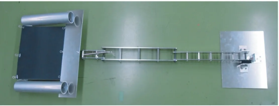
The platform’s mobility is provided by a self-made wheeled mobile base, which has differential drive steering with two powered wheels, including shaft encoders for motion tracking. The tread spacing is 60mm. Two caster wheels are further used for keeping the platform upright.Figure2.4 depicts the developed wheeled mobile base. Specifications for self-made wheeled mobile base is outlined in Table2.3.
T2.1: Specifications for PA10 robot arm
Model PA10-7C
Number of joint axes 7 Maximum distance between joints
930 mm
Self-weight 40 kg
Payload 10 kg
Operating speed Base(shoulder) axis : 28.5◦/s Elbow axis: 57◦/s Wrist axis: 180◦/s
Positioning repeata- bility
±0.1mm
Cleanliness Class 1 (not requiring inside pneumatic suction) Protective structure Dust and drip proof (IP54)
Built in tubing and cabling
Complete (till arm tip)built in cables available
T2.2: Specifications for motor driver of PA10 robot arm Function Velocity control/Torque(Current) control
Command Velocity command:±15bit (0.0002rad/sec/digit) (Output axis)
Rated torque for large-sized motor(S1,S2): 4.64Nm Input via ARCNET Rated torque for medium-sized motor(S3,E1): 2.00Nm
Rated torque for small-sized motor(E2,W1,W2):
4.64Nm
Motor power: DC 100V/8A Supply power Break power: DC 24V/4A
Control power: DC+5V/2A,DC+15V/1A,DC - 15V/1A,DC 24V/1A
2.2.3 Electric gripper
An electric gripper is attached to the PA-10 robot arm to handle objects during home service applications. When the gripper jaws close, the closing force of the gripper holds that object. This force is adjustable by variable voltage control of driving torque.
Specifications for electric gripper is outlined in Table2.4.
F. 2.2: Mitsubishi PA-10 robot arm with servo driver, and flowchart of Mitsubishi PA-10 four-layer control architecture.
T2.3: Specifications for self-made wheeled mobile base DC Servo motor (×2)
SuperV Series DC Servo motor from SANYO DENKI Co., Ltd
Model V406-011EL8
Rated speed 3000rpm
Rated output 60W
Rated torque 0.19Nm
Rated voltage 24V
Rated current 1.4A
Encoder resolution 1000p/r line-driver output Driving wheel (×2)
Ductile Iron rubber-tyred wheel from OKAMOTO KOUKI Co., Ltd
Model A130
Diameter 130mm
Load capacity 180kg
Caster (×2) from MISUMI Co., Ltd
Model CJH-75
2.2.4 A comprehensive sensor suite
A novel sensor suite concept is presented in the developed mobile manipulator platform, utilizing the synergies that exist between RFID sensors, tactile sensors, visual sensors, laser scanner sensors, force/torque sensors to provide a comprehensive sensor suite for a wide range of home service applications. RFID sensors and tactile sensors will be in- troduced in Chapter 3 and Chapter 4 respectively. Specifications for visual sensors (Mi- crosoft LifeCam NX6000, STH-MDCS2-VAR, SR4000), laser scanner sensor (SICK
F. 2.3: Motion range of PA-10 robot arm (Unit:mm).
Laser Measurement Sensor), and force/torque sensor (NITTA 6 DOF force/torque sen- sor) in the developed mobile manipulator platform are outlined below.
The Microsoft LifeCam NX6000 is a fair webcam that produces quality video at 640 x 480 or 800 x 600. Its specifications are outlined in Table2.5.
F. 2.4: Configuration of the mobile base.
T2.4: Specifications for electric gripper
Model HM-01 (Mitsubishi Electric Co., Ltd)
Driving DC Servo motor
Opening/closing stroke 0−60 mm
Grip force MAX 3.5kgf
Weight 600gf
The STH-MDCS2-VAR is a compact, low-power digital stereo head with an IEEE 1394 digital interface. It consists of two camera modules, each with a 1.3megapixel, progressive scan CMOS imager and a 1394 peripheral interface module, mounted in a rigid body. Its specifications are outlined in Table2.6.
The SR4000 is a measurement device that provides high-resolution 3D image data in real time. At the heart of the camera is an advanced sensor technology employing the time-of-flight (TOF) distance measurement principle. Infrared light from the cam- era’s internal lighting source is reflected by objects in the scene and travels back to the camera, where its precise time of arrival is measured independently by each of tens of thousands of sensor pixels. Its specifications are outlined in Table2.7.
The SICK Laser Measurement Sensor (LMS) 200 is an extremely accurate distance measurement sensor. The LMS 200 can easily be interfaced through RS-232 or RS- 422, providing distance measurements over a 180 degree area up to 80 meters away. Its specifications are outlined in Table2.8.
T2.5: Specifications for Microsoft LifeCam NX-6000
Model LifeCam NX-6000
Webcam Length 8.5cm (closed 6.8cm)
Webcam Width 3cm
Webcam Depth/Height 2cm Webcam Cable Length 18 inches
Motion Video 2.0 mega pixel (1600×1190 pixel) video Still Image 7.6 mega pixel (3200×2380 pixels) photos Field of View 71deg diagonal field of view
Zoom 18 3×digital zoom
The NITTA 6 DOF force/torque sensor is a control sensor to detect force with high accuracy in real time. Its specifications are outlined in Table2.9.
Sensors on the developed platform are added, removed, and moved based on the requirements of the task. For example, the current set for the object recognition and manipulation task (Chapter 3), shown in Fig. 2.5, comprises of a planar laser on the mobile base, an RFID equipment with its antenna installed on mobile base, and a camera on the arm. The SICK LMS laser on the mobile base is used for localization and motion planning. It is placed at a fairly standard location, at ankle height. It is connected to computer by RS232C. It has a scanning range of 180 degrees and with a distance resolution of 10mm in a range up to 80m. The web camera LifeCam NX-6000 by Microsoft is used on the arm. It is connected to computer by USB, with a resolution of 1600 × 1190 pixels. The image captured is processed in the computer by using OPEN CV, a high-level image processing and computer vision library developed by Intel Corporation. An XR480-JP RFID equipment by Symbol Co., Ltd. is used, which uses UHF band of 950MHz and can detect an ID tag in a range of 0−3m. It is connected to computer by Ethernet cable and supplies ID data as well as other specified data from computer. When the stand-up motion support task (Chapter 4) is considered, high- speed tactile sensors will be added in the design of an assist arm. As shown in Fig.2.6, such assist arm is then attached to the end of the manipulator arm and will be used for assisting the stand-up motion of elderly people. Meanwhile, the web camera on the arm will be removed.
T2.6: Specifications for VIDERE DESIGN Stereo Camera
Model STH-MDCS2-VAR
Imagers 1/2” format CMOS (Micron MT9M001)
1280×960 active area, Progressive scan, Color or monochrome
Digital Camera Specification
Version 1.30
Formats 1280×960, 640×480
8 bit monochrome or Bayer color pattern Frame Rates 3.75, 7.5, 15, 30 Hz 3.125, 6.5, 12.5, 25 Hz
Max 7.5 Hz at 1280x960 Exposure 1 line time to full frame
Gain 0−18 dB
Sensitivity 2.1V/lux-sec (monochrome)
S/N >45dB, no gain
Power <1W
Synchronization Internal: pixel-locked External: 60 us Lens 6.0 mm F 1.4 C mount included
3.5 mm, 8 mm, 12 mm and 16 mm lenses optional Size 1.5” high×2.6” long×1” deep (excluding lenses),
each module
Weight Camera module: 3.7 oz Cameras and mounting bar: 15.5 oz Typical weight with lenses: 18.7 oz
Stereo Baseline 5 to 20 cm
SVS software Linux kernel 2.4, 2.6 MSW 98SE, ME, 2000 and XP Environmental 0−40◦C,<90% humidity (noncondensing)
2.3 Perception and Control Architectures
The developed platform uses a PC/AT compatible machine with a Pentium 4 3.0GHz CPU. It is running a real-time operation system ART-Linux or Windows OS. The main perception and control architectures for the cases of the object recognition and manip- ulation task and the stand-up motion support task are depicted in Fig.2.7and Fig.2.8, respectively.
T2.7: Specifications for MESA IMAGING SR4000 3D Camera
Model SR4000
Pixel Array Size 176 (h) x 144 (v), QCIF
Field of View 43.6◦(h) x 34.6◦(v), standard field of view cameras or 69◦(h) x 56◦(v), wide field of view cameras Detection Range 0.1−5.0 m, ranges are radial distances Absolute Accu-
racy
±10 mm(typ.), at 99% target reflectivity, over calibrated range
Repeatability <5 mm, distance 2m Maximum Frame
Rate
50 FPS Communication
Interface
USB Illumination
Wavelength
850 nm, central wavelength
Dimensions 65×65×68 mm
Output Data Cartesian XYZ coordinates, reflection intensity
2.4 Summary
In this chapter, a general purpose mobile manipulation platform has been presented to enable the exploration of new methods for perception and manipulation in home en- vironments. The developed platform characterizes both redundant kinematic degrees of freedom and a comprehensive sensor suite. Thus, it provides an adequate level of competency to address various mobile manipulation challenges, where both adequate sensorimotor capabilities and acquisition and fusion of a variety of exteroceptive infor- mation are required.
T2.8: Specifications for SICK Laser Measurement Sensor LMS200
Model LMS200
Laser class 1 (EN/IEC 60825-1), eye-safe
Field of view 180◦
Scanning frequency 75 Hz
Operating range 0−32m (depending on resolution settings) Resolution 1mm (1cm, or 10cm also available)
Angular resolution 0.5◦or 1◦
Systematic error ±15mm
Statistical error 5mm
MTBF 80,000 hours
Interface RS-232 integrated with robot power and onboard computer. Laser is also capable of RS-422.
Data transmission rate 9.6 or 19.2 kBaud Operating voltage ≤24VDC±15%
Power consumption 30 W
Enclosure housing Aluminum diecast, IP 65 rating
Dimensions 156mm×155mm×210mm
Weight 4.5 kg
Vibration and shock resis- tance rating
IEC 68 Ambient operaing tem-
perature
0−50◦C Storage temperature −30−70◦C Permissible relative hu-
midity
90% (non-condensing)
T2.9: Specifications for NITTA Force Sensor IFS-67M25A 50-I40
Model IFS-67M25A 50-I40
Rated values Fx, Fy 200N, Fz 400N, Mx-Mz 13Nm
Outside diameter 67mm
Height 25mm
Weight 180g
Power voltage DC±7−15V
Output voltage DC±5V
Operating temperature 0−45◦C
F. 2.5: Hardware configuration for object recognition and manipulation.
F. 2.6: Hardware configuration for stand-up motion support.
F. 2.7: Perception and control architecture for object recognition and manipulation.
F. 2.8: Perception and control architecture for stand-up motion support.