PAPER
Parallel Peak Cancellation Signal-Based PAPR Reduction Method Using Null Space in MIMO Channel for MIMO-OFDM
Transmission ∗
Taku SUZUKI†, Mikihito SUZUKI†,Members,andKenichi HIGUCHI†a),Senior Member
SUMMARY This paper proposes a parallel peak cancellation (PC) pro- cess for the computational complexity-efficient algorithm called PC with a channel-null constraint (PCCNC) in the adaptive peak-to-average power ratio (PAPR) reduction method using the null space in a multiple-input multiple-output (MIMO) channel for MIMO-orthogonal frequency division multiplexing (OFDM) signals. By simultaneously adding multiple PC sig- nals to the time-domain transmission signal vector, the required number of iterations of the iterative algorithm is effectively reduced along with the PAPR. We implement a constraint in which the PC signal is transmitted only to the null space in the MIMO channel by beamforming (BF). By do- ing so the data streams do not experience interference from the PC signal on the receiver side. Since the fast Fourier transform (FFT) and inverse FFT (IFFT) operations at each iteration are not required unlike the previous al- gorithm and thanks to the newly introduced parallel processing approach, the enhanced PCCNC algorithm reduces the required total computational complexity and number of iterations compared to the previous algorithms while achieving the same throughput-vs.-PAPR performance.
key words: OFDM, PAPR, MIMO, beamforming, clipping and filtering, peak cancellation, computational complexity reduction, parallel process
1. Introduction
The combination of massive multiple-input multiple-output (MIMO) [1], [2], in which a base station transmitter em- ploys a very large number of antennas, using beamform- ing (BF) and orthogonal frequency division multiplexing (OFDM) signals offers wide-coverage enhanced mobile broadband such as 5G. However, the problem of lowering the peak-to-average power ratio (PAPR) of massive MIMO- OFDM signals must be addressed because of the linearity requirement on the transmitter power amplifier for each of the huge number of antennas. In massive MIMO, the high PAPR of OFDM signals may also be further enhanced due to the variation in the transmission power levels among the transmitter antennas caused by the BF process.
Numerous techniques have been proposed to reduce the PAPR[3]. The clipping and filtering (CF) method[4]–
[6]limits the peak envelope of the input signal in the time Manuscript received August 5, 2020.
Manuscript revised October 19, 2020.
Manuscript publicized November 20, 2020.
†The authors are with the Graduate School of Science and Technology, Tokyo University of Science, Noda-shi, 278-8510 Japan.
∗The material in this paper was presented in part at the 91st IEEE Vehicular Technology Conference (VTC2020-Spring), Antwerp, Belgium, 2020.
a) E-mail: higuchik@rs.tus.ac.jp DOI: 10.1587/transcom.2020EBT0008
domain to a predetermined value using a clipping opera- tion. However, the distortion caused by the amplitude clip- ping is viewed as another source of noise. The CF method can preserve frequency efficiency, but the clipping opera- tion causes in-band interference that cannot be reduced by filtering. References[7]and[8]propose the selected map- ping (SLM) method and the partial transmit sequence (PTS) method, respectively. Both the SLM and PTS methods re- duce the PAPR by multiplying symbols by each phase fac- tor, which minimizes the PAPR of the input signal in the time domain. These methods require a high level of com- putational complexity when the number of phase factors is increased. References[9]and[10]investigate PAPR reduc- tion based on the SLM or PTS method considering the arti- ficial bee colony (ABC) algorithm to decrease the high level of computational complexity. The tone reservation (TR) method[11]separates the total number of subcarriers into two parts: the subcarriers for data transmission and those for PAPR reduction signal transmission. The TR method does not interfere with the data symbols but reduces the fre- quency efficiency.
The PAPR reduction problems in MIMO-OFDM sig- naling have also been discussed extensively in literature.
References [12] and[13] assume the case of no BF. Ref- erence [14]assumes eigenmode MIMO-based BF and ap- plies the SLM and PTS methods. The use of the SLM or PTS method degrades the achievable error rate or through- put of the MIMO-OFDM signal due to a reduced channel coding gain especially in a multiuser MIMO scenario. In downlink massive MIMO, the number of base station trans- mitter antennas is in general much larger than that of user terminal receiver antennas. Under this assumption, joint op- timization of BF, OFDM modulation, and PAPR reduction is investigated in [15]. The tone reservation-based PAPR reduction scheme is investigated in [16]. This kind of ap- proach reduces the frequency efficiency since a part of the transmission bandwidth cannot be used for data transmis- sion. Reference[17]proposes a PAPR reduction method in which some of the transmitter antennas are exclusively used for PAPR reduction in order to remove the in-band interfer- ence due to the PAPR reduction signal on the receiver side.
However, the method in[17]reduces the BF gain of the data streams since the number of transmitter antennas used for the transmission of data streams is reduced.
Members of our research group reported on an adap- Copyright c2021 The Institute of Electronics, Information and Communication Engineers
tive PAPR reduction method using the null space in a chan- nel for MIMO-OFDM signals[18]–[20]. This method re- stricts the peak reduction signal transmitted to only the null space in the given MIMO channel to suppress the degra- dation in the transmission quality of the data streams that would otherwise be caused by the interference from the in- band peak reduction signal. Since all transmitter anten- nas are fully utilized for transmitting the data streams, the achievable BF gain of the reported method is higher than that for the method in[17]. It is expected that the effect of the adaptive PAPR reduction method using the null space in the MIMO channel will increase in a massive MIMO sce- nario, since the dimensions of the null space increase. Mem- bers of our research group also investigated the performance of this method in a massive MIMO transmission scenario [21],[22]. We note that[23]investigated the unused beam reservation-based PAPR reduction method, which is similar to the use of null space in a MIMO channel as originally reported in[18]–[20].
In previous investigations by members of our research group[18]–[20], the adaptive PAPR reduction is actualized using an iterative algorithm in which the CF operation and the projection of the peak reduction signal generated by CF onto the null space in the MIMO channel are applied at each iteration. In the following, this method is referred to as the CF followed by the channel-null constraint (CFCNC). Since CFCNC requires the fast Fourier transform (FFT) and in- verse FFT (IFFT) operations at each iteration and peak re- growth occurs due to the filtering of out-of-band radiation and the channel null constraint in the peak reduction signal, the required computational complexity is relatively high.
We recently reported a computationally efficient algo- rithm for the adaptive PAPR reduction method using the null space in a MIMO channel in[24]. The reported algorithm is based on the peak cancellation (PC) signal method origi- nally proposed in[25]and[26]and a channel-null constraint is additionally applied. Hereafter, this algorithm is referred to as the PC with a channel-null constraint (PCCNC). The PC signal is designed so that it has a single dominant peak and satisfies the requirement for out-of-band radiation. By directly adding the PC signal to the time-domain transmis- sion signal at each transmitter antenna, the PAPR is reduced.
PCCNC performs PC signal-based PAPR reduction jointly considering all transmission signals for all antennas. Thus, the PC signal is constructed in vector form. By setting the BF vector of the PC signal orthogonal to the MIMO chan- nel, i.e., the BF vector is restricted within the null space in the MIMO channel, the interference to the data streams is eliminated on the receiver side. Since the FFT and IFFT op- erations are not required at each iteration, the computational complexity of PCCNC is lower than that for conventional CFCNC. However, although PCCNC in [24] significantly reduces the computational complexity, the required number of iterations is rather large, thus a long processing delay may be required since only a single peak in the transmission sig- nals is suppressed at each iteration.
To address the problem, we propose a new PCCNC
in which a parallel peak suppression process at each itera- tion is introduced in order to suppress multiple peaks in the transmission signals at each iteration. By simultaneously adding multiple PC signal vectors to the time-domain trans- mission signal vector, the number of iterations is effectively reduced. We should consider the fact that when the differ- ence between two target timings of peak signals in a paral- lel peak suppression process is excessively small, the peak regrowth may be caused by the effect of the superposition of the main and side lobes of multiple PC signals. To ad- dress this issue, the newly proposed PCCNC with parallel processing restricts the minimum difference between multi- ple target timings of peak signals. We show that the newly proposed PCCNC reduces both the required number of iter- ations and total computational complexity compared to the conventional CFCNC while achieving the same throughput- vs.-PAPR performance. We note that the contents of this paper are based on [27], but include enhanced evaluation and discussions.
The remainder of the paper is organized as follows.
First, Sect. 2 briefly describes the principle of the adaptive PAPR reduction method using the null space in the MIMO channel and the conventional CFCNC. Section 3 describes the newly proposed PCCNC. Section 4 presents numerical results based on computer simulations. Finally, Sect. 5 con- cludes the paper.
2. Adaptive PAPR Reduction Method Using Null Space in MIMO Channel and Conventional CFCNC Algo- rithm
2.1 Principle of Adaptive PAPR Reduction Method Here, we briefly explain the principle behind the adaptive PAPR reduction method using the null space in a MIMO channel [18]–[20]. In general, when PAPR reduction is applied to each transmitter antenna independently, the in- terference component created by the peak reduction signal appears in the transmission frequency band. The adaptive PAPR reduction method using the null space in the MIMO channel limits the transmission of the interference compo- nent generated through the PAPR reduction process to just the null space in the MIMO channel. This results in mitigat- ing the throughput reduction due to the interference inherent in PAPR reduction.
The numbers of transmitter and receiver antennas are denoted as N and M, respectively. We assume N > M.
Therefore, the number of data streams spatially multiplexed isM. In this paper, we assume that the MIMO channel is not frequency-selective for simplicity. TheM×N-dimensional channel matrix is denoted asH. The number of subcarriers in the OFDM signal is denoted asK.
Since N is greater than M, we have N ×(N −M)- dimensional matrix Vthat satisfiesHV = O. We assume that all theN−Mcolumn vectors inVare orthonormalized.
MatrixVcorresponds to the null space in MIMO channelH.
The frequency-domainN-dimensional effective data trans-
mission signal vector at some subcarrierk after BF is de- noted asxfreq,k. After the PAPR reduction process is applied at each transmitter antenna, the frequency-domain transmis- sion signal vector at subcarrierkcan be represented as
˜xfreq,k=xfreq,k+∆k. (1)
Here,∆kis the in-band peak reduction signal vector (inter- ference component to the data stream) added by the PAPR- reduction operation. The adaptive PAPR reduction method using the null space in the MIMO channel limits the trans- mission of the interference component for PAPR reduction purposes to only the null space in the MIMO channel by BF.
More specifically, if∆kcan be represented with an (N−M)- dimensional vector, ek, as∆k = Vek, the signal vector ob- served on the receiver side is represented as
H˜xfreq,k=H(xfreq,k+∆k)=Hxfreq,k+HVek=Hxfreq,k. (2) Since the in-band peak reduction signal is beamformed by V, it does not appear on the receiver side of M antennas as HVek = 0. Therefore, the PAPR is reduced while the throughput degradation is alleviated.
2.2 Conventional CFCNC
The iterative CFCNC algorithm alternately repeats the PAPR reduction process using the CF operation and restores the restrictions on the peak reduction signal components for actualizing the adaptive PAPR reduction method using the null space in a MIMO channel. Figure 1 shows a block dia- gram of CFCNC.
In the following, details of the CFCNC process at thej- th iteration (j=1, . . . ,J) are described. The number of iter- ations is denoted asJ. Theekvector generated at the j-th it- eration is denoted ase(kj). At the j-th iteration, the frequency- domain transmission signal vector after BF at subcarrierk, x(freq,kj) , is obtained as
x(freq,kj) =xfreq,k+Ve(kj−1). (3) As the initial setting, e(0)k is set to 0. Thus, we assume x(1)freq,k=xfreq,k.
At each transmitter antenna, the IFFT is applied to the frequency-domain transmission signal sequence, in which the components of x(freq,kj) for all subcarriers are collected, and the corresponding time-domain transmission signal se- quence is obtained for each transmitter antenna.
Clipping is independently applied to the time-domain transmission signal sequence based on a predetermined threshold. Then, filtering is performed on the clipped sig- nal. In this paper, we assume that filtering to remove the out-of-band radiation caused by the clipping is performed by setting the signal strength of the frequency component corresponding to the out-of-band radiation to zero in the
Fig. 1 Block diagram of CFCNC.
frequency domain by applying the FFT to the clipped time- domain signal. After the above CF process, the frequency- domain transmission signal vector after BF, x(freq,kj) , is as- sumed to be converted as
˜x(freq,kj) =xfreq,k+∆(kj). (4) Here, ∆(kj) is the in-band peak reduction signal vector ob- served at the j-th iteration, which causes interference to the data stream.
To remove the interference component to the data stream, the last step of the process at the j-th iteration re- stores the restriction that the peak reduction signal is trans- mitted only to the null space in the MIMO channel. Thus, e(kj)is updated as
e(kj)=VH(˜x(freq,kj) −xfreq,k)=VH∆(kj). (5) This is the projection of the peak reduction signal to the null space in the MIMO channel.
CFCNC repeats the above process until jreachesJ. At the last iteration, ˜x(J)freq,k is transmitted. CFCNC actualizes the adaptive PAPR reduction method using the null space in a MIMO channel by repeating the CF operation and appli- cation of the channel-null constraint on the PAPR reduction signal. However, since the clipping process is performed in the time domain and the filtering process is performed in the frequency domain, the FFT and IFFT operations are re- quired at each iteration as shown in Fig. 1. In addition, peak regrowth occurs due to the filtering of out-of-band radiation and the channel null constraint in the peak reduction signal.
Therefore, the computational complexity of CFCNC is rela- tively high.
3. Proposed PCCNC with Parallel Processing
This section describes the proposed computationally effi- cient PCCNC algorithm with parallel processing for the adaptive PAPR reduction method using the null space in the MIMO channel. This algorithm is an extension of the per- antenna PC signal-based PAPR reduction method (PAPC) in[25]and[26]. PCCNC performs PC signal-based PAPR reduction jointly considering all transmission signals for all antennas. Thus, the PC signal is constructed in vector form.
The PC signal vector is designed so that it is only transmit- ted to the null space in the MIMO channel and satisfies the out-of-band radiation requirement. By directly adding the PC signal vector to the time-domain transmission signal, the PAPR is reduced while the interference to the data streams
Fig. 2 Basic time-domain signal,g[t].
is eliminated on the receiver side. Since FFT and IFFT op- erations are not required at each iteration, it is expected that the computational complexity will be reduced compared to that for CFCNC.
The basic time-domain signal,g[t], which is used to generate the PC signal vector, is given as
g[0]... g[F−1]
=FH
λ[0]... λ[F−1]
, (6)
where
λ[f]=λ[F−f]=
√ F
K (1+α), 0≤ f ≤1−α1+α·K2
(1+α)√ F 2K
n1−sin(1+α)π
αK
f −2(1K+α)o
, 1−α1+α ·K2 < f ≤K2
0, K2 < f ≤ F2
.
(7) Here,trepresents the discrete time index andt=0, . . . ,F− 1, whereF(F>K) is the number of FFT/IFFT points. Ma- trixFis theF×F-dimensional FFT matrix whose (m,n)-th element ise−j(2π(m−1)(n−1))/F/√
F. Termλ[f] and λ[F− f] as a function of frequency index f (f =0, . . . ,F/2) is the spectrum ofg[t] that corresponds to the frequency transfer function of the impulse signal. Termλ[f] in (7) is defined based on the raised-cosine filter with the roll-offfactor of α(0 ≤ α ≤ 1) in this paper. We note that this paper fo- cuses on baseband signaling, and specifies that the out-of- band radiation requirement is zero for the sake of simplicity.
Therefore, the bandwidth ofg[t] is fixed toKsubcarriers ir- respective ofα. Whenα=0.0,λ[f] is an ideal rectangular function andg[t] becomes a sinc function. Figures 2 and 3 showg[t] and its spectrum in the frequency domain, re- spectively, when K = 64 and F = 256. For any α, g[t]
has its maximum peak amplitude of 1.0 att =0 as shown in Fig. 2 and satisfies the out-of-band radiation requirement of zero for the baseband transmission signal as shown in Fig. 3. Asαis set larger, the main lobe of the maximum peak att =0 becomes wider while the time-domain ripple (side lobe) level decreases more quickly. These properties may affect the peak regrowth issue after PC signal addition and this is quantitatively evaluated in Sect. 4. Whenα=0.0, the width of the main lobe of the maximum peak att=0 is
±F/Kdiscrete times (samples).
Fig. 3 Spectrum ofg[t] in frequency domain.
Fig. 4 Block diagram of proposed PCCNC.
Hereafter, the N-dimensional time-domain transmis- sion signal vector before PAPR reduction at timetis denoted asx[t], whosen-th element isxn[t].
x[t]=[x1[t] · · · xN[t]]T. (8) The time-domain transmission signal vector at the j-th iteration of PCCNC is denoted as x(j)[t] = [x(1j)[t] · · · xN(j)[t]]T. We assumex(1)[t]=x[t].
In the following, details of the PCCNC process at the j-th iteration are described. Figure 4 shows a block diagram of PCCNC. The proposed PCCNC tries to suppress in par- allelL(L ≤F) peaks observed at differentLtime indexes, τ(1j), . . . , τ(Lj), at each iteration for a faster processing time.
We note that this is different from the initial work on PC- CNC in[24].
First, Ltarget time indexes for PAPR reduction at the j-th iteration are determined based onx(j)[t]. This is basi- cally done by finding Ltimings where theL-highest peaks are observed. However, as is presented hereafter, when the difference between two target time indexes is excessively small, the negative impact of the superposition of the main lobe of the PC signals (shown in Fig. 2) on the peak regrowth after the addition of multiple PC signals must be addressed.
To address this issue, we apply a restriction to the minimum time difference, δ, between the L selected target time in- dexes. Parameterδ(δ >0) controls the minimum difference betweenτ(lj), . . . , τ(Lj).
The selection ofτ(1j), . . . , τ(Lj) is performed as follows.
First, the time index, where x(nj)[t] has the maximum am- plitude for all n andt, is selected asτ(1j). After that, τ(lj) (l=2, . . . ,L) is determined in sequential manner as τ(lj)=arg max
t
maxn
|x(nj)[t]|
for t∈ {0, . . . ,F−1}\S
l0=1,...,l−1{τ(l0j)−δ, . . . , τ(l0j)+δ}. (9)
Then, all the l-th (l = 1, . . . ,L) PC signal vectors, p(lj)[t], which are represented in the form of (10), are added tox(j)[t] to reduce simultaneously the peak power observed at theLdifferent timing indexes.
p(lj)[t]=−w(lj)gh t−τ(lj)i
. (10)
x(j+1)[t]=x(j)[t]+
L
X
l=1
p(lj)[t]. (11) Basic signalg[t] has its maximum peak amplitude of 1.0 at t = 0. Thel-th PC signal vector,p(lj)[t], is generated from theτ(lj)-time-shifted version ofg[t],−g[t−τ(lj)], by applying BF with the BF vector ofw(lj). By addingp(lj)[t] to x(j)[t], the peak power observed att = τ(lj) is suppressed by the peak signal portion ofg[0], while the impact of adding the PC signal to the other timing is mitigated.
An important component of the PC signal vector,p(lj)[t]
is its BF vectorw(lj). TheN-dimensional vectorw(lj) should lie within the null space in the MIMO channel. PC signal vectorp(lj)[t] beamformed byw(lj)satisfies the requirements for the zero interference to the data streams. This is because the PC signal is transmitted to only the null space in the given MIMO channel and does not appear on the receiver side. In this paper,w(lj)is calculated as
˜ w(lj)=h
w˜(l,1j) · · · w˜(l,Nj)iT
w˜(l,nj) =
xn(j)[τ(lj)]−Athejθ(nj)[τl(j)], |x(nj)[τ(lj)]|>Ath
0, Otherwise
. (12)
w(lj)=VVHw˜(lj). (13) Here,θn(j)[τ(lj)] is the phase ofxn(j)[τ(lj)]. TermAthis the pre- determined amplitude threshold for PAPR reduction. Vector
˜
w(lj) is an ideal peak reduction vector in the sense that if vectorw˜(lj)calculated in (12) is used asw(lj)in (10), the am- plitude levels of the transmission signals for allNantennas at timeτ(lj) (thus,
x(nj)[τ(lj)]
for alln) can simultaneously be set equal to or lower than Ath. However, vectorw˜(lj) has a component that is orthogonal to the null space in the MIMO channel (thus,H ˜w(lj) ,0), which causes interference to the data streams. Therefore,w˜(lj)is projected onto the null space in MIMO channelVto generatew(lj)using (13).
PCCNC repeats the above process until j reaches J.
Since the FFT and IFFT operations are not needed at each iteration as shown in Fig. 4, PCCNC is expected to achieve a lower level of computational complexity and number of it- erations than that for the conventional CFCNC. In addition, PCCNC with parallel processing reduces the number of iter- ations (in other words, the processing delay time) compared to that for PCCNC without parallel processing.
4. Numerical Results
4.1 Simulation Parameters
The number of transmission antennas,N, is set to 64 or 128.
The number of receiver antennas,M, is fixed at 4. The num- ber of subcarriers, K, is 64. We mainly use the number of FFT/IFFT points,F, of 256, which corresponds to theF/K of 4-times oversampling in the time domain in order to mea- sure a satisfactorily accurate PAPR level[28]. However, to evaluate in detail the relationship between an appropriate δ and L by further increasing the time resolution, we as- sume theFof 1024 (16-times oversampling) only in Fig. 7.
For evaluation generality, we assume that the signal con- stellation of each subcarrier follows an independent stan- dard complex Gaussian distribution. Assuming multiuser MIMO, zero-forcing BF is applied. As the channel model, we assume flat Rayleigh fading, which is independent be- tween transmitter antenna branches and between receiver antenna branches. The signal-to-noise ratio (SNR) is set to 10 dB.
As the adaptive PAPR reduction method using the null space in the MIMO channel, conventional CFCNC and the proposed PCCNC are tested. As a per-antenna independent PAPR reduction method, the per-antenna CF (PACF) and PAPC are also tested for comparison. PAPC is assumed to employL-parallel processing per iteration as in PCCNC. For all methods, the number of iterations, J, is parameterized.
In PAPC and PCCNC, L,δ, andαare also parameterized.
In PCCNC, after Jiterations, PAPC is assumed to be per- formed with Jadd = J/10 iterations in order to achieve a lower PAPR at the cost of reduced throughput for the pur- pose of clear comparison to CFCNC.
The power threshold,Pth =|Ath|2, in the PAPR reduc- tion process is defined as the signal power threshold nor- malized by the signal power per antenna averaged over the channel realizations. The PAPR is defined as the ratio of the peak signal power to the average signal power across all the transmitter antennas per OFDM symbol. The sum through- put ofMstreams (users) is calculated based on the Shannon formula taking into account the Bussgang theorem[29].
4.2 Simulation Results
First, we evaluate the effect of the restriction on the mini- mum time difference,δ, for the proposed PCCNC with par- allel processing. Figure 5 shows the average PAPR as a function ofδfor PCCNC withNas a parameter. Parameters JandLare set to 10 and 32, respectively. The roll-offfactor, α, of the PC signal is set to 0.0. ThresholdPthis set to 3 dB and 7 dB. Both theNof 64 and 128 are evaluated. WhenPth
is 7 dB, the average PAPR is almost constant regardless of δ. However, whenPthis 3 dB, the average PAPR of PCCNC withδof 1 is very high. This observation does not depend onN. This is due to the peak regrowth caused by the super- position of the main lobe of the PC signal amongL-parallel
Fig. 5 Average PAPR as a function ofδwithNas a parameter.
processes. Furthermore, the average PAPR increases when using an excessively largeδ. This is because in this case the degrees of freedom in selectingLtarget peaks are limited.
Figures 6 and 7 show the average PAPR as a function ofδfor PCCNC withLas a parameter. Figure 6 assumes the Fof 256 that corresponds to the oversampling factorF/Kof 4 and is the same as in the other evaluations. In Fig. 7,Fis set to 1024 so that the oversampling factor is increased to 16 and the time resolution is 4-times finer than that in Fig. 6 in order to measure precisely the impact ofLon the bestδ value. TermsN,J, andαare set to 128, 10, and 0.0, respec- tively. Threshold Pth is set to 3 dB. Figures 6 and 7 show that the use of an excessively smallδresults in degradation in the achievable PAPR. This is because the probability of the peak regrowth caused by theL-parallel process increases due to the superposition of the main lobe of multiple PC sig- nals added in parallel to the transmission signal at each iter- ation. This degradation is significant whenLis large. When using an excessively largeδ, the PAPR increase is also ob- served especially when L is large. This is because in this case the degrees of freedom in selectingL target peaks is limited and PCCNC must perform PC-signal addition to the limited number of peak signals, which is less thanL, at each iteration. Figure 7 shows that asLis increased the impact of theδselection on the achievable PAPR becomes clearer and the bestδvalue decreases. This is due to the tradeoffbe- tween the negative impact of the superposition of the main lobe of multiple PC signals and the degrees of freedom in selectingLtarget peaks. With an appropriate choice forδ, the achievable PAPR is reduced asLis increased thanks to the parallel processing at each iteration.
However, the variations in the bestδvalues for different Lsettings are not significant. When we assume a practical oversampling factor,F/K, of 4 usingFof 256 as in Fig. 6, the best δ is approximately 3 irrespective of the L value.
This corresponds to 75% of the main lobe width of the main peak for a PC signal withαof 0.0, i.e.,±F/K=4.
Next, we evaluate the impact of the roll-offfactor,α, of the PC signal on the average PAPR as a function ofδ.
Fig. 6 Average PAPR as a function ofδwithLas a parameter (F/K=4).
Fig. 7 Average PAPR as a function ofδwithLas a parameter (F/K= 16).
Figure 8 shows the average PAPR as a function ofδwith α as a parameter. TermsN, J, L, and Pth are set to 128, 10, 32, and 3 dB, respectively. The overall performance ten- dency is the same for all testedαvalues. Asαis increased, the PAPR degradation at δ = 2 is slightly increased. The reason for this can be understood in Fig. 9. Figure 9 shows the maximum interference power levels of a PC signal ob- served outside the restrictedδ-time durations, which is nor- malized by the peak power ofg[0]. This interference level is a source of peak regrowth. The main lobe of the PC sig- nal becomes wider asαis increased as shown in Fig. 2. The PC-signal interference becomes higher whenαis large for a relatively smallδregime, although the ripple (side lobe) level decreases more quickly, which corresponds to a lower interference level for largeδvalues. In conclusion, the best δis approximately constant for variousαsettings assuming a practical oversampling factor, and α = 0.0 achieves the best PAPR performance.
Figure 10 shows the average PAPR as a function of J for PCCNC withδas a parameter. TermsN,α,L, andPth
are set to 128, 0.0, 32, and 3 dB, respectively. Theδvalues
Fig. 8 Average PAPR as a function ofδwithαas a parameter.
Fig. 9 PC-signal interference power relative to main peak as a function ofδwithαas a parameter.
of 1, 3, and 10 are tested. When Jis increased, the aver- age PAPR of PCCNC withδ=1 is significantly increased.
Meanwhile, asδ is increased to 3 or 10, the reduction in the average PAPR is enhanced. This confirms that the re- striction on the minimum time difference,δ, helps PCCNC with parallel processing work well. When comparing PC- CNC usingδ=3 to that usingδ=10, PCCNC usingδ=3 reduces the required number of iterations for achieving the same average PAPR than that forδ = 10. This is because by setting the bestδvalue, PCCNC with parallel processing achieves peak reduction more efficiently at each iteration.
Figures 5–10 show that theδof 3 withα= 0.0 is the best for the proposed PCCNC with parallel processing from the viewpoint of the achievable PAPR performance under the assumed simulation conditions. In the following evaluation, αandδare set to 0.0 and 3, respectively, for PAPC and PC- CNC.
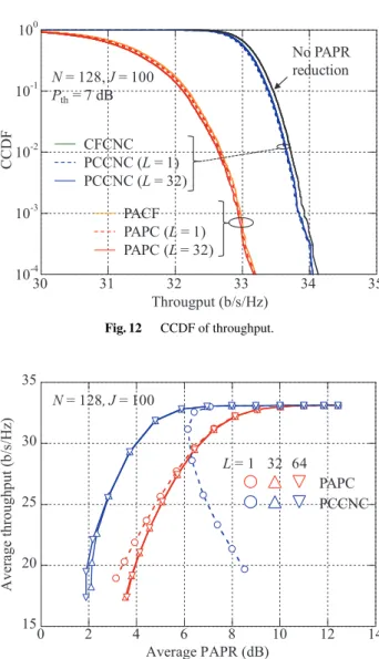
From here, we compare the proposed PCCNC with conventional CFCNC and the per-antenna independent PAPR reduction approach such as PACF and PAPC. Fig- ures 11 and 12 show the complementary cumulative distri- bution function (CCDF) of the PAPR and throughput, re-
Fig. 10 Average PAPR as a function of number of iterations,J.
Fig. 11 CCDF of PAPR.
spectively.Nis set to 128.PthandJare set to 7 dB and 100, respectively. The Lof 1 and 32 are evaluated. The PAPR distributions of all PAPR reduction methods are quite com- parable regardless ofL. The throughput levels for CFCNC and PCCNC (shown in overlapped green and blue lines) are very close to that without PAPR reduction and much better than those for PACF and PAPC (shown in overlapped or- ange and red lines), irrespective of L. This is because the peak reduction signal is concentrated in the null space in the MIMO channel in CFCNC and PCCNC; therefore, it does not interfere with the data stream on the receiver side. This confirms that PCCNC with parallel processing works well.
Figure 13 shows the average throughput as a function of the average PAPR for PCCNC and PAPC withLas a pa- rameter. The relationship between the average PAPR and average throughput is varied by changing thePth value for the PCCNC and PAPC methods. NandJare set to 128 and 100, respectively. For PCCNC, the achievable throughput- vs.-PAPR performance for L = 1 is degraded compared to that for L = 32 or 64. This is because J = 100 and Jadd=10 in PCCNC are insufficient to suppress all peaks in
Fig. 12 CCDF of throughput.
Fig. 13 Average throughput as a function of average PAPR for PCCNC and PAPC withLas a parameter.
the transmission signal whenLis 1 since only a single peak is suppressed per iteration. Regardless ofL, PAPC achieves comparable throughput-vs.-PAPR performance in the high PAPR region. Meanwhile, the achievable performance of PAPC is degraded in the low PAPR region when L is in- creased to 32 or 64. This is becauseLPC signals are added independently to each transmitter antenna per iteration and the in-band interference from the PC signals is increased as L becomes large. This degradation is not observed in PC- CNC since the interference to the data streams is eliminated on the receiver side.
Figure 14 shows the average throughput as a func- tion of the average PAPR for the respective PAPR reduc- tion methods withN as a parameter. The relationship be- tween the average PAPR and average throughput is varied by changing thePthvalue for the respective PAPR reduction methods. JandLare set to 100 and 32, respectively. When using the per-antenna PAPR reduction approaches such as PACF and PAPC, the degradation in the throughput accom- panying the reduction in the PAPR is large. This degradation
Fig. 14 Average throughput as a function of average PAPR for respective PAPR reduction methods withNas a parameter.
Fig. 15 Average throughput as a function of number of iterations,J.
is remarkable especially when N is large. This is because the interference from the peak reduction signal becomes a dominant factor in the degradation in the throughput when N is large as the increased BF gain diminishes the impact of receiver noise. On the other hand, the adaptive PAPR reduction method using the null space in the MIMO chan- nel employing CFCNC and PCCNC mitigates the degrada- tion in the throughput caused by the reduction in the PAPR.
Focusing on PCCNC and CFCNC, PCCNC achieves bet- ter throughput-vs.-PAPR performance than CFCNC. This is due to circumventing the peak regrowth caused by the filter- ing of out-of-band radiation in CF-based approach.
Figure 15 shows the average throughput as a function of Jfor a given PAPR requirement. The required average PAPR is set to 7 dB. Both the N of 64 and 128 are evalu- ated. Lis parameterized from 1, 32, to 64. Regardless of N, the required number of iterations of PCCNC withL=1 for achieving the same throughput is much larger than that for CFCNC. However, as Lis increased to 32 or 64, PC- CNC reduces the required number of iterations compared to that for CFCNC. This is becauseLpeak signals can be sup-
Table 1 Number of real multiplications per iteration for respective PAPR reduction methods.
pressed in parallel by multiple PC signals at each iteration.
Therefore, PCCNC with parallel processing reduces the re- quired number of iterations and mitigates the delay time of the PAPR reduction process compared to CFCNC and PC- CNC without parallel processing while achieving compara- ble throughput-vs.-PAPR performance levels. We note that PAPC withL-parallel processing achieves a better tradeoff than PACF as well.
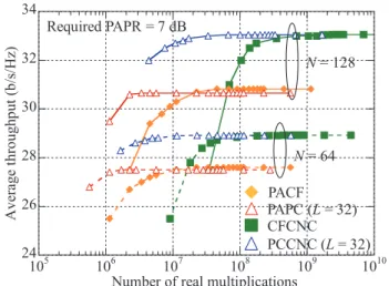
Since the required calculation cost per iteration is dif- ferent among all the evaluated methods, in the following we compare the throughput-vs.-PAPR performance levels of all methods for the same computational complexity. In this pa- per, we use the required number of real multiplications for each method to evaluate the computational complexity. Ta- ble 1 gives the number of real multiplications per iteration required for the respective PAPR reduction methods. The number of real multiplications is a function ofN,M,F, and L.
Based on Table 1, Fig. 16 shows the average through- put as a function of the number of real multiplications of PCCNC and PAPC for a given PAPR requirement with L as a parameter. The required average PAPR is set to 7 dB.
The relationship between the number of real multiplications and the average throughput is varied by changingJfor the respective PAPR reduction methods. PCCNC withL = 32 reduces the computational complexity required for achiev- ing the same PAPR compared to PCCNC withL =1. This is mainly because the number of power measurement pro- cesses that is conducted at each iteration is reduced asLis increased since the number of iterations is decreased thanks to the parallel peak reductions. PCCNC with L = 64 in- creases the computational complexity levels compared to that forL =32. This may be because an excessively high- parallel processing results in inefficient peak reduction due to the peak regrowth caused by the superposition of multi- ple PC signals. We confirm based on Figs. 15 and 16 that the use of appropriateLparallel processing in PCCNC con- tributes to not only a reduction in the number of iterations
Fig. 16 Average throughput as a function of number of real multiplica- tions of PCCNC and PAPC withLas a parameter.
Fig. 17 Average throughput as a function of number of real multiplica- tions for respective PAPR reduction methods.
but also a reduction in the computational complexity.
Figure 17 shows the average throughput as a function of the number of real multiplications of the respective PAPR reduction methods for the required average PAPR of 7 dB.
L is set to 32 for PCCNC and PAPC. When we focus on PCCNC and CFCNC, PCCNC achieves a better tradeoffbe- tween the throughput and computational complexity than CFCNC. The reduction in computational complexity using PCCNC compared to that for CFCNC is enhanced as N is increased. For example, when the target throughput is 32 b/s/Hz at the PAPR of 7 dB withN =128, PCCNC with L = 32 reduces simultaneously the number of iterations and computational complexity by approximately 1/3 and 1/25, respectively, compared to those for CFCNC based on Figs. 15 and 17. Therefore, the proposed PCCNC with par- allel processing reduces the computational complexity and the number of iterations (in other words, the processing de- lay time) simultaneously compared to conventional CFCNC or PCCNC without parallel processing while achieving the same PAPR reduction performance.
5. Conclusion
This paper proposed a computational complexity-reduced algorithm called PCCNC with parallel processing for the adaptive PAPR reduction method that uses the null space in a MIMO channel for MIMO-OFDM signals. In the pro- posed PCCNC, multiple PC signal vectors, which are de- signed so that they are only transmitted to the null space in the MIMO channel and satisfy the out-of-band radia- tion requirement, are added to the transmission signal vec- tor to suppress multiple peaks simultaneously at each iter- ation. When the difference between two target timings of peak signals is excessively small, the peak regrowth caused by the effect of the superposition of the main lobe of mul- tiple PC signals occurs with high probability. To address this issue, the proposed PCCNC with parallel processing re- stricts the minimum difference between multiple target tim- ings of peak signals. Computer simulation results showed that the proposed PCCNC with the appropriate number of parallel processes along with the restriction on the min- imum difference between multiple target timings of peak signals dramatically reduces the required number of itera- tions compared to the previous algorithm while it achieves comparable PAPR reduction performance with much lower computational complexity. This paper assumes a frequency- nonselective channel as the initial step of the study. Exten- sion of the proposed PCCNC to accommodate a frequency- selective channel is left for future study. When the channel is frequency-selective, the null space of the MIMO channel is also frequency-dependent. Therefore, the BF vector ap- plied to the PC signal at each frequency should be changed so that the PC signal is transmitted only to the null space in the MIMO channel at that frequency. We note that our pre- liminary work on the extension of the PCCNC to accommo- date the frequency-selective fading channel was presented in [30]; however, the parallel processing proposed herein was not considered.
Acknowledgments
A part of this work was supported by the MIC/SCOPE
#205003004.
References
[1] T.L. Marzetta, “Noncooperative cellular wireless with unlimited numbers of base station antennas,” IEEE Trans. Wireless Commun., vol.9, no.11, pp.3590–3600, Nov. 2010.
[2] H. Papadopoulos, C. Wang, O. Bursalioglu, X. Hou, and Y.
Kishiyama, “Massive MIMO technologies and challenges towards 5G,” IEICE Trans. Commun., vol.E99-B, no.3, pp.602–621, March 2016.
[3] S.H. Han and J.H. Lee, “An overview of peak-to-average power ratio reduction techniques for multicarrier transmission,” IEEE Wireless Commun., vol.12, no.2, pp.56–65, April 2005.
[4] X. Li and L.J. Cimini, Jr., “Effect of clipping and filtering on the performance of OFDM,” IEEE Commun. Lett., vol.2, no.5, pp.131–
133, May 1998.
[5] A. Gatherer and M. Polley, “Controlling clipping probability in DMT transmission,” Proc. 31st Asilomar Conference on Signals, Systems, and Computers, pp.578–584, Nov. 1997.
[6] J. Armstrong, “Peak-to-average power reduction for OFDM by re- peated clipping and frequency domain filtering,” Electron. Lett., vol.38, no.8, pp.246–247, Feb. 2002.
[7] R.W. Bauml, R.F.H. Fischer, and J.B. Huber, “Reducing the peak- to-average power ratio of multicarrier modulation by selected map- ping,” Electron. Lett., vol.32, no.22, pp.2056–2057, Oct. 1996.
[8] S.H. Muller and J.B. Huber, “OFDM with reduced peak-to-average power ratio by optimum combination of partial transmit sequences,”
Electron. Lett., vol.33, no.5, pp.368–369, Feb. 1997.
[9] N. Tas¸pınar and M. Yıldırım, “A novel parallel artificial bee colony algorithm and its PAPR reduction performance using SLM scheme in OFDM and MIMO-OFDM systems,” IEEE Commun. Lett., vol.19, no.10, pp.1830–1833, Oct. 2015.
[10] T. Mata, P. Boonsrimuang, and P. Boontra, “A PAPR reduction scheme based on improved PTS with ABC algorithm for OFDM signal,” Proc. 2018 15th International Conference on Electrical En- gineering/Electronics, Computer, Telecommunications and Informa- tion Technology (ECTI-CON), Chiang Rai, Thailand, July 2018.
[11] J. Tellado and J.M. Cioffi, “Efficient algorithms for reducing PAR in multicarrier systems,” Proc. IEEE Int. Symp. Inf. Theory, p.191, Cambridge, MA, Aug. 1998.
[12] H. Lee, D.N. Liu, W. Zhu, and M.P. Fitz, “Peak power reduction using a unitary rotation in multiple transmit antennas,” Proc. IEEE ICC2005, pp.2407–2411, Seoul, Korea, May 2005.
[13] G.R. Woo and D. L Jones, “Peak power reduction in MIMO OFDM via active channel extension,” Proc. IEEE ICC2005, pp.2636–2639, Seoul, Korea, May 2005.
[14] S. Suyama, H. Adachi, H. Suzuki, and K. Fukawa, “PAPR reduction methods for eigenmode MIMO-OFDM transmission,” Proc. IEEE VTC2009-Spring, Barcelona, Spain, April 2009.
[15] C. Studer and E.G. Larsson, “PAR-aware large-scale multi-user MIMO-OFDM downlink,” IEEE J. Sel. Areas Commun., vol.31, no.2, pp.303–313, Feb. 2013.
[16] C. Ni, Y. Ma, and T. Jiang, “A novel adaptive tone reservation scheme for PAPR reduction in large-scale multi-user MIMO-OFDM systems,” IEEE Wireless Commun. Lett., vol.5, no.5, pp.480–483, Oct. 2016.
[17] H. Prabhu, O. Edfors, J. Rodrigues, L. Liu, and F. Rusek, “A low- complex peak-to-average power reduction scheme for OFDM based massive MIMO systems,” Proc. ISCCSP2014, Athens, Greece, May 2014.
[18] Y. Sato, M. Iwasaki, S. Inoue, and K. Higuchi, “Clipping and filtering-based adaptive PAPR reduction method for precoded OFDM-MIMO signals,” IEICE Trans. Commun., vol.E96-B, no.9, pp.2270–2280, Sept. 2013.
[19] S. Inoue, T. Kawamura, and K. Higuchi, “Throughput/ACLR per- formance of CF-based adaptive PAPR reduction method for eigen- mode MIMO-OFDM signals with AMC,” IEICE Trans. Commun., vol.E96-B, no.9, pp.2293–2300, Sept. 2013.
[20] R. Kimura, Y. Tajika, and K. Higuchi, “CF-based adaptive PAPR reduction method for block diagonalization-based multiuser MIMO- OFDM signals,” Proc. IEEE VTC2011-Spring, Budapest, Hungary, May 2011.
[21] Y. Matsumoto, K. Tateishi, and K. Higuchi, “Performance eval- uations on adaptive PAPR reduction method using null space in MIMO channel for eigenmode massive MIMO-OFDM signals,”
Proc. APCC2017, Perth, Australia, Dec. 2017.
[22] M. Suzuki, Y. Kishiyama, and K. Higuchi, “Combination of beam- forming with per-antenna power constraint and adaptive PAPR re- duction method using null space in MIMO channel for multiuser massive MIMO-OFDM transmission,” Proc. WPMC2018, Chiang Rai, Thailand, Nov. 2018.
[23] A. Ivanov, A. Volokhatyi, D. Lakontsev, and D. Yarotsky, “Unused beam reservation for PAPR reduction in massive MIMO system,”
Proc. IEEE VTC2018-Spring, Porto, Portugal, June 2018.
[24] T. Suzuki, M. Suzuki, Y. Kishiyama, and K. Higuchi, “Complexity- reduced adaptive PAPR reduction method using null space in MIMO channel for MIMO-OFDM signals,” IEICE Trans. Com- mun., vol.E103-B, no.9, pp.1019–1029, Sept. 2020.
[25] T. Hino and O. Muta, “Adaptive peak power cancellation scheme un- der requirements of ACLR and EVM for MIMO-OFDM systems,”
Proc. IEEE PIMRC2012, Sydney, Australia, Sept. 2012.
[26] T. Kageyama, O. Muta, and H. Gacanin, “An adaptive peak cancella- tion method for linear-precoded MIMO-OFDM signals,” Proc. IEEE PIMRC2015, Hong Kong, Aug.–Sept. 2015.
[27] T. Suzuki, M. Suzuki, Y. Kishiyama, and K. Higuchi, “Parallelly processed peak cancellation signal-based PAPR reduction method using null space in MIMO channel for MIMO-OFDM signals,” Proc.
IEEE VTC2020-Spring, Antwerp, Belgium, May 2020.
[28] M. Sharif, M. Gharavi-Alkhansari, and B.H. Khalaj, “On the peak- to-average power of OFDM signals based on oversampling,” IEEE Trans. Commun., vol.51, no.1, pp.72–78, Jan. 2003.
[29] H. Ochiai and H. Imai, “Performance analysis of deliberately clipped OFDM signals,” IEEE Trans. Commun., vol.50, no.1, pp.89–101, Jan. 2002.
[30] L. Yamaguchi, N. Nonaka, and K. Higuchi, “PC-signal-based PAPR reduction using null space in MIMO channel for MIMO-OFDM sig- nals in frequency-selective fading channel,” Proc. IEEE VTC2020- Fall, Virtual conference, Nov.–Dec. 2020.
Taku Suzuki received the B.E. and M.E. de- grees from Tokyo University of Science, Noda, Japan in 2019 and 2021, respectively. In 2021, he joined Hitachi, Ltd. He is a member of the IEICE.
Mikihito Suzuki received the B.E. and M.E. degrees from Tokyo University of Science, Noda, Japan in 2018 and 2020, respectively. In 2020, he joined NTT DOCOMO, INC. He is a member of the IEICE.
Kenichi Higuchi received the B.E. degree from Waseda University, Tokyo, Japan, in 1994, and received the Dr.Eng. degree from Tohoku University, Sendai, Japan in 2002. In 1994, he joined NTT Mobile Communications Net- work, Inc. (now, NTT DOCOMO, INC.). While with NTT DOCOMO, INC., he was engaged in the research and standardization of wireless ac- cess technologies for wideband DS-CDMA mo- bile radio, HSPA, LTE, and broadband wireless packet access technologies for systems beyond IMT-2000. In 2007, he joined the faculty of the Tokyo University of Sci- ence and currently holds the position of Professor. His current research interests are in the areas of wireless technologies and mobile communi- cation systems, including advanced multiple access, radio resource allo- cation, inter-cell interference coordination, multiple-antenna transmission techniques, signal processing such as interference cancellation and turbo equalization, and issues related to heterogeneous networks using small cells. He was a co-recipient of the Best Paper Award of the International Symposium on Wireless Personal Multimedia Communications in 2004 and 2007, a recipient of the Young Researcher’s Award from the IEICE in 2003, the 5th YRP Award in 2007, the Prime Minister Invention Prize in 2010, and the Invention Prize of Commissioner of the Japan Patent Office in 2015. He is a member of the IEEE.

![Fig. 2 Basic time-domain signal, g[t].](https://thumb-ap.123doks.com/thumbv2/123deta/10098410.1498703/4.892.462.818.116.462/fig-basic-time-domain-signal-g-t.webp)