RM-15-168
HEV 用磁石フリー磁気ギアモータの可変速運転時における
電機子電流ベクトルに関する基礎考察
久保田
芳永
*青山
真大(スズキ株式会社),野口 季彦 本橋 勇人(静岡大学)
Preliminary Study on Armature Vector in Adjustable Speed Drive of
Permanent-Magnet-Free Magnetic Geared Motor for HEV Application
Yoshihisa Kubota*, Masahiro Aoyama (SUZUKI Motor Corporation), Toshihiko Noguchi, Yuto Motohashi (Shizuoka University)
This paper describes a rare-earth-free magnetic geared motor in which the magnetic flux variation of the differencial frequency component between the stator rotating magnetic field and the rotor rotation speed. The differencial frequency magnetic flux is effectively utilized for the field magnetization instead of the rare-earth permanent magnets with the diode rectified wound-field rotor. The rotating direction of the armature magnetic field and the rotating direction of modulated magnetic field are discussed through the magnetic field analysis and the mathematical approach. The armature current phase for the maximum output torque control in a HEV drive mode is clarified by the magnetic field analysis and mathematical approach. Consequently, it has been investigated that the armature rotating magnetic field and the modulated rotating magnetic field rotates in inverse direction, respectively. And, the maximum output torque control can be realized with rotating magnetic field direction control, continually.
キーワード:磁気ギアモータ,磁石フリー,巻線界磁,自己励磁,ダイオード整流器,差分周波数
(Keyword: magnetic geared motor, permanent-magnet-free, wound-field, self-excitation, diode rectifier, differencial frequency)
1. はじめに
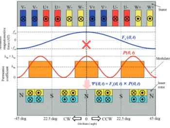
近年,欧州における自動車の二酸化炭素(CO2)排出規制 に対応するためにプラグインハイブリッド車(PHEV)の開 発が重視されている。欧州連合(EU)における燃費向上と 排ガスのクリーン化の推進において,2015 年の目標値はタ イヤなどによる燃費向上効果も含めて120 g/km(車両単体 では130 g/km)であるが,2021 年の目標値は 95 g/km と非 常に高い目標が設定されている(1)。2021 年の目標値を達成 するためにハイブリッド化や電気自動車の導入が必須とな るが,EU における乗用車排出ガス・燃費規制の ECE R101 rev. 3 規定では,充電する電力による CO2排出をゼロとして いるため,PHEV 化の効果が大きめに計算される(2)。そのた め,PHEV 化が特に欧州の自動車メーカーで積極的に推進さ れている。一方,PHEV 化に伴い,電動化による燃費改善効 果が大きいパワースプリット式HEV システムが重要となる が,従来の内燃機関に加えて電動コンポーネントが増加す るため,特にB セグメント以下のコンパクトカーにとって はコスト低減や,HEV パワートレインの重量低減が重要な 課題となる。 近年,パワースプリットHEV の小型化のために磁気変調 形磁気ギアモータを用いたHEV システムが提案されている (3)-(8)。従来の遊星歯車とモータを組み合わせたシステムに対 して二軸出力の磁気ギアモータを採用することで複合機能 化によりコンポーネント数を減らすことができ,小型・軽 量化・システム効率の向上が期待されている(3)。しかし,ス テータ側の回転磁界とロータの回転周波数が非同期で駆動 するため,永久磁石に対する外部磁場の変動が大きくなり, 高保磁力磁石を用いるとともに磁石渦電流損対策が必要に なる(8)。それらの課題に鑑み,筆者らは既に従来技術で損失 増加の主要因になっていた磁気ギアモータの非同期周波数 成分(非同期回転モード)に着目した磁石を用いない自励 式巻線界磁形磁気ギアモータを提案した(9)。提案モータは誘 導機の電磁誘導原理とダイオード整流形自己励磁技術を応 用することで磁石フリー化を実現している(10)。 本稿では,提案モータの可変速運転時における電機子電 流ベクトル制御の考察を行ったので報告する。(b) Modulated magnetic flux by modulator. 図3 磁気変調原理の説明図
Fig. 3. Modulated magnetomotive force distribution caused by modulator.
Number of rotor poles 16 Number of modulator poles 12
Stator outer diameter 120 mm Rotor diameter 61.2 mm Axial length of core 49.5 mm Air gap length 0.7 mm Maximum current 150 Arms
Armature winding resistance 15.1 mΩ / phase Number of armature coil-turn 8
Winding connection 4 series - 2 parallel Number of I-coil turn 10 Number of F-coil turn 11
I-coil resistance 79 mΩ / pole F-coil resistance 47 mΩ / pole Thickness of iron core steel plate 0.3 mm (30DH)
図2 ロータ巻線整流回路
Fig. 2. Rotor winding connection using full-bridge rectifier.
2. 差分周波数の変動磁束による自励原理
〈2・1〉 モータ構造 図 1 と表 1 にステータの基本波回 転磁界とロータ回転周波数の差分周波数で変動する磁束を 界磁エネルギー源とする自励式巻線界磁形磁気ギアモータ (ステータ極対数Ps = 4,インナーロータ極対数 Ppm = 8,変 調子極数Pm = 12)の径方向断面図と主要諸元を示す(11)。測 定環境の都合上,ステータコア外径がφ120 mm,積厚が 49.5 mm のダウンサイズした原理検証機を試作する予定である。 提案モータは,従来構造の磁気変調形磁気ギアモータと同 じでステータとアウターロータの変調子(Modulator),イン ナーロータのブラシレス巻線界磁ロータ(WF-rotor)で構成 される。従来の一般的な磁石形インナーロータ構造の場合 に問題となっていたロータに対する非同期周波数の磁束成 分による磁石渦電流損増加に対して,その磁束変動を界磁 エネルギー源として活用した磁石フリー磁気ギアモータの 構造としている点に特長を有する。図 2 に示すように突極 構造に2 種類の巻線(誘導起電力発生用の誘導コイル I-coil と界磁極形成用の界磁コイルF-coil)を巻き,それぞれの巻 線をダイオード整流回路で結線することにより,ロータに 鎖交する非同期の磁束成分(差分周波数磁束)で発生する 誘導起電力により自励する(12)。 〈2・2〉 差分周波数の磁束成分 図 3 に磁気変調形磁気 ギアモータの電機子巻線によって発生した電機子磁束が変 調子(Modulator)を介して,変調子とインナーロータの間 のギャップに発生する磁束分布を模擬的に表す。この図に 示すように,電機子起磁力 Fs(θ, t)が正弦波状に分布すると図4 HEV システムに磁気ギアモータを用いた共線図 Fig. 4. Collinear chart applied magnetic geared motor for HEV system. 仮定し,同図のような位相基準とすると,回転磁界の極対 数 Psと機械的な角速度ωsを用いて次式で表すことができ る。 Fs(θ,t)=faccos
{
Ps(θ−ωst)}
(1)}
ここで,facは起磁力の振幅である。 次 に 変 調 子 に 起 因 す る パ ー ミ ア ン ス 係 数 の 空 間 分 布 P(θ, t)についても正弦波状になると仮定すると,変調子の極 数 Pm,機械的な角速度ωmを用いて次式で表すことができ る。 (2){
( ) cos ) , ( t P t Pθ =λdc+λac mθ−ωm ここで,λdcはパーミアンス係数の直流分,λacは変動分を表 しており,0 ≦ P(θ, t) ≦ 1 である。したがって,変調後の ギャップに作られる起磁力分布Fg(θ, t)は(1)と(2)の積として 次式のように求まる。{
}
⎭ ⎬ ⎫ ⎩ ⎨ ⎧ + − + − + + ⎭ ⎬ ⎫ ⎩ ⎨ ⎧ − − − + − + − = × = ) )( ( cos 2 1 ) )( ( cos 2 1 ) ( cos ) , ( ) , ( ) , ( t P P P t P P P P P f t P P P t P P P P P f t P f t P t F t F m s m m s s m s s m ac ac m s m m s s m s s m ac ac s s dc ac s gω
ω
θ
λ
ω
ω
θ
λ
ω
θ
λ
θ
θ
θ
(a) Armature magnetomotive force and modulated magnetomotive force with respect to current phase.
(b) Current phase at maximum electromagnet torque. 図5 電機子起磁力と磁気変調後の起磁力の位相関係 Fig. 5. Armature magnetomotive force and modulated magnetomotive force with respect to current phase.
(3) (3)より,変調後の起磁力は固定子巻線により発生する回転 磁界の極対数Psと同じ次数の成分(ステータ基本波回転磁 界)の他に,Pm-PsとPm+Psの2 つの回転磁界から構成さ れていることがわかる。また,それらの機械的な角速度ωpm, ωpm'はそれぞれ下記となる。 m s m m s s m s pm PP P ω PP P ω ω − + − − = (4) m s m m s s m s pm
P
P
P
P
P
P
ω
ω
ω
+
+
+
=
' (5) したがって,インナーロータの極対数PpmをPm-Psとすれ ば,(4)よりインナーロータは角速度ωpmで同期回転し,一方 でPpmをPm+Psとすれば,(5)よりインナーロータは角速度 ωpm'で同期回転することがわかる。なお,実際の磁気変調形 磁気ギアモータではパーミアンスの分布が方形波状になる ため,高調波の影響によりPm-Ps成分の方がPm+Ps成分よ りも大きくなる。そのため,一般にインナーロータの極対 数はPpm=Pm-Psが選ばれる(12)。よって,電機子巻線による 回転磁界,インナーロータ,および変調子のそれぞれの角 速度ωs, ωpm, ωmの間には次の関係式が成立する。 Ppmωpm=−Psωs+Pmωm (6) 上式より,例えば電機子磁束による基本波回転磁界の角速 度ωsが一定であっても変調子の角速度ωmを変えることでイ ンナーロータの角速度ωpmは変化することがわかる。したが って,図4 に示すように共線図関係が成立する。 一方,(3)の右辺第一項に示されるように電機子基本波回 転磁界が変調子パーミアンス係数の直流成分に重畳してイ ンナーロータに非同期回転磁界として鎖交する。共線図か らわかるようにこの非同期回転磁界は電機子基本波回転磁 界とインナーロータの回転周波数差が大きい場合には変動 磁束成分による誘導起電力が大きくなり,回転周波数差が なく同期回転している場合はインナーロータの回転磁界成(b) Inverse salient pole model. (b) Current phase-torque characteristics. 図7 逆突極モデルの電流位相-トルク特性
Fig. 7. Current phase-torque characteristics of inverse salient pole model.
(a) Armature rotating magnetic field. (b) Modulated rotating magnetic field. 図9 図 8(a)の駆動条件時の電機子回転磁界と変調後の 回転磁界のベクトル関係
Fig. 9. Rotating magnetic field vectors of armature magnetic field and modulated magnetic field in driving mode of Fig. 8 (a).
(a) Armature rotating magnetic field. (b) Modulated rotating magnetic field. 図10 図 8(b)の駆動条件時の電機子回転磁界と変調後の 回転磁界のベクトル関係
Fig. 10. Rotating magnetic field vectors of armature magnetic field and modulated magnetic field in driving mode of Fig. 8 (b).
分となる。この回転周波数差がある場合,従来の磁石式磁 気ギアモータの場合には同期しないため,インナーロータ の永久磁石にとっては渦電流損を大幅に増加させる原因と なっていた(8)。しかし,提案するダイオード整流式巻線界磁 形磁気ギアモータはこの差分周波数の磁束成分により誘導 起電力を得て,ダイオード整流により自励式電磁石を形成 することで従来の磁気ギアモータと同様の動作原理で磁石 フリー駆動が可能となる。
3. 電流位相-トルク特性
〈3・1〉 磁気変調後の起磁力 図 5 に変調子を静止させ た状態で電機子電流の位相を進角させたときの電機子起磁 力と磁気変調後の起磁力の位相関係を示す。同図に示すよ うに変調前後で逆相関係になるが,以下に数式で説明する。 ) 4 cos( ) (θ = ac θ−δ s f F (7) ) 12 cos( ) (θ =λdc+λac θ−γ P (8) ) 16 cos( 2 1 ) 8 cos( 2 1 ) 4 cos( ) ( ) ( ) (δ
γ
θ
λ
δ
γ
θ
λ
δ
θ
λ
θ
θ
θ
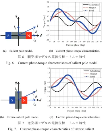
− − + + − + − = × = ac ac ac ac dc ac s g f f f P F F (9) (1),(2)において図 1 のポールコンビネーションで図 5 の時 間t = 0(位相基準)において電機子電流の位相をδ,変調子 の位相基準に対する位相ずれをγとおくと(7),(8)で表され る。(3)と同様に変調後の起磁力は(9)で求まる。(9)より,右 辺第一項の電機子磁束による基本波回転磁界と右辺第二項 のインナーロータが同期する回転磁界の位相関係が逆相に なっていることがわかる。すなわち,電機子電流位相を進 うに互いの回転磁界は逆方向に 回転する。これは電機子磁束による基本波回転磁界 4θが CCW 方向に回転する場合,変調後の回転磁界 8θ が CW 方 向に回転することを意味する。電流位相を進角させていく と,電機子磁束による基本波回転磁界がCCW 方向に回転す る場合(U⇒V⇒W の相順で通電),図 5(b)の電流位相 (δ = 90 deg)にて電磁石トルクが最大となることがわかる。 角させると図 5(a)に示すよ 〈3・2〉 電流位相-トルク特性 図 6 と図 7 に電機子磁 束による回転磁界が CCW 方向に回転している場合の順突 極モデルと逆突極モデルにおける電流位相-トルク特性を 示す。同図に示すように順突極モデル(Ld>Lq)の場合は最 大トルクが第一象限に存在し,逆突極モデル(Ld<Lq)の場(a) CW direction of armature rotating magnetic field.
(b) CCW direction of armature rotating magnetic field. 図11 電流位相-トルク特性 Fig. 11. Current phase-torque characteristics.
合は最大トルクが第二象限に存在する。図 1 に示すように 提案する磁石フリー磁気ギアモータは突極性を有する巻線 界磁形ロータのため,順突極モデルとなる。 ここで図8 に示す 2 つの動作モードで電機子磁束による 回転磁界と変調後の回転磁界のベクトル関係について説明 する。2 つの動作モード(Mode-1,Mode-2)について Mode-1 は図8(a)に示すように回転磁界が CW 方向(通電の相順が U ⇒W⇒V)でインナーロータが CCW 回転であり,Mode-2 は図8(b)に示すように回転磁界が CCW 方向(通電の相順が U⇒V⇒W)でインナーロータが CCW 回転である。図 9(a) に図8(a)の Mode-1 における電機子磁束ベクトルを示し,同 図(b)に変調後の磁束ベクトルを示す。図 10(a)に図 8(b)の Mode-2 における電機子磁束ベクトルを示し,同図(b)に変調 後の磁束ベクトルを示す。図 9 および図 10 より,Mode-1 の場合はインナーロータは順突極機と同じ電流位相-トル ク特性となることがわかる。一方,反作用トルクを受ける 変調子の電流位相-トルク特性は順突極機と逆相のトルク 特性となることがわかる。Mode-2 の場合はインナーロータ は順突極機の逆相のトルク特性となるため,変調子の電流 位相-トルク特性は順突極機と同じトルク特性となること がわかる。
(a) Modulator speed-modulator torque characteristics.
(b) Modulator speed-armature current phase characteristics.
(c) Modulator speed-differencial frequency characteristics. 図12 HEV モード最大トルク制御時の可変速トルク特性 Fig. 12. Adjustable speed drive characteristics under maximum torque control in HEV drive mode.
上記のベクトル関係を確認するために電磁界解析(汎用
ソフトのJMAG-Designer ver. 14 を使用)により提案モータ
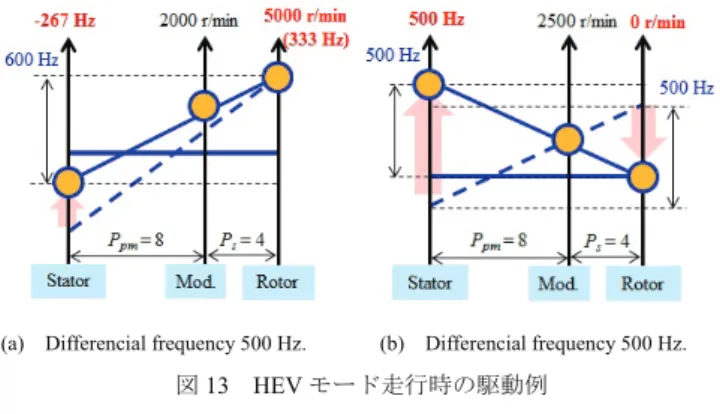
図13 HEV モード走行時の駆動例 Fig. 13. HEV drive mode.
(4) M. Fukuoka, K. Nakamura, H. Kato and O. Ichinokura: “A Consideration of the Optimum Configuration of Flux-Modulated Type Dual-Axis Motor”, IEEJ Technical Meeting, RM-13-141 (2013)
(5) N. Niguchi and K. Hirata: “A Novel Magnetic-Geared Motor”, Japan Society of Applied Electromagnetics and Machanics, Vol. 21, No. 2, pp. 110-115 (2013)
を図11 に示す。図 11(a)は図 8(a)の Mode-1 のときの電流位
相に対するトルク特性であり,同図(b)は図 8(b)の Mode-2 の ときの電流位相に対するトルク特性である。同図に示すよ うに電磁界解析の結果から図9 および図 10 と(9)で述べた電 機子磁束による回転磁界と変調後の回転磁界が逆相関係に なることを確認できる。さらに,提案モータは突極性(Ld >Lq)を有するため自励式電磁石トルクに加えてリラクタン ストルクも利用できることが確認できる。
(6) L. Jian and K. T. Chau: “Design and Analysis of Integrated Halbach-magnetic-geared Permanent-magnet Motor for Electric Vehicles”, Journal of Asian Electric Vehicles, Vol. 7, pp. 1213-1219 (2009)
(7) L. Jian and K. T. Chau: “Design and Analysis of a Magnetic-Geared Electric-Continuously Variable Transmission System Using Finite Element Method”, Progress In Electromagnetic Research, Vol. 7, pp. 47-61 (2010)
(8) T. Tonari, H. Kato and H. Matsui: “Study on Iron Loss of Flux Modulated Type Dual-Axis Motor”, IEEJ Technical Meeting, RM-13-142 (2013)
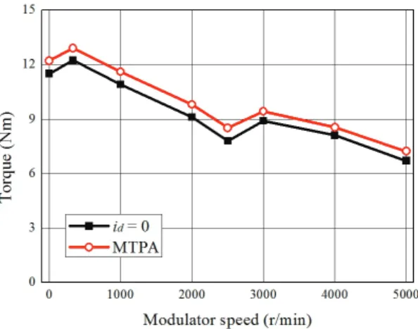
〈3・3〉HEV モード時の最大トルク制御 図 12(a)に HEV モード(インナーロータをエンジンに直結,変調子の出力 軸をドライブシャフトに接続)で最大トルク制御時の可変 速トルク特性を示す。なお,文献(13)のようにインナーロー タ(ダイオード整流形巻線界磁ロータ)に鎖交する電機子 回転磁界とロータ回転周波数の差分周波数で変動する磁束 成分が最大となるようにインナーロータの回転速度(エン ジンの回転速度)を制御することを想定している。同図(b) にそのときの電流位相の変化を示す。図11 に示すように提 案モータはリラクタンストルクを利用できるため,id = 0 制 御に対してMTPA 制御することでトルクの向上が可能であ る。一方で,図12(b)より変調子の回転速度が 2500 r/min に おいて電流位相が180 度シフトする。これは図 13 に示すよ うに差分周波数が小さくなる,すなわち同期回転モードに 近づいた駆動点を境に差分周波数が最大になるように電機 子回転磁界をCW から CCW に急激に変化させているためで ある。
(9) M. Aoyama, Y. Kubota and T. Noguchi: “Proposal of Rare-Earth-Free Brushless Wound-Field Magnetic Geared Motor for HEV Application”, IEEJ Annual Meeting, No. 5-037, pp.68-69 (2015)
(10) M. Aoyama and T. Noguchi: “Experimental Verification of Radial-Air-Gap-Type Permanent-Magnet-Free Synchronous Motor Utilizing Space Harmonics with Auxiliary Poles”, IEEJ Trans. IA, Vol. 135, No. 8, pp.869-881 (2015)
(11) M. Aoyama, Y. Kubota, T. Noguchi and Y. Motohashi: “Prototype Design of Permanent-Magnet-Free Magnetic Geared Motor”, IEEJ Industry Applications Society Conference, No. 3-8 (2015) (12) M. Aoyama, Y. Kubota, T. Noguchi and Y. Motohashi: “Study on
Rotor Rectifier Circuit of Permanent-Magnet-Free Magnetic Geared Motor for HEV Application”, IEEJ Technical Meeting, MD-15-076, RM-15-057, VT-15-004 (2015)
(13) M. Aoyama, Y. Kubota, T. Noguchi and Y. Motohashi: “Adjustable Speed Drive Performance of Permanent-Magnet-Free Magnetic Geared Motor under HEV Drive Mode”, IEEJ Industry Applications Society Conference, No. 3-9 (2015)