JAIST Repository
https://dspace.jaist.ac.jp/
Title A Study of Timing Issues for Multimodal Human Machine Interface for Smart Home
Author(s) 呉, 楚瑶
Citation
Issue Date 2018-09
Type Thesis or Dissertation Text version author
URL http://hdl.handle.net/10119/15468 Rights
A Study of Timing Issues for Multimodal Human
Machine Interface for Smart Home
By WU Chuyao
A thesis submitted to
School of Information Science,
Japan Advanced Institute of Science and Technology,
in partial fulfillment of the requirements
for the degree of
Master of Information Science
Graduate Program in Information Science
Written under the direction of
Professor Yasuo Tan
A Study of Timing Issues for Multimodal Human
Machine Interface for Smart Home
By WU Chuyao (1510206)
A thesis submitted to
School of Information Science,
Japan Advanced Institute of Science and Technology,
in partial fulfillment of the requirements
for the degree of
Master of Information Science
Graduate Program in Information Science
Written under the direction of
Professor Yasuo Tan
and approved by
Professor Yasuo Tan
Associate Professor Yuto Lim
Research Associate Professor Razvan Florin Beuran
August, 2018 (Submitted)
Abstract
Nowadays, vary with the development of Wireless Networks, rapid evolution of Internet of Things (IoT), smart home, smart city are very near to us. Smart Home is a home like environment that possesses ambient intelligence and automatic control, in which to responds to behavior of residents with various facilities. The main target of smart home is to support resident goals of life comfort, safety, security, energy-efficiency and enhance intelligent living. One important thing towards making a smart home is automation. The automation could be related to the individual appliances or equipment being intelligent enough to take local decisions. Traditional human machine interface (HMI) is good enough for the normal user, but not adaptive to ambient environment. Thus, multimodal HMI is proposed which process two or more combined user input models, such as original switch, remote controller, speech, pen, touch, manual gestures, gaze, and head and body movements in a coordinated manner with system output of home appliance. These kind of combinations always lead conflict problems, thus, the timing issues need to be analyzed before the implementation of MHMI.
In this research, I do a study of timing issues for multimodal human machine interface for smart home. In the first chapter, I introduced the background of MHMI for smart home environment, which is the trend of near future to any human in the world. The aim of this research is that before create the novel MHMI for smart home, the timing issues need to be discussed. Thus, the survey of home appliance and related interaction methods is necessary. Then, based on the survey, the real experiment of MHMI should be built to measure the real date for the analysis. Moreover, based on the results, the questionnaire survey with absolute category rating to evaluate the tolerable response time is important. The results of tolerable response time can be used for the optimization of MHMI.
Chapter 2 presents the introduction about smart home. By defining smart home, dis-cussing the components of smart home. Then, a comprehensive judgment of my research background in human machine interface for smart home is introduced. In addition, the
traditional human machine interface has lots of limitations so we need to explain how to build a multimodal human machine interface to help user interact with machine in Smart Home.
Chapter 3 discusses the typical classification about the existing User Interface and proposes the basic four categories for MHMI. After the explanation of four user interfaces, the time issues of MHMI is described with the combination of these UI.
In Chapter 4, a real experiment environment is setup to do the response time mea-surements of TUI, AUI, MUI and GUI. Based on the typical response time of each UI, a additional delay range is designed to test the human feeling/tolerable timing of each UI. A questionnaires with absolute category rating is prepared for the tolerable experiments. Based on the results, the time issues of MHMI is discussed for smart home. Instead of real implementation of console, AUI and TUI are used to evaluate the importance and effec-tiveness of synchronization for MHMI. Instead of real implementation of console, AUI and TUI are used to evaluate the importance and effectiveness of synchronization for MHMI. At last, we discussed the contribution of these research work, and show the future works.
Acknowledgements
First and foremost, I am greatly thankful to my main supervisor, Professor Yasuo Tan for his valuable guidance and encouragement to me throughout this research work. The door to Professor Tan office was always open whenever I ran into a trouble spot or had a question about my research. Without his illuminating instruction and motivation on the direction of the research, this research could not have been completed.
Second, I would like to affirm my profound respect and gratitude to my second super-visor, Associate Professor Yuto Lim as well. He offer me numerous great advise and always inspired me in my research. He taught me how to resolve problems in the research with his knowledge and patience.
I also would like to extend my thanks to Research Associate Professor Razvan Florin Beuran for his precious time in attending my mid-term defence, final defence and review-ing my thesis. I am deeply indebted to his for his very valuable suggestion and comments on this thesis.
Besides, I would like to extend heartfelt gratitude to Professor Ryo Maezono for his helping in my minor research. He told me how to study in a brand new field and high-efficiency work.
In addition, I also sincerely thanks to Assistant Professor Saher, Dr. Marios, Mr. Makio, Dr. YU and everyone else in Tan&Lim lab for their advice, suggestions and knowledge sharing that helped me in the completion of this study.
Last but not least, I must express my very profound gratitude to my family’s members especially my lovely parents for providing me with unfailing support and invariably en-couragement throughout my years of study in a foreign country and through the process
of research and writing this thesis. I also would like to extend my thanks to one and all whom, have lent their help in this research.
Contents
1 Introduction 1
1.1 Research Background . . . 1
1.2 Research Aim . . . 2
1.3 Research Objectives and Methods . . . 3
1.4 Research Significance . . . 4
1.5 Organization of this Thesis . . . 4
2 Smart Home and Multimodal Human Machine Interface 6 2.1 Introduction . . . 6
2.2 Background of smart home . . . 9
2.3 Components of Smart Home . . . 10
2.4 Systems in Smart Home . . . 12
2.5 Human Machine Interface (HMI) . . . 14
2.6 Multimodal Human Machine Interface (MHMI) . . . 16
2.7 Summary . . . 19
3 Multimodal Human Machine Interfaces Classification and Timing Is-sues 20 3.1 Introduction . . . 20
3.2 Background . . . 21
3.3 Classification of HMI for smart home . . . 24
3.3.2 Acoustic User Interface (AUI) . . . 25
3.3.3 Motion User Interface (MUI) . . . 26
3.3.4 Graphical User Interface (GUI) . . . 27
3.4 Timing Issues of MHMI for Smart Home . . . 28
3.5 Discussions . . . 30
3.6 Summary . . . 31
4 Timing Issues on each User Interface 32 4.1 Introduction . . . 32
4.2 Experiment Setting . . . 33
4.2.1 Experiment Environment . . . 34
4.2.2 Experiment Devices . . . 36
4.3 Measurements of typical response time . . . 36
4.3.1 TUI Settings . . . 37
4.3.2 AUI Settings . . . 38
4.3.3 MUI Settings . . . 40
4.3.4 GUI Settings . . . 42
4.3.5 Results of Necessary RT . . . 43
4.4 Classification of ACR Levels . . . 45
4.5 Experimental Design . . . 46
4.6 Numerical Results . . . 47
4.6.1 Pie and Boxplot Results of TUI . . . 47
4.6.2 Pie and Boxplot Results of AUI . . . 49
4.6.3 Pie and Boxplot Results of MUI . . . 50
4.6.4 Pie and Boxplot Results of GUI . . . 52
4.6.5 Discussion . . . 53
4.7 Evaluation of Synchronization with TUI and AUI . . . 55
4.7.1 Experiment Design . . . 55
4.7.2 Numerical Results . . . 56
5 Conclusions and Recommendations 59
5.1 Concluding Remarks . . . 59
5.2 Future Works . . . 60
A GPIO pins of Raspberry Pi 61 B Typical Response Time of each User Interface (ms) 62 C Code of Experiment 66 C.1 TUI . . . 66
C.2 AUI . . . 69
C.3 MUI . . . 69
List of Figures
2.1 Typical Smart Home Appliances . . . 7
2.2 Typical Components of Smart Home . . . 11
2.3 Ventialation, Shading, Heating and Air Conditioning System . . . 13
2.4 Human Machine Interface . . . 15
2.5 Multimodal Human Machine Interface . . . 16
3.1 Types of Human Machine Interface . . . 21
3.2 Typical TUI - Button Switch . . . 24
3.3 Typical AUI - Amazon Echo Plus . . . 25
3.4 Typical MUI - Kymera Magic Wand Remote Control . . . 27
3.5 Typical GUI - Display Screen Smart Phone . . . 28
3.6 UML Sequence Diagram on Synchronization Problem of MHMI . . . 29
3.7 UML Sequence Diagram on Synchronization Problem Solution of MHMI . 30 4.1 Measurement Methodology of Typical Response Time for each UI . . . 33
4.2 Experiment Environment . . . 34
4.3 Image of Raspberry Pi and its Block Diagram . . . 35
4.4 Other Device for Experiment . . . 35
4.5 Experiment Setting of TUI . . . 37
4.6 Experiment Setting of AUI . . . 39
4.7 Operation setting on Node-RED . . . 40
4.8 Experiment Setting of MUI . . . 41
4.10 24 Hours Experiments of Necessary Response Time Measurements . . . 44
4.11 Experiment Design for ACR Evaluation . . . 46
4.12 Results of ACR levels on TUI . . . 48
4.13 Results of ACR levels on AUI . . . 50
4.14 Results of ACR levels on MUI . . . 51
4.15 Results of ACR levels on GUI . . . 53
4.16 Percentage of ACR Levels on Each UI . . . 54
List of Tables
4.1 Experiment Devices used for Measurements and Evaluation . . . 36
4.2 Experiment Parameters for ACR Evaluation . . . 47
List of Abbreviations
ACR Absolute Category Rating
AI Artificial Intelligence
AUI Acoustic User Interface
AWS Amazon Web Services
BCI Brain Computer Interface
CHI Computer Human Interaction
CPU Central Processing Unit
ECG Electrocardiogram
EETCC Energy Efficient Thermal Comfort Control
EKG Electrocardiogram
EMG Myoelectric Interaction
EOG Electrooculography
GUI Graphical User Interface
GPIO General-Purpose Input/Output
GPU Graphics Processing Unit
HCC Human Computer Communication
HMI Human Machine Interface
HD High Definition
IoT Internet of Things
IR InFrared
LAN Local Area Network
MAN Metropolitan Area Network
MHMI Mulitmodal Human Machine Interfaces
MMI Man Machine Interface
MUI Motion User Interface
OI Operator Interface
PAN Personal Area Network
QoE Quality of Experience
RF Radio Frequency
RT Response Time
SoC System on a Chip
TUI Tactile User Interface
UI User Interface
USE Users Using Questionnaires
USI User System Interface
Chapter 1
Introduction
In this chapter, the background, aim, objectives of this research are introduced. The organization of this thesis is described at the end of this chapter.
1.1
Research Background
In recent years, with the rapid development of consumer electronics and the Internet of Things, the smart home has become a hot spot for research activity. The smart home technical base consists of a large variety of sensors, actuators and computational nodes that work together in harmony to provide adequate assistance and improve the quality of life of the occupants of a house. The base to support these sensors, actuators, and computational nodes is the network. Normally, the networks can be classified by their scale, i.e., personal area network (PAN), local area network (LAN), metropolitan area network (MAN), wide area network (WAN), etc. Basically, LAN is mostly used for the smart home environment. Also, there are lots of network protocols which are important for the smart home environment, e.g., TCP/IP, ECHONET, IEEE 802.11 groups (WiFi), Bluetooth, ZigBee, etc. The more detail of above information is introduced in Chapter 2. Besides, interaction between human and home device (e.g., air-condition, TV, light, camera/monitor, etc.) takes an paramount importance in the smart home Environment. Although there are a lot of effort in Human Computer Interfaces (HCI) has been invested
by the research community, this is the first time where timing issues of multimodal human machine interfaces have been deeply discussed before broadly deployed in the smart home. These multimodal interfaces have the potential to improve the interaction of the user with the home substantially, by providing the most appropriate to the user and/or combining various modalities to improve usability.
Multimodal interfaces are comprised by various components each providing a unique modality. The orchestration and synchronization of these components is necessary to provide useful multimodal human machine interfaces. Due to the heterogeneous nature of the various components and their connectivity options, time issues (e.g., synchronization) become a challenging task. The key to solving this problem is a mechanism that simplifies time issues to avoid synchronization problems while at the same time keeping delay to a bare minimum. Currently, to the best of my knowledge such a general synchronization mechanism does not exist.
1.2
Research Aim
Technological advances in consumer technology and network connectivity enable the cre-ation of Mulitmodal Human Machine Interfaces (MHMI) in the context of the smart home. Compared to user interfaces that utilize single modality, these multimodal interfaces have the potential to be more user-friendly, customizable and intuitive in their use. However, failing to orchestrate the various components of a MHMI may lead to suboptimal user experience and thus reduce the users satisfaction regarding the smart home. This re-search proposes a synchronization mechanism for MHMI in the smart home that aims to reduce synchronization lag and simplify the orchestration of the various components of an MHMI. For evaluation purposes, various MHMIs will be implemented and compared to traditional single modality interfaces. The MHMIs will be evaluated by users using questionnaires such as USE [1].
1.3
Research Objectives and Methods
The objectives of this research are list as follows:
• Survey of home appliances and related interaction methods
– Conduct a preliminary survey regarding the currently available smart home appliances and classify the interaction methods that they provide, similar to [2]. Along with [3], the results of the survey will help in better understanding interface modalities and provide inspiration for the experiments that will be conducted in this research.
– To produce original classification of HMI for smart home, so that it can simplify the orchestration of the various components of MHMI.
• Experiments setup for measurement
– For this objective, users will be asked to complete various commonly occurring tasks, such as turn on/off the lights, set the temperature of the air condition, operate the TV and others, with each kind of HMI. Each task will be attempted first by using a single modality HMI and then discussing the time issues. During the experiments various statistical data (such as task completion time) will be collected. Upon the completion of an experiment the user will be asked to fill in the questionnaires selected in next stage.
• To analyze Quality of Experience (QoE) with Absolute Category Rating (ACR) levels in order to clarify the allowable range of delay for each user interface (UI) of MHMI
– Conduct preliminary research regarding questionnaire-based evaluation. ACR is a test method used in quality tests. In this step, preexisting questionnaires such as USE will be considered for evaluation purposes. However, should these questionnaires prove to be insufficient for our purposes, the design of a new questionnaire that covers the modalities that were discovered of first objective
shall be pursued. Different factors such as user satisfaction, task completion time will be considered. Previous evaluation work can be found in [4, 5, 6].
– Define ACR levels that depend on ITU-T P.910 to define 5 levels which include Excellent, Good, Fair, Poor and Bad.
• Discuss synchronization model for multimodal HMI
– Discuss the key synchronization mechanism responsible for orchestrating the various components of an MHMI. This mechanism should be designed to re-spond to application state change events, coordinate the logical input model provided by the MHMI as well as distribute updates to every connected compo-nent of the MHMI with minimal time delay which is results from the evaluation.
1.4
Research Significance
The significance of this research could be split in three parts:
• First, as a result of this research a general discussion on time issues will be developed that supports the creation of heterogeneous MHMIs. Using the results of time issues, the task of composing MHMIs from components will be vastly simplified.
• Secondly, the viability of MHMIs that use the above results will be evaluated. Us-ability and ease of use of MHMIs will be evaluated using standard questionnaires such as USE.
• Finally, this research has the potential to benefit society as a whole by making smart home technologies more accessible to the masses and simplifying everyday tasks for people who are in need of support and assist in their daily lives.
1.5
Organization of this Thesis
• Chapter 2
Presents the introduction about smart home. By defining smart home, discussing the components of smart home. Then, a comprehensive judgment of my research background in human machine interface for smart home is introduced. In addition, the traditional human machine interface has lots of limitations so we need to explain how to build a multimodal human machine interface to help user interact with machine in Smart Home.
• Chapter 3
Discusses the typical classification about the existing User Interface and proposes the basic four categories for multimodal HMI. After the explanation of four user interfaces, the time issues of multimodal HMI is described with the combination of these UI.
• Chapter 4
A real experiment environment is setup to do the response time measurements of classified four UI. Based on the typical response time of each UI, a delay range is designed to test the human feeling/tolerable of each UI. A questionnaires with absolute category rating is prepared for the evaluation. Based on the results, the time issues of multimodal HMI is discussed for smart home.
• Chapter 5
Summarizes the work in this research, draws contributions and mentions the future work.
Chapter 2
Smart Home and Multimodal
Human Machine Interface
In this chapter, I present the necessary background of smart home and other informa-tion of the multimodal human machine interface. The first secinforma-tion introduced the basic information of smart home. The second section is about the background of smart home, including the definition of smart home, and so on. The third section introduces the key components of smart home, such as smart devices, network protocols, and human ma-chine interface. Based on these techniques, multimodal human mama-chine interfaces is the inevitable trend of development.
2.1
Introduction
Smart Home is a home like environment that possesses ambient intelligence and automatic control, in which to responds to behavior of residents with various facilities [7]. The main target of smart home is to support resident goals of life comfort, safety, security, energy-efficiency and enhance intelligent living. The concept of smart home has been introduced more than a decades. Now, the smart home is include several components, such as the networking, all of the smart devices and equipment or Internet of Things (IoT) devices and equipment [8], the control system/platform, the interface between machine and human,
!"#$%$&&'
()*+$&'
,*-$#*'
.//#'0/12'
3$*4'5',//%'
6*#*7$'
(-/2$'+$4$14/#'
(-*#4'8)/9$'
0"7)4"97'
:;'
<=&"1'
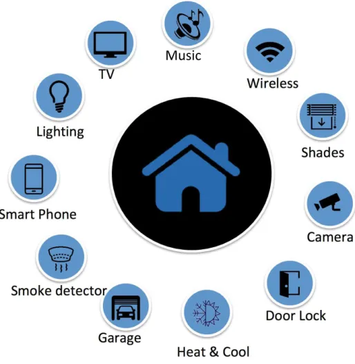
Figure 2.1: Typical Smart Home Appliances
etc.
As we know, the internet can provides access to different kinds of information even with a simple action, such as push of a button. The whole network is move to a novel paradigm, which is called IoT. IoT is defined as the network of physical devices, vehicles, home appliances, and other items embedded with electronics, software, sensors, actuators, and connectivity which enables these things to connect and exchange date [9], creating op-portunities for more direct integration of the physical world into computer-based systems, resulting in efficiency improvements, economic benefits, and reduced human exertions [10]. Thus, it makes the control of home appliance more easier, convenience and efficiency.
In Figure 2.1, the typical home appliances are shown. Almost all aspect of life in which technology is introduced (light bulbs, washers, water boiler, etc.) are proving alternative
technologies for smart homes:
• Smart TV connects to the Internet to access/download through applications, such as video and music. For the smart TVs, by control with voice or gesture recognition is more “smart” than traditional remote controller.
• For smart light systems, rather than the original switch or “IR” based remote con-troller, use smart phone Apps or with the sensor detection to remotely and cus-tomized adjust the lighting, not only on/off, also include intensity and color adjust-ment with smart light bulbs.
• For smart thermostats, e.g., energy efficient thermal comfort control (EETCC) sys-tem [11], come with integrated ECHONET [12], to reduce energy consumption while satisfying the thermal comfort level of residents in timely manner by using air-conditioner, window, and curtain. The benefits of EETCC system is that it use the natural resources for thermal comfort by opening window and/or curtain.
• For smart home door/gates, smart locks and garage-door openers, resident users can allow or deny access to visitors. Smart locks can also detect that residents’ location, if they are near and then the doors can unlock automatically.
• For smart home security, web cameras are necessary. Home situation can be re-motely monitored when resident are away of home or on their vacation. Based on the technology of image identification and artificial intelligence (AI), residents, vis-itors, pets and burglars can be easily identified, if suspicious behavior is detected, resident also can received notify authorities.
• For smart kitchen system, all kinds of kitchen appliances can be controlled auto-matically. E.g., smart coffee makers can brew you a fresh cup after you woke up; smart refrigerators can records the expiration dates and track them, you can get notifications if some of them are expired; also, if some of your favorite food is not enough, like eggs, it can automatic shopping on the internet, or based on what’s
inside, it can provide resident food menu on how to cooking them. Similar for the washing machines and dryers.
• For household system, monitors are sense electric and water situations. If there is some failures or accidents, they can automatic turn off the electric or water for resident safety live.
2.2
Background of smart home
A smart home, then, may be defined as a residence or a building with equipment which can be remotely controlled and operated from any location in the world by means of smart devices, such as through a smart phone. Smart home comprises of devices that provide comfort, security, convenience, energy-efficiency and enhance intelligent living. The devices communicate and interact with each other and form a connected network system. Smart home is usually understood as automated home but the actual capabilities are beyond of automation. Smart home comprises of a set of connected gadgets with intelligence that help them in executing the task and take necessary decisions.
Smart Homes present some very exciting opportunities to change the way we live and work, and to reduce energy consumption at the same time. The owners of smart homes are empowered with conveniences like: being able to check messages, open windows, operate lights and curtains and monitor how much money the house has made or saved from the renewable energy system or smart energy management system, through their respective smart phones, from anywhere in the world.
One important thing towards making a smart home is automation. The automation could be related to the individual appliances or equipment being intelligent enough to take local decisions. A simple example could be a standalone porch light that turns on/off only when there is movement detected or wirelessly operated when curtains or blinds are turn down/up. Another example could be a camera that records the movements for a period of time after a gate is opened.
various sensors and automating elements inside it. In fact it may be commented here that many other functions of connectivity may be considered as embedded within a Smart Home. As an example, remote patient monitoring, vehicle charging, solar rooftops, me-tering, home appliances, electric and air conditioning controls, entertainment, health and fitness equipment and a host of other connected devices are part of a home and a smart home system is expected to provide a unified view of all these services.
2.3
Components of Smart Home
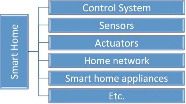
For smart home, the components must be employed includes the following elements: intelligent control, home automation and internal network [13]. The intelligent control is provided by a control system, comprised of two types of elements, i.e., sensors and control agent. Sensors is used to monitor, report the status of the home situation and control the home appliance [14]. Control agent normally acts on the information which are provided by the sensors. Home automation functions are performed by electrical or electronic equipment; which are called actuators. Actuators interact and modify the environment by performing specialized tasks. These tasks are typically applied to more complex goals defined by the system user. The purpose of the home network is simply to ensure that all components can send and receive instructions to each other. More detail is introduced as follows (see Figure. 2.2):
• Control System is a critical part of smart home due to it determines reliability, usability and overall effectiveness of the solution provided. This system is written as a piece of software that is run on a computer or embedded in an electronic de-vice. This system offer the ability to control a subset of the home appliances from a specified location. The basic idea of home automation is to employ sensors and control systems to monitor a dwelling, and accordingly adjust the various mecha-nisms that provide ventilation, heating and cooling, lighting, automated Appliances and Furniture, security and so on. These usecases are described in the following subsection.
!
"
#$
%
&
'(
"
)
&
*(+%$(,&!-.%)"&
!)+.($.&
/0%1#%($.&
'(")&+)%2($3&
!"#$%
&
4(")7,6#+0).&
7%08&
Figure 2.2: Typical Components of Smart Home
• Sensors are used to measure all of the data that can be used for the “smart” home, such as temperature sensors, wind sensors, etc. They sense all the information generated inside/outside the house. Based on the information, the control system can provide more intelligent actions for different type of life styles. The real-time measuring and monitoring of home appliances/environments is a key and integral part of smart home.
• Actuators are electrical or electronic devices taht can control a household appliance. When it is individual device, it need to be electrically coupled with the appliance and can be controlled when some simple commands is executing, such as switch-ing on/off. When it is embedded within the appliance itself, they can be more sophisticated and provide more value added to the resident user.
• Home network can be subdivided into two main areas, depending on the communi-cation media used:
– Wired network is a system which plug in directly to the house electrical network (electrical mains) and do not require additional cabling, such as TV cable,
Wireless LAN cable, etc. This technology can be simply configured with low cost. It’s weakness may be the lack scalability and considered the least reliable due to its susceptibility to electrical interference.
– Wireless network is a system which do not require any wires to operate. This technology can be further subdivided into Radio Frequency (RF), and Infrared (IR). They are commonly used due to the low cost per unit. The typical techniques are such as WiFi, ZigBee, Bluetooth, etc.
• Smart home appliances are already introduced in the previous section (see Figure 2.1). They are the core part of the components for smart home. They can provide comfort, entertainment, convenience, and efficiency to residents.
Although the way to use them “smartly” is important, the way to control them is also very important. Any software or devices that allows human to interact with a machine are collectively called Human Machine Interface (HMI) [15], which have great relationship with all above components.
2.4
Systems in Smart Home
Moreover, there are several typical systems in smart home. The detail are list as follows:
• Ventilation, Shading, heating and cooling Conditioning System
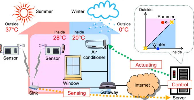
A proper heating, ventilation, and cooling system is a key parts of every smart home. This system works much more than programmable thermostats and timer controls [16]. Smart home technologies on ventilation, shading, heating and cooling system is important to give residents no matter where you are on the earth (see Figure. 2.3). Resident can feel confortable and also cutting down their energy bills by using an automated system monitoring or programs which lead to keep the home well-insulated or ventilated, such as EETCC system [11].
Moreover, you can free from small tasks, e.g., adjusting the insulation at home with these system. This might save your time and the energy as you have remote access
Summer! Winter! Inside
28
°
C
!
Inside20
°
C
!
Outside37
°
C
!
Outside0
°
C
!
Sensor! Sensor! Window! Air conditioner! Server! Gateway! Sink! Internet! Inside Outside Winter! Summer! Sensing! Actuating! Control!Figure 2.3: Ventialation, Shading, Heating and Air Conditioning System
outside your home, even as automatically control by itself depending on the changes on temperature of the current outside weather (see Figure. 2.3).
• Lighting System
With a single click on a button, or a flip on a switch, it is already possible to turn on/off all the lights in any house. In smart home, the lighting system should automatically control all of the lights, not only turn on/off, also brighten or set a dim level in a selected room depending on resident user’s situation. Other than having remote access to all the lights, it also should allow resident users to program desired brightness in every room of their home.
• Appliances and Furniture Automation System
Smart home systems can offer voice-controlled appliances such as voice-controlled fun, TV, entertainment systems, AI voice system, and so on. Having these auto-mated home appliances relieves you away the laborious tasks especially it is nec-essary for the elders, children and disable people. Voice recognition based soft-ware/products are made them available for smart home environment, such as easily
program with simple commands to home appliances and so on.
• Home Security System
Home security system is the top component for every smart home. Smart home requires full security since it is vital to keep residents and their property safe from harm. As violence increases, home security systems are important to every home resident. Having a home security system installed contain many concepts, such as installation of wired surveillance cameras, smoke detectors, motion sensors, finger-print or eye scanners, and others. With installation of these concepts, the home can be definitely prevented burglary from occurring.
For this research, more focus are on the human machine interface rather than any other components. With the internet of things (IoT) became a dominant trend in the world,in order to operate the devices, HMI are becoming more complex. This research can simplify each HMI, and focus on the time issue for their combination in smart home. The light system is selected to do the evaluation of each type of human machine interface due to it is easy to implemented with low cost.
2.5
Human Machine Interface (HMI)
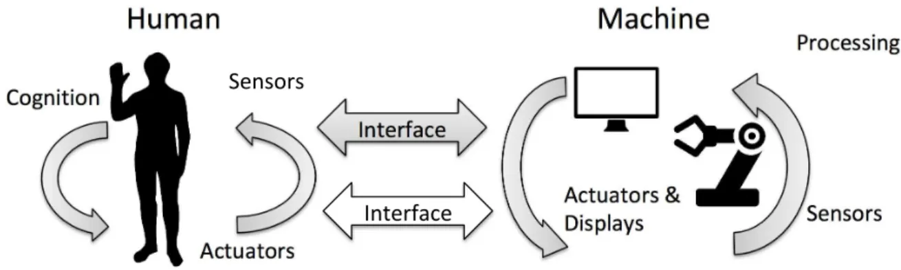
Human machine interface (HMI) is a component of certain devices that are capable of handling human machine interactions. The HMI consists both hardware and software that allow the translation of user inputs as signals for machines that, in turn, provide the required result back to the user. HMI technology has been used in many different industries, e.g., electronics, entertainment, medical, military, etc. HMI help in integrating humans into complex technological systems (for example, see Figure. 2.4). Human ma-chine interface is also called Computer Human Interaction (CHI), Man Mama-chine Interface (MMI), Human Computer Interaction (HCI), User Interface (UI), User System Interface (USI), Human Computer Communication (HCC) or Operator Interface (OI).
Vary with the development of IoT and wireless technologies, the HMI is not only for the industries, it is used anywhere, anytime in the world. In this research, the HMI is more
!"#$%&
'()"$)*+,& -*.%/)/*%&&0$(1/%2&
'()"$)*+,&3& 4/,56$7,& 82%,*+,& 9+*(2,,/%.& :%)2+;$(2& :%)2+;$(2& 82%,*+,&&Figure 2.4: Human Machine Interface
focus on the smart home. In HMI, the interactions basically contain two types, in another word, both human to machine and machine to human. In home environment, resident usually interact with home appliance through an interface. Thus, in this research it can be assumed that HMI stands for human machine interaction as well as human machine interface, and call HMI as User Interface (UI) for simple. Since HMI technology is ubiq-uitous, information can be exchanged between human and machine through sight, sound, feeling and other physical modes or cognitive modes. Typical HMIs include switch button, remote controller, motion detection sensors, touch screen and other peripheral devices, speech-recognition devices and any other interaction devices in home environment.
In smart home, the basis design of HMI largely depends on the understanding of resi-dents’ physical, behavioral and mental capabilities. Or we can say, ergonomics constitutes are the basic principles of HMI. In order to enhance the experience and efficiency for res-ident/user, HMI also bring unique opportunities to home applications, recreation and learning, e.g., [17, 18]. In fact, HMI helps resident to master the way of using equip-ment rapidly. A good HMI can bring realistic and natural interactions between user and external home appliance/devices.
Typically, HMI provides the advantages include error detection and reduction, system and user efficiency enhancement, reliability and maintainability improvement, increased user acceptance and comfort, reduction in training and skill requirements, reduction in physical or mental stress, reduction in task saturation, increased economy of production and productivity, etc [19, 20]. HMI technology is also widely used in other field, such
as displays on virtual and flat, pattern recognition, Internet access, personal computer interaction, data/program input for electronic devices, and information fusion. In smart home, the main goal of design HMI is easy interaction, low risk of injury, fatigue, error and discomfort, as well as improve the productivity and quality of interaction. Also, how to built the HMI to lead resident towards more natural interfaces that is more intuitive to use, and not carry out any restrictions on natural movements is getting more important.
2.6
Multimodal Human Machine Interface (MHMI)
Usually the traditional human machine interface in smart home is designed for the normal user, not adaptive to ambient environment. HMI like based on only one modality, can not provide a natural way of human interaction.
!"#$%$&'(
)'*"'*$&'( +**"'*$&'( ,-&*$&'((
+#*$&'(
."/#"0*$&'( )'*"/0/"*1*$&'(
20""#3( 4"%*5/"( 61#$17("809( :/$*$';( <( <( =10*$#(>"?$#"%( @1A7"*( B$>"&(#1-"/1( C$#/&03&'"( <( 61#$17("809( +5>$&(#5"%( B$%517(#5"%( @"8*D*&D20""#3( <( 2$;3*( ="1/$';( @&5#3(
+#*$&'(
."/#"0*$&'(
)'*"/0/"*1*$&'(
65%$&'( 6$%%$&'(E&-05*1*$&'(
>1*1(7"?"7( F"1*5/"(7"?"7( >"#$%$&'(7"?"7( <(Figure 2.5: Multimodal Human Machine Interface
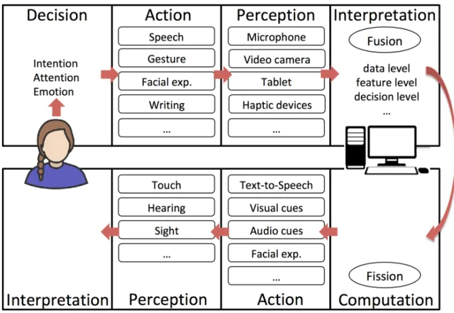
Thus, the multimodal HMI is proposed. For example, Figure. 2.5 is shown the mul-timodal human computer interface. Similar to mulmul-timodal human computer interface,
MHMI has same concept. When we imagine communication human-human, human re-ceivers information from many sources and not just using speech. For example, mimic, gesticulation and many others. Multimodal systems process two or more combined user input models, such as original switch, remote controller, speech, pen, touch, manual ges-tures, gaze, and head and body movements in a coordinated manner with system output of home appliance, similar as Figure. 2.5. This exchange of information is more natural than just using of one modality. This class of systems represents a new direction for computing, and a paradigm shift away from conventional human machine interfaces [21]. The growing interest in multimodal HMI design is inspired largely by the goal of sup-porting more transparent, flexible, efficient, and powerfully expressive means of human machine interaction. Multimodal HMI are expected to be easier to learn and use, and are preferred by users for many home appliance [22]. The future potential is significant when the system is considered for people with disabilities, elders, children, etc.
The advent of multimodal interfaces based on recognition of human speech, gaze, ges-ture, and other natural behavior represents only the beginning of a progression toward computational interfaces capable of relatively human-like sensory perception. Such inter-faces eventually will interpret continuous input from a large number of different visual, auditory, and tactile input modes, which will be recognized as users engage in everyday activities. The same system will track and incorporate information from multiple sensors on the users interface and surrounding physical environment in order to support intelligent adaptation to the user, task and usage environment.
General requirements of MHMI are list as follows:
• Supplementary and complementary use of different modalities
• Seamless synchronization of modalities
• Multilingual support
• Easy to implement
• Security and privacy
• Delivery and context
• Navigation specification
Multimodal HMI brings several advantages:
• Input overloading
In the case of using only one modality, every command transmitted only through this modality and it can lead to the “overloading” [23]. For MHMI, these overloading normally not exist.
• Flexibility
Since individual input modalities are well suited in some situations, and less ideal or even inappropriate in others, modality choice is an important design issue in a multimodal system. As systems become more complex and multifunctional, a single modality simply does not permit all users to interact effectively across all tasks and environments.
• Collection of information
Another major advantage of MHMI is a collection of information. This advantage can be easily explained using the example of the authentication/security system. Imagine a home security system using biometric features. In the case of using only one biometric feature such as speech (speaker recognition) which we know that the percentage is more than 80%, we would have to rely on it. This can in many cases, lead to a false identification. This disadvantage can be removed by an additional modality, such as the identification by the face [24].
• Redundancy
This advantage is similar to the collection of information from previous examples. Advantage can be explained on the same authentication system. Provided that the system is used to identify the speaker in an environment. Provided that the system
is used to identify the speaker in an environment, where success rate around 95% can be achieved under ideal circumstances. But in the real environment conditions, the environment can be adversely affected by various factors, such as noise. In this case, use redundant information from a system of identification using face.
• Minimizing cognitive load
As task complexity increases, there is evidence that users self manage their working memory limits by distributing information across multiple modalities, which in turn enhances their task performance during both perception and production [].
2.7
Summary
I would like to conclude this chapter with a remark intended to MHMI is very important to smart home. Smart home can lead the opportunities to change the way of resident lives and work, also reduce energy consumption and improve the security, especially very nice for child, elder, and disabled person. To easily control all of the home appliance, HMI is the best way which support resident to control appliance friendly, easily, more convenience and safety. However, traditional HMI is not adaptive to “smart” home environment. MHMI is proposed to solve the problems and brings several advantages. In the next chapter, all of the user interfaces is introduced, and the problem of MHMI is analyzed.
Chapter 3
Multimodal Human Machine
Interfaces Classification and Timing
Issues
In this chapter, several types of human machine interfaces are introduced. A novel clas-sification of human machine interfaces is defined for smart home, which are Tactile User Interface (TUI), Acoustic User Interface (AUI), Motion User Interface (MUI), and Graph-ical User Interface (GUI). Moreover, an example is given to show the problem of timing issues when multimodal human machine interfaces is designed. To analyze the timing issues, for each type of UI, I select one typical UI for the measurement and evaluation in next chapter.
3.1
Introduction
Different with previous works, as [2], a novel classification of human machine interfaces is defined for smart home. This definition is a simple and easy way to classify all of the human machine interface into these four categories. Under the definition, the MHMI is more clear to understand and design.
3.2
Background
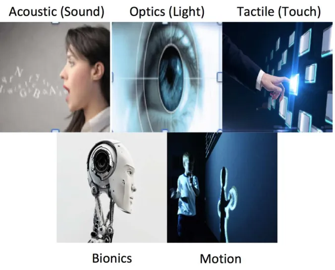
Here, HMIs are introduced into 5 kinds of broad categories, as shown in Figure. 3.1. Each has a unique HMI and will be discussed as follows:
!"#$%&'"()*#$+,-(
./&'"%()0'12&-(
3'#+'"%(
4#&'#+(
56"&'78()5#$"2-(
Figure 3.1: Types of Human Machine Interface
• Optic (Light) based technology
In Optic based technology, normally camera is used as the primary hardware. HMI utilizes camera or similar equipment for computer vision. Lasers and LEDs also can be include into optic area, but normally are used in different way. The advantage of optic based HMI is that it does not require the user to touch anything physically. Movement, hand/face motions or gestures are commonly used to interact with the
device/appliance. Thus, optic based technology can be recognized as an effective public interface.
– Camera - Computer Vision
Base on this vision, hand gesture recognition and tracking, camera recognition and motion analysis are typical usecase. Due to the upwards of millions of pixels, these lead the recognition and tracking possible. These interface can easily be coupled with other technologies to make it more error resistant.
– Laser and LED’s
Laser and LED based technology is normally used for distance detection. Ba-siclly, they are implemented on robots as a backup, or collaborate with other technology, such as camera. The main future of laser or LED is support/-collaborate with other technologies potentially to enhance the human-machine interaction [25].
• Acoustic (sound) based technology
Acoustic based technologies focuses on speech recognition, which convert nature language to computer understood text or equipment understood orders, to control or communicate with devices [2]. The goal of speech recognition is not only transfer the nature language to machine language, also to recognize any human voice with minimal error. Speech recognition has great potential in many fields. Many smart phones or smart devices have already built with voice recognition technologies. Pop-ular acoustic technologies are such as Apple Siri, Google Assistant, Amazon Alexa, etc.
• Bionic technology
Bionic is the most human-like area and provides a lot of cutting edge technology. Bionic technology has been around for a number of years but still not widely used for common daily life except some specific area. It combined with biology, robotics and computer science, in order to provide machine with functional parts, for example. bionic eyes, ears, legs, feet, arms, hands or other human-like parts.
Some of the cutting edge research are list as follows [25]:
– Brain Computer Interface (BCI)
– Myoelectric Interaction (EMG)
– Electrocardiogram (ECG or EKG)
– Electrooculography (EOG)
• Tactile (Touch) technology
Tactile based technology is the only one that requires user to touch/push something physically. The most widely used touch technology is the switch button, such as switch of lighting system. Also, with more function, it provide more powerful skills, such as used on the remote controller, which can be considered as the most useful HMI to control devices. Computer keyboard is also a very useful HMI, is the basic components for any PC.
• Motion Technology
Motion technology normally detect the motion (e.g., movement, hand motion, etc.) to control the machine/device with the already programmed functions to let the automatic operation. It normally is combined with sensors to provide the function services. Thus, the definition of motion technology is used to detect motion which requires user to physically move part of the hardware.
Other interesting motion techiniques are:
– Motion sensing gloves [26]
– Hap-tic feedback device [27]
– 3 dimensional (3D) mouse [28]
Other categories of HMI:
• Command language based interfaces
• Menu-based interfaces
3.3
Classification of HMI for smart home
In my research, for smart home, I will classify all human machine interfaces into 4 main categories, which are tactile user interface, acoustic user interface, motion user interface, and graphical user interface. More detial are described in the following subsections.
3.3.1
Tactile User Interface (TUI)
The definition of TUI for smart home is that based upon the sense of touch (haptic), not relies upon the sense of sight (display technology is not belong to TUI). Typical TUI in smart home are such as switch buttons, remote controllers, keyboard, mouse, touch displays, combination lock, game controllers, and so on. The TUI normally based on the real physical devices, and the location and function of each button of TUI are fixed. TUI normally use the wire cables, or infrared, and so on. To measure the response time and evaluate the delay of TUI, button switch is used (see Figure. 3.2) in this research.
3.3.2
Acoustic User Interface (AUI)
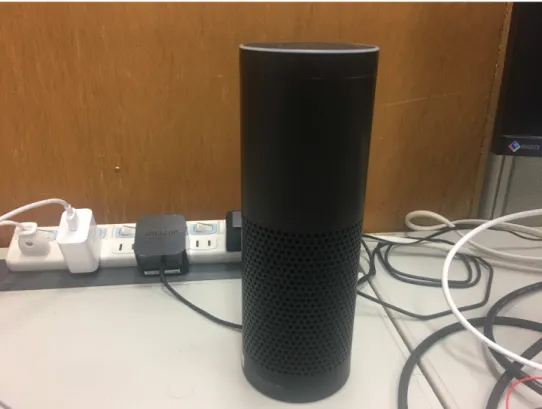
The definition of AUI for smart home is that focuses on speech recognition and speech synthesis, and mutual conversion of input voice and machine language. Famous AUI are such as Siri, Google Assistant, Amazon Alexa, etc. To measure the response time and evaluate the delay of AUI, Amazon echo plus is used in this research (see Figure. 3.3). Alexa is Amazons cloud-based voice service available on tens of millions of devices from Amazon and third-party device manufacturers. With Alexa, you can build natural voice experiences that offer customers a more intuitive way to interact with the technology they use every day.
Figure 3.3: Typical AUI - Amazon Echo Plus
The procedure of speech recognition are list as follows:
• User speak to microphone
• Machine record your voice
• Signal improvement
– Noise reduction and background separation
• Analyze voice
– Pattern recognition
• Feedback to user
If speech recognition can work with high accurately, lot of applications can be con-trolled through AUI, such as controlling your home appliance, lighting system, machine automation, robotics control and others. Some of the applications are:
• voice controlled wheel chairs, voice controlled home appliances [29]
• voice enabled in-car entertainment system [30]
Acoustic based technology is one of the most potential HMI. Although speech recog-nition is not perfect but holds a lot of opportunity for the future, especially for smart home, smart building and smart city. With collaboration with AI technologies, AUI can be recognized as the best way to communicate with machine.
3.3.3
Motion User Interface (MUI)
The definition of MUI for smart home is that based upon resident users’ physically move or rotate by detectors. To measure the response time and evaluate the delay of MUI, wearable MUI is easier than setting a group of different kinds of sensors for detection in this research. Wii controller is one of the most notable motion sensing appliance, which uses infra red sensors and accelerometer to detect motion. Similar with wii controller, the Kymera Magic Wand Remote Control is used (see Figure. 3.3). Other famous MUI for smart home such as Leap Motion, Myo Gesture Control Armband, G-speak, Maestro sensor, singelcue, and so on.
The Kymera Magic Wand Remote Control gives users the opportunity to perform magic in their own home. Kymera Wand is a Universal Remote Control is an advanced,
Figure 3.4: Typical MUI - Kymera Magic Wand Remote Control
gesture based universal remote control, designed to control almost all home entertainment equipment worldwide such as TVs, DVD players, Blue-ray players and iPod docks, using infrared codes learned from conventional remote controls by the means of gestures rather than by pressing buttons.
3.3.4
Graphical User Interface (GUI)
The definition of GUI for smart home is that uses icons, menus and other visual indicator (graphics), displays information and related user controls, manipulates with pointing de-vice. GUI is a type of user interface that allows users to interact with electronic devices through graphical icons and visual indicators such as secondary notation, instead of text-based user interfaces, typed command labels or text navigation. Beyond computers and TV, GUIs are used in many handhold mobile devices such as MP3 players, portable media players, gaming devices (psp, Nintendo Switch, etc.), smartphones and smaller household, office and industrial controls.
Figure 3.5: Typical GUI - Display Screen Smart Phone
A GUI uses a combination of technologies and devices to provide a platform for users to interact with electronic devices, for the purpose of gathering and producing information. A series of elements conforming a visual language have evolved to represent information stored on the device. This makes it easier for people to use it. The most common combination of such elements in GUIs is the windows, icons, menus, pointer (WIMP) paradigm, especially in personal computers, smart phones, tablets and so on. To measure the response time and evaluate the delay of MUI, smart phone/tablet might be the easiest way in this research.
3.4
Timing Issues of MHMI for Smart Home
In previous section, 4 kinds of UI for smart home are introduced, they can be combine together to control the home appliance, which means multimodal HMI. When MHMI is designed for smart home, timing issues are very important. If the timing issues is not considered, synchronization problems might occur, including the delay caused by
!"#$ )&*+$&,,#$%&'(# )&*+$&,,#$-#.&+# /% 012/3$*2&*2+4#2/% 5126$&(#""'*7 812/3$*2&*2+4#2/% 912/%2'"2+3$*#:2&* ;12)<**&+2+&,#$<=,#>2+3$*2&*2+4#2/%2<7<'* ?12/&77,# @12/%2'"2+3$*#:2&AA
Figure 3.6: UML Sequence Diagram on Synchronization Problem of MHMI
the synchronization and the error or collision. Here, an example is given to show the synchronization problem of MHMI.
As we know, the response time of each UI is quite different. Here is an example, user want to turn on the TV. First, user asked Google Assistant/Amazon Echo to turn on the TV, due to the processing of AUI is a little bit long, user wait for a while, then use the remote controller to open the TV directly. However, the TV is turned on, and immediately turned off. To understand the problem more clearly, UML sequence diagram is used to describe the problem (see Figure. 3.6).
A simple way to solve this kind of synchronization problems/timing issues is set the no operation time period. As shown in Figure. 3.7, a middle layer which is called console is set. User want to use AUI to turn on the TV, and after 1 to 2 second, user cannot wait anymore, then use remote controller to do the toggle on the TV again. Console is set that not do the same operation within a fixed time period. Then the concurrency control problem can be solved. MHMI should be designed with these solutions of timing issues rather than ask resident to follow the rules/instructions to operate the home appliance.
!"#$ )&*+$&,,#$%&'(# )&*+$&,,#$-#.&+# )&*"&,# /% 012/3$*2&*2+4#2/% 5126$&(#""'*7 812/3$*2&*2+4#2/% 912/3$*2&*2+4#2/% :12);**&+2+&,#$;<,#=2+3$*2&*2+4#2/%2;7;'* >12/%2'"2+3$*#?2&* @12/&77,# A12BC*(4$&*'D;+'&*
Figure 3.7: UML Sequence Diagram on Synchronization Problem Solution of MHMI
Then, the importance of timing issues on MHMI for smart home is clear. Two step of analysis are necessary before design the MHMI. Firstly, the response time of each UI should be clear. Secondly, the tolerable delay of each UI for most of users should be clear. These works will be explain and setup in the following chapter.
3.5
Discussions
To solve the synchronization with delay or error/collision, several ways are list as follows:
• All of the “toggle commands” should be canceled, which means single operation output only with one command with one single button. This can easily solve the upon problems. However, the problem is that it is impossible to change all of the remote controller with function of “toggle commands”.
we shown in Figure. 3.7. However, all of the operational commands must directly come to the console instead of home appliances. It is difficult to implement.
• If the console is implemented, one more thing is necessary which is the command category. Thus, the objectives of commands from MHMI need to be clear, for exam-ple, multiple commands to single home appliance, multiple commands to multiple home appliances, etc.
Under the console with command category, synchronization problem can be discussed by analyzing the allowable range of delay of each UI. The allowable delay of each UI is discussed in the next chapter.
3.6
Summary
In this chapter, several types of human machine interfaces are introduced. A novel classi-fication of human machine interfaces is defined for smart home, which include TUI, AUI, MUI, and GUI. Moreover, an example is given to show the problem of timing issues when MHMI is designed. To solve the timing issues on MHMI for smart home is not different. However, before design, two kind of time should be measured, which are the response time and tolerable delay of each UI. Based on these measurement, MHMI can provide better quality of experience (QoE) to resident users.
Chapter 4
Timing Issues on each User Interface
In this Chapter, the timing issues on each UI for smart home are described. As I men-tioned in the previous chapter, this measurement and evaluation are important for the design of MHMI in smart home. In another word, it is necessary to analyze and solve the synchronization problem of MHMI and let MHMI more friendly, efficiency and effec-tiveness. The Raspiberry Pi 3 is used for the measurement and evaluation. Typical UI are selected for the measurement and evaluation in last chapter, which are switch button for TUI, Amazon echo plus for AUI, Kymera Magic Wand Remote Control for MUI, and normally Android smart phone for GUI. Depend on the necessary response time of each UI, I add a couple of extra delay for the evaluation of each UI. A questionnaires with absolute category rating is prepared for the evaluation. Based on the results, the time issues of MHMI is discussed.4.1
Introduction
In Chapter 3, typical UI are introduced. For each UI, response time on the operation of home appliance are quite different. Thus, to understood the difference of response time is the first important thing. Here, the experiment target is set as lighting system due to it is basic necessary concept of any home. To design the MHMI for smart home, like [31], the time issues is not considered. Without the discussion of time issues, the implementation
might face the synchronization problems as I discussed in previous chapter. Based on the response time I measured, I set a group of delay and use a questionnaires of ACR to evaluate the tolerable time of each UI. Moreover, based on the difference of tolerable time of each UI, the design of MHMI will be discussed.
4.2
Experiment Setting
To measure the typical response time of each defined UI for smart home, the methodology of the experiment setting is that only the UI parts is different, the rest part should use the same device/situation as possible as we can. In Figure. 4.1, the “RT” is stand for typical respond time, is the time cost between user’s operation and light system’s response action. The experiment environment and experiment devices are described in next section.
!"#$ !""# %"#$ !" $# &"#$ !"%# '"#$ !"&# !"#$ !'""# %"#$ !'" $# &"#$ !'"%# '"#$ !'"&# '()*+"# '()*+$# '()*+&# '()*+%# ()*+),)-.$ $$ $$ $$ $$ $$ /01)22)34$ &556$ 78+-$ 955-$ :86$ $!$ %;($<848=8.)$>?@A$ /01)22)34$ <)28BC$ <)28BD$ E$ &556$ <)28B@$ <)28B+$ E$ 78+-$ <)28BF$ <)28BG$ E$ 955-$ <)28BH$ <)28BI$ E$ :86$ <)28BJ$ <)28B2$ E$ !BK+182$6)28B$5L$)81D$"#$>?CA$ !"#$ (!C$ (!D$ E$ %"#$ (!@$ (!+$ E$ '"#$ (!F$ (!G$ E$ &"#$ (!H$ (!I$ E$ ?C$ ?@$
Figure 4.1: Measurement Methodology of Typical Response Time for each UI
#1 is the experiment for the typical RT. The results are saved into one table which named “Typical delay of each UI”. In #2, extra delay is added to each UI, followed the with five ACR levels, more than 20 reviewers are do the evaluation for each UI. The delays of each UI are saved into the table named with “ACR database”.
4.2.1
Experiment Environment
In this subsection, the experiment environment is introduced. In Figure. 4.2, number 8 is the lighting system, the real light bulb I used in the daily life is used for more accuracy to the real world. Here, number 7 is the relay. The distance between light bulb and reviewers is set as 1.5 meters, which is similar distance from the ceiling to the resident in normal apartment. Number 1 to 4 are the typical UIs which are described in previous chapter. Number 5 is the Raspberry Pi 3, which is the base to combine all of the UI together to control the light system. Number 6 is the WiFi router which provides wireless service to Amazon Echo Plus (number 2), Smart Phone (number 4) and Raspberry Pi 3 (number 5). ! " # $ % & #'( ) * !+(,-../0(12345( "+(6789/0(:;<=(>?-@(16345(
#+(Kymera Magic Wand Remote Control(1A345(
• #'+(BCA8DBEB80( $+(F78C.(>G/0H(1I345( %+(J8@KLHCCM(>B(#(( )+(NBOPB( *+(JH?8M(,/8CQ( &+(RBDG.(
Figure 4.2: Experiment Environment
Figure 4.3: Image of Raspberry Pi and its Block Diagram
in the United Kingdom by the Raspberry Pi Foundation to promote the teaching of basic computer science in schools and in developing countries. All models feature a Broadcom system on a chip (SoC) with an integrated ARM compatible central processing unit (CPU) and on-chip graphics processing unit (GPU). Here, I use Raspberry Pi 3 for the experiment. In Figure. 4.3, the image of Raspberry Pi and its block diagram is shown. GPIO information can be found in Appendix A.
(a) Image of Relay (b) Image of irMagician
Figure 4.4: Other Device for Experiment
A relay is an electrically operated switch (see Figure. 4.4(a)). Many relays use an electromagnet to mechanically operate a switch, but other operating principles are also used, such as solid-state relays. Relays are used where it is necessary to control a circuit
by a separate low-power signal, or where several circuits must be controlled by one signal. Figure. 4.4(b) shows irMagician which is USB controller type infra-red remote con-troller. PIC-18F2550 is main controller for using it. CDC-ACM is used for making connection to major OSs such as Windows, MacOSX and Linux.
4.2.2
Experiment Devices
In this subsection, I list all of the basic experiment devices for the experiment setting (see Table. 4.1). Also, Internet is necessary for the experiment. More detail of each UI settings are described in the following section.
Device Name Number of Devices
Button 1
Amazon ECHO Plus 1
Kymera Magic Wand Remote Control 1
irMagician 1 Smart Phone 1 Raspberry Pi3 1 WiFi router 1 Relay 1 Light 1 Monitor 1 Keyboard 1 Mouse 1
Power Strip several
Breadboard 1
Jumper Wires several
AAA battery 2
Table 4.1: Experiment Devices used for Measurements and Evaluation
4.3
Measurements of typical response time
In this section, the measurements of typical response time are introduced. More detail about the settings, the definition of response time, the function code are described. The delay with red color in all of the figure in this section, is used for the next section for #2.
4.3.1
TUI Settings
In this subsection, the experiment setting of TUI is introduced. As shown in Figure. 4.5, the RT (response time) is defined as:
RTT = tT + tr (4.1)
where tT is the time cost from the action of human to Raspberry Pi try to send the order
to the light system, tr is the time cost from the Raspberry Pi to the light system.
!"#$%&'($)*& !$+,-"))%&./0& '122(3& *"#$%4&&
2
4&2
)&RT
T= t
T+ t
rRDT
T= RT
T+
delay
T456&
Figure 4.5: Experiment Setting of TUI
Figure. 4.5 is the most simple and common way to control the light system at home. In order to implement this function in Raspberry Pi, Python is used. The core part of code are list as follows:
• Definition Parts:
import o s
from time import s l e e p import RPi . GPIO a s GPIO GPIO . setmode (GPIO .BCM)
button =10 % No . 1 0 GPIO i s used .
L i g h t =17 % No . 1 7 GPIO hea der i s used .
GPIO . s e t u p ( button , GPIO . IN , pul l up do wn=GPIO . PUD UP) GPIO . s e t u p ( Light , GPIO .OUT)
• Main Parts: w h i l e ( 1 ) : i f GPIO . i n p u t ( button )==0: p r i n t ( ’ Button was P r e s s e d ! ’ ) o s . system ( ’ date ’ ) i f L i g h t s t a t e==F a l s e : # s l e e p ( 3 )
GPIO . output ( Light , True ) L i g h t s t a t e=True
e l s e :
o s . system ( ’ c l e a r ’ )
# s l e e p ( 3 )
GPIO . output ( Light , F a l s e ) L i g h t s t a t e=F a l s e
4.3.2
AUI Settings
In this subsection, the experiment setting of AUI is introduced. As shown in Figure. 4.6, the RT (response time) is defined as:
RTA = tA+ tr (4.2)
where tA is the time cost from the speech of human to Raspberry Pi try to send the order
to the light system, tr is the time cost from the Raspberry Pi to the light system.
In Figure. 4.6, the processing is a little bit complicate to control the light system at home. The procedure of AUI includes the speaking to ECHO Plus, transmitting speech to Amazon Alexa Skill through WiFi and Internet, recognizing the speeck through Lambda, and then from the Amazon Web Services (AWS) to send the operation command to registered Raspberry Pi, then Node-RED is used to translate the operation command to “0” or “1” to light system.
!"#$%&' !()*#'+,-(('''' .)(#/'0%#12' .#345)11/'6-7' 34)#,' !"#$%&'89:;'6(<3' !"#$%&' =#"52#'''' !"#$%&'>)5'+)1?-@)3' A)?-@)' A%@<")&B' >-CD-' 2)(#/!'
RT
A= t
A+ t
rRDT
A=RT
A+
delay
AB
!'B
1'
!EF'
Figure 4.6: Experiment Setting of AUI
Thus, the first thing is register Raspberry Pi on the Amazon Web Service. Then Raspberry Pi can be recognized and easily controlled through “Alexa” applications. Still, when Raspberry Pi received the command, still need to translate the command to control the light system.
Figure. 4.7 shows the operation on the Node-RED programming tool. Node-RED is a programming tool for wiring together hardware devices, APIs and online services in new and interesting ways. It provides a browser-based editor that makes it easy to wire together flows using the wide range of nodes in the palette that can be deployed to its runtime in a single-click. More information can be found on https://nodered.org/. Under Node-RED, Raspberry received the command (“Turn On Request” or “Turn off Request”) and change it to payload (“True” or “False”), then use the yellow box which named trunonoff to change the “True” or “False” to “1” or “0” to control the GPIO pins. Moreover, the purple box is used to add extra delay for the following ACR evaluation.
Figure 4.7: Operation setting on Node-RED
4.3.3
MUI Settings
In this subsection, the experiment setting of MUI is introduced. As shown in Figure. 4.8, the RT (response time) is defined as:
RTM = tM + tr (4.3)
where tM is the time cost from the action of human to irMagician which connected to
Raspberry Pi, till Raspberry Pi try to send the order to the light system, tr is the time
cost from the Raspberry Pi to the light system.
The procedure of MUI is that Kymera received resident’s movement/gesture, then follow the registered orders to send the IR signal to irMagician. Figure. 4.8 is the very similar
RT
M= t
M+ t
r !"#$%!&!$'( )*+,( -,.$/(0*$"1( -$234,""/(5!6( 7/),"$(#$%!&(8$'1( -,)*9,(:*'9"*.( 1,.$/#(RDT
M=RT
M+
delay
M9
#(9
"(#;<(
Figure 4.8: Experiment Setting of MUI
with TUI settings. In order to implement this function in Raspberry Pi, the core parts of code of Python are list as follows:
• Definition Parts:
import s e r i a l import time import o s
import RPi . GPIO a s GPIO
% s e t t i n g t he d e v i c e , f r e q u e n c y , and time i n t e r v a l s e r = s e r i a l . S e r i a l ( ” / dev /ttyACM0 ” , 9 6 0 0 , t i meo ut =1) GPIO . setmode (GPIO .BCM)
L i g h t =17
GPIO . s e t u p ( Light , GPIO .OUT) GPIO . output ( Light , GPIO .LOW)
L i g h t s t a t e = F a l s e • Main Parts: p r i n t ” Capturing IR . . . ” w h i l e True : s e r . w r i t e ( ” c \ r \n ” ) msg=s e r . r e a d l i n e ( )