Description
of Multilayered
Gamma-Ray
Exposure
Buildup
Factors
up to 40mfp
by the
Approximating
Model
Kazuo SHIN*,t and Hideo HIRAYAMA** * Department of Nuclear Engineering
, Kyoto University ** High Energy Accelerator Research Organization
(Received January 20, 1998)
An approximating formula recently proposed by the authors for g-ray buildup factors of multilayered shields was applied for very thick shields up to 40mfp. For this purpose, modifications were made to the model and
the fitting method to improve the data reproducibility. The previous model was expanded so that it included
both the plane-normal and point isotropic geometries.
The verification test of the modified model was made for three materials; water, iron and lead. The separately published data of double-layered shields for point isotropic buildup factors calculated by EGS4
from 0.1MeV to 10MeV were used as well as newly calculated data at 1MeV for the plane-normal geometry,
and data for the point isotropic geometry of triple-layered shields at 1 and 10MeV.
The present formula generally shows a very good reproducibility of the multilayer buildup factors, even in case of very thick shielding problems. The observed error between the approximating description and the EGS4 data is 15% in the intermediate energy range, about 30% in the higher energy range, and 35% at
0.3MeV. However, the error in the approximation reaches a factor of 4 in the worst case at 0.1MeV.
KEYWORDS: approximation model, point isotropic, plane-normal, gamma radiation, tilayered shields, buildup factor, point kernel, water, iron, lead, energy range, energy
pendence, MeV range 01-10, accuracy
I. Introduction
The point kernel method has been widely used in g-ray shielding design. The shields and equipments used in nuclear facilities are composed of various component ma-terials. Therefore, it has been desired to enable the use of multilayer buildup factors in point kernel codes. Cor-respondingly, many studies(1)-(9) have been conducted to express the multilayered buildup factors by simple ex-pressions so that they may be parameterized by these formulae and incorporated in the point-kernel codes.
These formulae proposed so far(1)-(9) have tried to describe multilayer buildup factors as combinations of those of the composing materials. Unfortunately, the buildup factor in multilayered materials shows a very complex behavior, reflecting changes in the g-ray energy spectrum in the shield from one material to the other. Since the buildup factor of the monolayered shield con-tains only integrated information about the spectrum in the material, the combinations of the buildup factors of monolayered materials can reflect a spectrum change in the multilayered material only in an indirect manner.
As a result, these formulae succeeded in reproducing the multilayer buildup factor only for specific cases.
In our previous papers(10)(11) we proposed a new model having the vector form which explicitly included energy spectrum information in the model. The model was successfully applied to double- and triple-layered shield problems up to 10-mfp (mean free path) thickness at en-ergies from 0.5 to 10MeV.
The objectives of the present study are to make some modifications to the model so that the model may better reproduce reference buildup factors even for very thick shielding problems up to 40mfp, then to test the modi-fied model by using the results of the electron and g-ray shower code EGS4(12) calculations obtained by the new technique(13)(14)
In our previous papers, the approximating model was developed to describe buildup factors of the plane-normal geometry(10) first, and the model was changed to be ap-plied to the point isotropic geometry(11). In the present work, these are unified to a single model that includes the both geometries.
Our approximating description of buildup factors for the point isotropic geometry contains the radius depen-dence of the probabilities of the transmission through and backscattering from a 1-mfp-thick material shell, which has been expressed by simple analytical expres-sions that include empirical parameters. The parame-ters for the albedo were assumed to be common for all
* Yoshida
, Sakyou-ku, Kyoto 606-8501. ** Oho
, Tsukuba-shi 305-0801. t
Corresponding author, Tel. +81-75-753-5825, Fax. +81-75-753-5845,
of the materials(11) to minimize the number of parame-ters. However, errors caused by this assumption was no longer trivial in the case of the very thick shield prob-lems. Therefore, those parameters of the albedos were treated as being material dependent in this work in order to improve the data reproducibility.
The empirical parameters included in the model were determined in previous papers(10)(11) by fitting the ex-pression to buildup factors of double-layered shields. Therefore, the parameters of the three materials were determined in two steps, using the data of the double-layered shields composed of materials 1 and 2, and then those of materials 1 and 3. When the sequence of the fit-ting was changed, the fitted parameters slightly varied, which somewhat affected the composed buildup factors. Here, in the present study, the parameters of three materials were determined simultaneously by fitting the expression to all of the buildup factors of possible combi-nations for double-layered shields of the three materials, i.e. materials 1 and 2, materials 1 and 3, and materials 2 and 3. This process decreases the ambiguity in de-termining the parameters, caused by the selection of the combination of two materials and sequence of the fitting. Finally, the modified model was tested by buildup fac-tors of double-layered shields listed as tables in Ref. (14), where three materials (water, iron and lead) were as-sumed in the calculations. The data at 0.1, 0.3, 0.6, 1, 3, 6 and 10MeV of the point isotropic geometry were utilized. In addition to the above data, buildup factors up to 35-mfp depth at 1MeV of the plane geometry, and those of the point isotropic geometry for 40-mfp-thick triple-layered shields at 1 and 10MeV were generated in this work.
The present paper is organized as follows. Chapter II gives an outline of the present model. Chapter III gives the results of a feasibility test of the model based on the data for 40-mfp-thick shields. The final chapter contains conclusions.
II. Description of Approximation Model of Buildup Factors
1. Outline of the Approximating Model
We use the vector form to express the energy spectrum of g-rays, dividing the energy range from 0 to the source energy (E0) into 4 discrete groups.
A multilayered shield of thickness r of N materials, i.e. n1-mfp-thick material 1, n2-mfp-thick material 2, and so on, is considered. This shield is followed by an infinite medium of material N. In the point isotropic geometry, the shield is a sphere of radius r, and a point isotropic
g -ray source is located at the center of the shield. For the plane geometry, the shield is a plane of thickness r, and a broad beam of g-rays is injected normal to the plane.
The close buildup factor (BD) at depth r is given by
(1)
where S is a source intensity vector, whose explicit ex-pression is S=(1, 0, 0, 0), Tl the transmission matrix of material L, nl is the thickness of the material l in mfp unit, BN the albedo matrix for the outside material (N),
I the unit matrix, and C the conversion vector from the energy-fluence index to the dose index(10)(11).
The transmission matrix (T) is defined with a 1-mfp-thick shell for each material, which depends on the radius of the shell in the point-isotropic case. The matrix is calculated by Tij=fKpij/p11,
(2) where Tij is the ij-element of matrix T, and pij is the group-averaged transmitted flux in the i'th group for the incidence of the j'th group source of the unit intensity. For the detailed definition and assumptions for the cal-culation of pij see Refs. (10) and (11).
The factor K in Eq. (2) is a correction factor for not considering the angular distribution of g-rays in the model, and is given as K is 1 (j=1), a (j=2), b (j=3) and g (j=4), where a, b, g are empirical parameters determined by the least-squares method, so that the ex-pression (1) gives the best fit to the data of the buildup
factors.
The factor f in Eq. (2) is set to be unity for the plane normal geometry, and to be fp for the point isotropic geometry, where fp describes the shell-curvature depen-dence of the g-ray transmission probability in spherical geometry, and is defined as fp=1 (i=1), R1 (i=2, 3), and R2 (i=4). The factors Rl (l=1, 2) are a function of radius that contains two fitting parameters (al and bl)(11).
We approximated(10)(11) the infinite albedo matrix (BN(r)) of Eq. (1) by a finite medium one; a 1-mfp-thick shell of material N which was a spherical shell of a 1-mfp-inner radius in the case of the point isotropic geometry. The ij-element ((BN)ij) of the albedo matrix
is given by
(BN)ij=gSEip B(E)e(E)dE/ei,
(3) where pB(E) is the reflected g-ray flux from the shell, while assuming normal incidence of the j'th-group g-rays of the unity intensity, e(E) is the fluence-to-dose conversion factor at the energy E, and ei an i'th group averaged one of e(E).
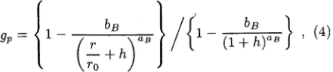
The factor g in Eq. (3) is a geometrical factor so as to modify the calculated albedo matrix to be used for a given depth; g is unity (plane normal geometry), and gp (point isotropic geometry), where gp describes the de-pendence of the albedo on the radius (r) at the given depth in spherical geometry. This is explicitly given by
(4)
where r0 is the 1-mfp-thickness of material N. The parameter h was empirically set as 0.5 in the previous model(11). However, since the albedo should approach to zero when the radius (r) approaches zero, we changed the expression of h in this work so that gp=0 at r=0;
h=b(1/aB)B.
(5)
The empirical
parameters
(aB and bB) are considered
as
material
dependent
in this paper and are estimated
from
the least
squares-fitting
procedure
described
below.
2. Calculation of the Matrices and
Determina-tion of the Empirical Parameters
The group structure
used in this work
is one tested
in Ref. (11). This group
structure
puts more
emphasis
on the higher
energy
range, and the width
of the group
becomes
rather wider
in the lower
energy
range.
With
this group
structure,
we calculated
the
transmis-sion
matrix
using
the EGS4
code(12).
A 1-mfp-thick
slab
was used to calculate
the matrix of the slab geometry,
assuming
a source
of unit intensity
normally
incident
to
the slab. On the other hand, to calculate
the matrix
of the point isotropic
geometry,
a 1-mfp-radius
sphere
was
used,
assuming
a source
of unity intensity
at its
cen-ter. The albedo
matrix
was also calculated
using
EGS4
and the same conditions
as described
above
in the slab
geometry.
In the point
isotropic
geometry,
an albedo
cal-culation
was made for a 1-mfp-thick
shell with an inner
radius
of the 1-mfp
length,
where g-rays
were
injected
normal
to the inner surface.
The obtained
albedo
val-ues were
renormalized
so that the buildup
factor
at the
1-mfp
depth
would
exactly
reproduced
by formula
(1).
Expression
(1) contains
the empirical
parameters a, b
and g included
in K, al, bl (l=1, 2) in Rl, and aB, bB
of Eq. (5). These parameters
are assumed
to be both
material
and energy
dependent.
It is noted that three
materials
(water,
iron and lead) were assumed
in this
work. All of the parameters
were determined
by the
least-squares
method
at each energy
so as to
simultane-ously
fit expression
(1) to the reference
buildup
factors
of all single-
and double-layered
shields
comprising
the
considered
materials.
To determine
the parameters
of materials
1, 2 and 3,
we considered
three combinations
of these
materilas:
ma-terials
1 and 2, materials
2 and 3, and materials
1 and 3.
Also,
for each
of the material
combinations,
we use
ref-erence
data of the four material
configurations
of N-mfp
thickness.
For example,
the configurations
considered
for the combination
of materials
1 and 2 were
single-layered
shields
of both materials,
a double-layered
shield
of the n-mfp
material
1 followed
by material
2, and the
same
thickness
shield
with the reversed
order of the
ma-terial
arrangement.
We prepared
three sets of the
above-mentioned data, where the thickness of the 1st layer was
changed threefolds: n(1), n(2) and n(3) mfp.
We defined the square of the relative difference in buildup factors W by
(6)
where Bm(n')=the buildup factor given by Eq. (1) at a depth of n' mfp; B0m(n')=the corresponding reference data; n'=n(k) to N, representing depths after the terial boundary, where n(k)=1 for the monolayered ma-terials; k=1 to 3, representing the three different first-layer thicknesses; m=1 to 4, representing the above four
material configurations; l=1 to 3, representing the three combinations of materials. The summation on l means the fitting of the buildup factors for all kinds of double-layered shields that can be made up by three materials. The value of W is a function of 27 parameters (a,
b, g, a1, b1, a2, b2, aB and bB) of materials 1, 2 and 3. These 27 parameters were simultaneously changed gradually in a direction where the value W most quickly approached the minimum one until W became less than a predetermined small value.
In all cases of point isotropic sources, we used N=40 and n(1)=5, n(2)=10 and n(3)=20 as described in Ref. (14), whereas N=35 and n(1)=5, n(2)=10 and n(3)=21 were used for the plane source.
III. Application of the Expression to the Multilayer Buildup Factors
1. Application of the Expression to the ered Slab Geometry
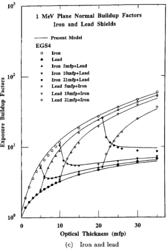
The buildup factors of 1-MeV g-rays normally incident to a slab in the plane geometry were calculated using EGS4 for single- and double-layered shields of material combinations of water, iron and lead, whose total thick-ness was 35mfp and 1st-layer thickthick-ness was 5, 10 and 21mfp. The present approximating model was applied to the obtained buildup factor data. Since the plane ge-ometry was used, the fitting parameters were only a, b and g in the factor K.
The results of the data fitting are given in Figs. 1(a), (b) and (c) for shields composed of water and lead, water and iron, and iron and lead, respectively.
Figure 1(a) shows a comparison of the reproduced buildup factors by the present model along with reference data for the double-layered shields comprising water and lead shields. The data reproduced by the present model agree quite well with those by the EGS4 calculation. In more detail, a discrepancy of 16% at maximum is seen in the data of the shields of 21-mfp water followed by lead. However, the difference in this amount is acceptable for an approximating expression of the buildup factor, which
may be used in routine shielding designs.
Because the albedo of g-rays differs largely between water and lead, the buildup factor of double-layered shields at the material boundaries differs from the corre-sponding values of the monolayered shields. This behav-ior of the buildup factor of the double-layered shields is very well reproduced by the present model.
A comparison of the data reproduced by the present model with the reference ones for shields comprising wa-ter and iron is shown in Fig. 1(b). The overall agreement between them is very good. The largest disagreement of 12% between them is seen in the data of the double-layered shield of 21-mfp water followed by iron. Low-energy g-rays which are built up in the water shield are quickly absorbed in the first few-mfp of a thick shield of iron, which is moderately reproduced by the present model. The 12% discrepancy shown in Fig. 1(b) is not a serious problem for the approximating model. However, if we desire to express the behavior of the buildup factor exactly in this transient region, the number of groups must be increased. The same thing may be pointed out for the similar discrepancy already seen in Fig. 1(a) con-cerning the data of a shield of 21-mfp thick water fol-lowed by lead.
Fig. 1 Plane normal buildup factors at 1MeV for and double-layered shields of water and lead, water
and iron, and iron and lead
Results for shields comprising iron and lead are given in Fig. 1(c), where data based on the present model are compared with the reference data obtained by EGS4. Again, the agreement between them is satisfactory. The maximum amount of disagreement between them is 10%, which is seen at a 35-mfp thickness for a shield of 21-mfp thick iron followed by lead.
2. Application of the Model to Point Isotropic Buildup Factors
The behavior of the buildup factor strongly depends on the g-ray energy, reflecting the change in the linear attenuation coefficient and production rates of secondary photons, such as bremsstrahlung and fluorescence. Cor-respondingly, the g-ray energy where the buildup fac-tor shows typical behaviors can be classified into three regions: low-, intermediate- and high-energy ranges. Therefore, results of an application test of the present model is discussed for each of these energy ranges. (1) Intermediate Energy Range
The energy range from 0.5MeV up to 3.5MeV is the most important one for applying the point kernel method, where major g-ray sources are included. The Compton scattering dominates the g-ray reaction in this energy range, and the linear attenuation coefficient de-creases with rising the g-ray energy. Below 1MeV, the
photoelectric cross section increases quickly with low-ering the energy. Generally, the buildup factor in this energy range becomes larger with decreasing the atomic number.
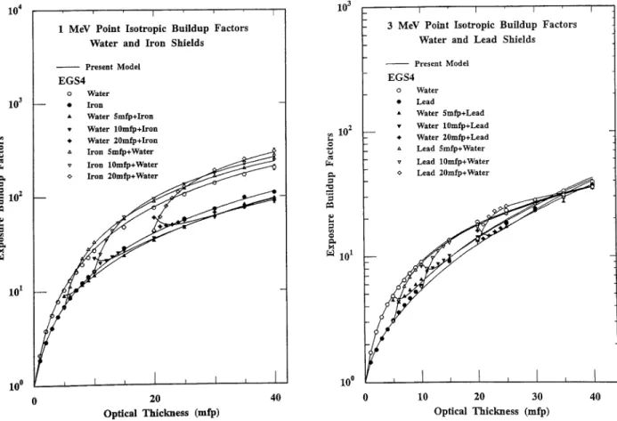
Typical results of the present model in this energy range are shown in Fig. 2 for double-layered shields comprising water and iron at 1MeV. When the figure is compared with the corresponding one of Fig. 1(b) for the plane geometry, a very different behavior of the point isotropic buildup factor is clearly seen.
The length corresponding to 1mfp at 1MeV is very different between water and iron, whereas the difference in the buildup factor is not very large between the two materials. Under this condition, the buildup factors of the double-layered shields of iron followed by water show an excess over the corresponding buildup factor of the water shield, and those of the shields of water followed
by iron fall below the iron data. These behaviors of the reference buildup factors as well as the absolute values are quite well reproduced by the current model.
An example of data fitting by the present model at 3MeV is shown in Fig. 3 for double-layered shields of water and lead. At this energy, the difference in the value of the buildup factor is not large, even between water and lead. A buildup factor of 20-mfp lead fol-lowed by water shows an interesting behavior. When
Fig. 2 Point isotropic buildup factors at 1MeV for and double-layered shields of water and iron
Fig. 3 Point isotropic buildup factors at 3MeV for and double-layered shields of water and lead
the material is switched from lead to water, it increases quickly and goes over the corresponding values of water, then approaches to the buildup factor of water again. All data in the figure are reproduced by the present model quite well, except for the very small discrepancies seen just after the boundaries from water to lead.
In general, the reproducibility of the buildup factor in this energy range by the present model is very good. The maximum observed error of the approximation is about 15% for all of the tested cases of double-layered shields at 0.6, 1 and 3MeV. The error is largest at 0.6MeV, and smallest at 1MeV.
The buildup factors of triple-layered shields were cal-culated using the EGS4 code at 1MeV. The applied shields are of 40-mfp thickness and having the follow-ing configuration: 8-mfp water+4-mfp iron+lead, 8-mfp iron+4-8-mfp lead+water, and 8-mfp lead+4-mfp water+iron. The buildup factors of these shields were re-produced by the present model by using pre-determined
parameters obtained by using the data of double-layered shields. The thus-composed results are compared with the corresponding data of the EGS4 calculations in Fig. 4. It can be seen in the figure that the data of all material configurations are very well reproduced by
the present model, except for a small discrepancy seen near to the material boundaries from lighter materials to lead.
(2) High-Energy Range
In the high-energy range, i.e. Eg>=6MeV, the lin-ear attenuation coefficient of heavy materials, like lead, increases with the g-ray energy due to an increase in the pair-production cross section. Therefore, scattered photons down to the Compton minimum energy have a greater probability of penetration through the shield than do photons at the source energy. Moreover, the bremsstrahlung production cross section is fairly large for high-energy electrons in lead. This increases the number of photons near and below the Compton minimum en-ergy. It is noted that the critical energy in lead is 7MeV, which means that the multiplication of photons may take place by a cascade reaction at 10MeV in the lead shield. Consequently, the buildup factor in lead becomes very large at deep locations. In general, the buildup factor in this energy range becomes larger in the order of the atomic number of the material, which means that the buildup factor of water is the smallest of water, iron and lead.
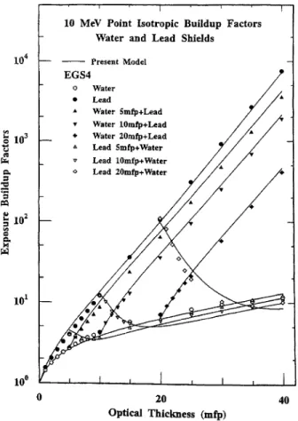
The results of the present model at 10MeV are com-pared with the reference data of EGS4 in Fig. 5, where the buildup factors of shields comprising water and lead are shown. The buildup factors in the lead shields, both
Fig. 4 Point isotropic buildup factors at 1MeV for mfp thick triple-layered shields, water+iron+lead , iron+lead+water and lead+water+iron , whose 1st layer thickness is 8mfp and 2nd layer thickness is
4mfp
Fig. 5 Point isotropic buildup factors at 10MeV for and double-layered shields of water and lead
in the single- and double-layered shields, increase very quickly with increasing the lead thickness. This behav-ior of the buildup factor in the lead shield is very well reproduced by the present model in Fig. 5.
However, the buildup factor in the water shield is slightly underestimated by the present model, espe-cially in double-layered shields. The maximum amount of the discrepancy observed between the two data is -30%, which is observed at 6-20mfp thicknesses in wa-ter shields. The g-ray spectrum in lead is very soft, com-pared with the hard spectrum in water. This spectrum change from lead to water may not be very well repro-duced by the present model, because of the 4-group ap-proximation.
The point isotropic buildup factors at 10MeV of triple-layered shields were calculated using EGS4. The shields considered were 8-mfp water+4-mfp iron+lead, 8-mfp iron+4-mfp lead+water, and 8-mfp lead+4-mfp water+iron. The parameters already determined using the data for the double-layered shields were used in the present model to compose the buildup factors of the triple-layered shields.
The thus-obtained results are compared with the cor-responding ones from EGS4 in Fig. 6. The buildup fac-tors of the triple-layered shields based on the present model agree quite well with those from the EGS4 calcu-lation except for at around 20mfp in water of a shield of iron+lead+water, where the present model mates the buildup factor by about 30%. This underesti-mation corresponds to the underestiunderesti-mation seen for the double-layer data in the water region of Fig. 5.
The behaviors of the buildup factors at 6MeV were quite similar to those at 10MeV. However, the repro-ducibility of the data by the present model was improved. The underestimation observed in the water shields was resolved at 6MeV.
(3) Low-Energy Range
In the low-energy range, i.e. 0.1 and 0.3MeV, the absorption cross section is generally very large, except for light materials. This causes a hardening of the g-ray spectrum in the shields, and almost no g-rays exist in the 4th group. Corresponding to this, the correction factor (fp) defined in Sec. II-1 is changed in this energy range: fp=1 (i=1), R1 (i=2), R2 (i=3), and 1 (i=4).
On the other hand, in the water shield, low-energy g-rays buildup in the 4th group very quickly, which results in large values of the buildup factor at deep locations. Nevertheless, the above definition of fp is also used for water. Generally, the characteristics of the buildup fac-tor differ very much in this energy range, depending on the material. It should be noted that when the original definition of fp was used instead of the above one, the obtained results were similar to, but slightly worse than those given by the above one. All of the data described below were fitted results with fp as defined above.
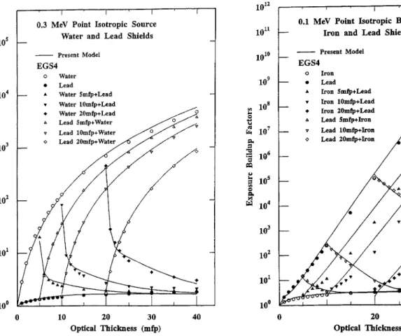
An example of the results of the present model at 0.3MeV is shown in Fig. 7 for shields comprising wa-ter and lead. The wawa-ter buildup factor becomes as large
as 5x10³ at 40-mfp depth, whereas that of lead stays at about 2, even at the deepest location. The reproducibil-ity of the data based on the present model is satisfactory.
In the case of double-layered shields of iron and lead, an about -35% disagreement, which was the largest er-ror observed of all cases at 0.3MeV, was seen between the present model and the reference data in the lead shields behind iron.
It was already reported(2) that the buildup factor of lead at 0.1MeV increased very quickly with increasing the lead thickness, and reached a value of as large as
-1011 at 40-mfp thickness. On the other hand, the buildup factor of iron at the same energy remained at a very small value, even for a very thick shield. The water buildup factor at this energy becomes as large as 3x10⁴ at 40-mfp thickness, and much larger than at higher en-ergies.
These extreme behaviors of the buildup factor were caused by changes in the g-ray spectrum in the shields. The intense absorption characteristics remove low-energy
g
-rays in iron, and form the very hard spectrum, whereas in water, the low-energy g-rays buildup greatly, due to the low absorption cross section. The existence of the K-and L-edges, and the production of fluorescences changes
Fig. 6 Point isotropic buildup factors at 10MeV for mfp thick triple-layered shields, water+iron+lead, iron+lead+water and lead-water+iron, whose 1st
layer thickness is 8mfp and 2nd layer thickness is 4mfp
the situation very differently in lead, where the produced secondary photons penetrate the lead shield via the cross section windows just below the edges.
As explained, the spectrum difference of g-rays in these materials is very large at 0.1MeV, and the few group spectrum expression of the present model may no longer be valid. Therefore, it is interesting to test whether or not the present model works at 0.1MeV.
The buildup factor for the combination of iron and lead is shown in Fig. 8, which is the most extreme case that the material having the largest buildup factor of
-1011 at 40mfp is combined with iron of the smallest buildup factor as low as about 4 at the same depth. In this case, the buildup factors in iron in double-layered shields of lead followed by iron decrease moderately to those of the iron monolayer. These buildup factors are quite well reproduced by the present model.
However, the buildup factors in lead in the double-layered shields of the reversed material order are over-estimated by the present model by a factor of 2-4. The
g -ray spectrum in iron has the largest value at the source energy, and decreases quickly with decreasing the g-ray energy. On the other hand, although very big peaks exist in the lead spectrum due to the K-X rays of -89keV, the spectrum value above this energy is very small. There-fore, regarding the EGS4 results the g-ray buildup in the lead starts with some delays behind the material
boundaries after g-rays near to the source energy are scattered down to an energy range below the K-edge. In the present model, the region above 80keV up to 99keV is in the same energy group, and the above-mentioned detailed spectrum difference between iron and lead is not described. The increase in the buildup factor starts in lead just after the material boundary, which leads to an overestimation of the buildup factor. The increase in the energy group number at a higher energy range is needed to improve the reproducibility of the buildup factors.
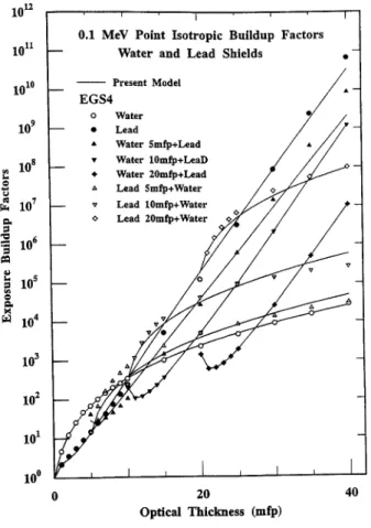
The buildup factors are shown in Fig. 9 for the com-bination of water and lead, which is an example of the extreme behaviors of the buildup factor at 0.1MeV. In this case, the overall agreement of the data between the present model and the EGS4 calculation is better than that for the combination of iron and lead. This is be-cause the energy spectrum of g-rays in both lead and water spreads in wider energy groups than in the iron shields, and the spectrum variation between the two ma-terials is better described by the present model.
Interesting behaviors of the buildup factor are pointed out for the double-layered shields. The buildup factor in the 2nd layer of water followed by lead once decreases just behind the material boundary, then starts increasing quickly with the lead thickness. The temporary decrease in the buildup factor is caused by the cutoff of the very
Fig. 7 Point isotropic buildup factors at 0.3MeV for and double-layered shields of water and lead
Fig. 8 Point isotropic buildup factors at 0.1MeV for and double-layered shields of iron and lead
low-energy part of g-rays that had built up in water. A reversed behavior is seen in the buildup factor of the shields of lead, followed by water, where a temporary ex-cess of the buildup factor to the corresponding data of the lead monolayered shield occurs. The latter behav-ior is caused by the disappearance of strong absorption at very low energies when the material is changed from lead to water. It should be noted that these interesting behaviors of the buildup factor are very well reproduced by the present model.
IV. Conclusion
Our modified approximating model of the multilayer g
-ray buildup factor was tested based on the reference buildup factor data estimated by using EGS4 for very thick shields of up to 40mfp.
As a conclusion of the tests, it is pointed out that the present approximating model generally has a very good capability to reproduce the multilayer buildup factors, even in very thick shields. The observed error was within 15% in the intermediate energy range, about 30% in the higher energy range, and 35% at 0.3MeV.
At a very low energy of 0.1MeV, the error of the ap-proximation reaches a factor of 4 in some cases. However, this error is acceptable as an approximating formula of the buildup factor, considering a very large change of
-1011 in the buildup factor.
In the next step, the possibility of interpolating the parameters and the matrices with the g-ray energy and the Z-number of materials should be tested. Then, a systematic parameterization of the buildup factors will be started for major shielding materials. In parallel with these studies, we will incorporate the current expression into a point kernel code.
Fig. 9 Point isotropic buildup factors at 0.1MeV for single-and double-layered shields of water and lead
-REFERENCES-(1) Su, M. F., Jiang, S. H.: Gamma-ray buildup factors for a point isotropic source in stratified spherical shields, Nucl. Sci. Eng., 102, 64 (1989).
(2) Harima, Y., Hirayama, H.: Detailed behavior of expo-sure dose buildup factor in stratified shields for plane-normal and point isotropic sources, including the effects of bremsstrahlung and fluorescent radiation, Nucl. Sci. Eng., 113, 367 (1993).
(3) Kitazume, M.: Some considerations of buildup fac-tors in gamma-ray penetration for multilayers, Nihon-Genshiryoku-Gakkai Shi (J. At. Energy Soc. Jpn.), 7, 496 (1965), [in Japanese].
(4) Harima, Y., Nishiwaki, Y.: An approximate transmis-sion dose buildup factor for stratified slabs, J. Nucl. Sci. Technol., 6, 711 (1969).
(5) Bowman, L. A., Trubey, D. K.: Monte Carlo calcula-tion of gamma-ray dose-rate buildup factors for lead and water shields and Monte Carlo calculation of the deposition of gamma-ray heating in stratified lead and water slabs, ORNL-2609, (1958).
(6) Kalos, M. H. quoted in Goldstein, H.: "Fundamen-tal Aspect of Reactor Shielding", Addison-Wesley Publ. Reading, Massachusetts, p. 225 (1959).
(7) Broder, D. L., Kayurin, Yu. P., Kutrezov, A. A.: Trans-mission of gamma radiation through heterogeneous me-dia, Sov. At. Energy, 12, 26 (1962), [English Transla-tion].
(8) Penkuhn, H.: A parametric representation of gamma-ray attenuation in two-layer shields, Nucl. Sci. Tech-nol., 1, 809 (1979).
(9) Harima, Y., Hirayama, H., Tanaka, S., Sugiyama, M.: The behavior of gamma-ray buildup factors in stratified shields, Proc. Topical Meeting New Horizons in Radi-ation Shielding, Pasco, Washington, April 26-May 1, 1992, p. 473 (1992).
(10) Shin, K., Hirayama, H.: A new approximating model for gamma-ray buildup factors of stratified shields, Nucl. Sci. Eng., 118, 91 (1994).
(11) Shin, K., Hirayama, H.: Approximating model for mul-tilayer gamray buildup factors by transmission ma-trix method: Application to point isotropic source ge-ometry, Nucl. Sci. Eng., 120, 211 (1995).
(12) Nelson, W. R., Hirayama, H., Rogers, D. W. O.: The EGS code system, SLAC-265, (1985).
(13) Hirayama, H.: Calculation of gamma-ray exposure buildup factors up to 40mfp using the EGS4 Monte Carlo code with a particle splitting, J. Nucl. Sci. Tech-nol., 32, 1201 (1995).
(14) Hirayama, H., Shin, K.: Application of the EGS4 Monte Carlo code to a study of multilayer gamma-ray exposure buildup factors up to 40mfp, J. Nucl. Sci. Technol., 35, 816 (1998).