Handover Management for VoWLAN Based on Estimation of AP Queue Length and Frame Retries
10
0
0
全文
(2) IEICE TRANS. INF. & SYST., VOL.E92–D, NO.10 OCTOBER 2009. 1848. proposed HO strategy. Finally, concluding remarks are presented in Sect. 6. 2.. Existing Studies of Handover Strategy. Many HO decision strategies have been studied for various layers of the protocol stack where network and transport layers are most widely studied. Mobile IP [1] is a network layer scheme utilizing and relying on network infrastructures including Router advertisement, Home Agent (HA) and Foreign Agent (FA). However, an HO process in Mobile IP takes a significant time period including the period for acquisition of the IP address in a new WLAN and registration request to an HA and a Correspondent Node (CN). For example, the layer 2 handover period is 50–400 ms [2], acquisition of IP address from DHCP takes about 300 ms, and registration request is one way delay. Therefore, it is clear that aggregation of interruption period of layer 2 and 3 contributes to deterioration of VoIP communication quality. Moreover, although FMIPv6 [3] and HMIPv6 [4] have been proposed to reduce the handover processing period, they are difficult to deploy in WLANs administrated by different organizations. This is because they require additional network element such as the HA that introduce a burdensome administration and require additional cost. Then, we consider the end-to-end basis approach, which is not require any change of network infrastructure. On the transport layer, mobile Stream Control Transmission Protocol (mSCTP) [5], which is a mobility extension of SCTP, has been proposed. Although mSCTP supports multi-homing and dynamic address reconfiguration for mobility, the issue of the HO decision is not discussed in detail. The authors in [6] proposed an SCTP based HO scheme for VoIP using a Mean Opinion Score (MOS) [7] as an HO decision metric. The HO mechanism employs a probe message called a heartbeat to estimate a Round Trip Time (RTT) and then calculates MOS value based on the RTT. However, since upper layer (above layer 3) information such as packet loss, RTT, and MOS indicate end-to-end communication quality, the information is varied due to both the wireless and wired networks. Therefore, the existing studies could cause unnecessary HOs due to temporal congestions in wired networks. In a mobile environment, MNs need to promptly and reliably detect wireless link condition. Our practical experiments in [8] proved that the number of frame retries on the MAC layer has the potential to detect the wireless link degradation during movement because packets over WLAN inevitably experience frame retries before being treated as packet loss. Reference [9] proposed an HO mechanism employing the number of frame retries as an HO decision metric through analytical study. This method, however, only considers the frame retransmission caused by the collision with frames transmitted from other MNs in a noninterference environment. On the other hand, we proposed an HO strategy method considering the number of data frame retries on the MAC layer [10]–[12]. This strategy. employs multihoming enabling to execute multi-path transmission mode for supporting inter-domain soft-HO between two WLANs with different IP subnets. However, although our previous method can detect the degradation of wireless link condition due to both movement of MN and radio interference, it cannot detect congestion at both serving AP and targeted AP. This is because our previous method detects wireless link condition based on only data frame retries without considering congestion at both serving AP and targeted AP. Therefore, in our previous method, an MN could execute an HO to a congested AP as well as leads to imbalanced traffic load among APs, thus, VoIP quality would be degraded. We need an HO strategy considering congestion of AP and the load balancing among the APs. In [13], authors proposed a decentralized AP selection strategy to achieve a load balancing among the APs by exploiting the packet error rate that can be obtained from the RSS. However, this strategy only considers TCP traffic and it requires a slight modification in both MN and AP. We consider an HO strategy based on end-to-end basis for realtime application and the HO strategy aim no modification of network infrastructure such as AP. In this paper, we propose an HO strategy considering congestion of both targeted AP and serving AP in addition to wireless link condition in order to avoid VoIP quality degradation and achieve a load balancing among APs. 3.. Handover Decision Metrics. We discuss HO decision metrics that can precisely indicate wireless network condition. In particular, many HO technologies employ the RSS on PHY layer as an HO decision metric. However, our previous research [8] shows that RSS is very difficult to use to properly detect deterioration in communication quality because it fluctuates abruptly due to distance and interfering objects. It also cannot detect the degradation due to radio interference. Furthermore, in [8], we showed that the information of the MAC layer, i.e., frame retry has the potential to serve as a significant metric. However, it cannot satisfactorily detect the wireless networks condition. In this section, we then describe the following three HO metrics employed in our new proposed method. 3.1. RTS Frame Retries. In the IEEE802.11 standard, a sender confirms a successful transmission by receiving an ACK frame in response to the transmitted data frame. When a data or ACK frame is lost, the sender periodically retransmits the same data frame until achieving a successful transmission or reaching a predetermined retry limit. The standard supports two retry limits: long-frame and short-frame retry limits. In addition, the standard also includes the Request-to-Send (RTS)/Clear-toSend (CTS) function to prevent collisions caused by hidden nodes. If RTS/CTS is applied, a long-frame retry limit of.
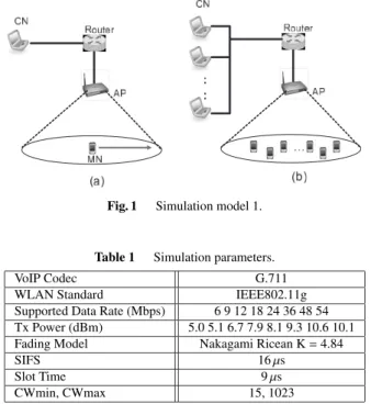
(3) NISWAR et al.: HANDOVER MANAGEMENT FOR VOWLAN BASED ON ESTIMATION OF AP QUEUE LENGTH AND FRAME RETRIES. 1849. Fig. 1. Table 1. Simulation model 1.. Simulation parameters.. VoIP Codec WLAN Standard Supported Data Rate (Mbps) Tx Power (dBm) Fading Model SIFS Slot Time CWmin, CWmax. G.711 IEEE802.11g 6 9 12 18 24 36 48 54 5.0 5.1 6.7 7.9 8.1 9.3 10.6 10.1 Nakagami Ricean K = 4.84 16 µs 9 µs 15, 1023. four is applied, otherwise, a short-frame retry limit of seven is applied. When frame retries reach the retry limit, the sender treats the data frame as a lost packet. That is, we can detect the occurrence of packet loss in advance by utilizing the frame retries. Moreover, unlike the RSS, frame retries can promptly and reliably detect the wireless link degradation due to not only reduction of signal strength but also radio interference and collisions [8]. Therefore, frame retry allows an MN to detect wireless link condition promptly and reliably. In [10], we employed data frame retry as an HO decision metric in WLANs with a fixed transmission rate (11 Mb/s). However, in a real environment, almost all WLANs employ a multi-rate function that can change the transmission rate according to wireless link condition. If the transmission rate is dropped by the multi-rate function, a more robust modulation type is selected and thus data frame retries are further decreased. As a result, an MN cannot properly detect the degradation of wireless link quality only from data frame retries in multi-rate WLANs. We then consider an RTS frame as an alternative metric of data frame retries. As an RTS frame is always transmitted at the lowest rate (e.g., 6 Mb/s in 802.11a/g and 1 Mb/s in 802.11b), an MN can appropriately detect the change of wireless link quality. Moreover, RTS frame is basically employed to prevent collisions in wireless network due to hidden nodes. However, according to the IEEE802.11 standard, as RTS threshold is 2347 bytes by default, thus, RTS is not sent in case of VoIP packet size (160 bytes). Therefore, in our proposal, all MNs must set RTS threshold to 0 in order to enable the MNs send the RTS frame. To show the effectiveness, we investigate the behavior of the RTS retry ratio when an MN moves away from an AP through simulation experiments using Qualnet 4.0.1 [14]. Figure 1 (a) and Ta-. Fig. 2. RTS retry rate vs. MOS over distance.. ble 1 show a simulation model and parameters, respectively. Note that we employ MOS [7] to assess the VoIP quality. In our study, RTS retry ratio is employed instead of the frequency of RTS retries. The RTS retry ratio is calculated as follows: RTS Retry Ratio =. Number of RTS Frame Retries (1) Total Transmitted Frames. The number of RTS frame retries and the total transmitted frames are calculated at every distance point. Figure 2 shows the relationship between the MOS and RTS retry ratio as a function of distance between the AP and the MN. Note that MOS of more than 3.6 indicates an adequate VoIP call quality. From Fig. 2, we can see that the MOS is degraded with the increase in the RTS retry ratio when the MN moves away from the AP. Since the RTS retry ratio is varied due to the fluctuation of wireless link quality, we employ a least-squares method to grasp their trend and estimate the best fit of the occurrences of RTS retry ratio over the distance, shown as a straight line. The straight line shows that the RTS retry ratio of 0.6 indicates the starting point of VoIP quality degradation. Therefore, we set the RTS retry ratio of 0.6 as one of the thresholds to execute the HO in this study. 3.2. AP Queue Length. With the increase of VoIP calls in a WLAN, the AP queue length increases. Then, each packet routed to MN and queued in the AP buffer may experience a large queuing delay or packet loss due to increase in queue length or buffer overflow. Consequently, the queuing delay and the packet loss severely affect the VoIP quality of MNs. However, the IEEE802.11 (a/b/g/n) standard unfortunately does not provide a mechanism that can inform MNs of the AP queue length. Therefore, to maintain VoIP quality, an MN needs to detect the congestion of the AP by itself. We then investigate the relationship between the number of MNs (VoIP calls) and AP queue length through simulation experiments. Figure 1(b) and Table 1 show a simulation model and parameters, respectively. In the simulation scenario, we randomly locate from one to 18 MNs in a WLAN. Each MN communicates with a CN using VoIP. Figure 3 shows the relationship among the number of MNs,.
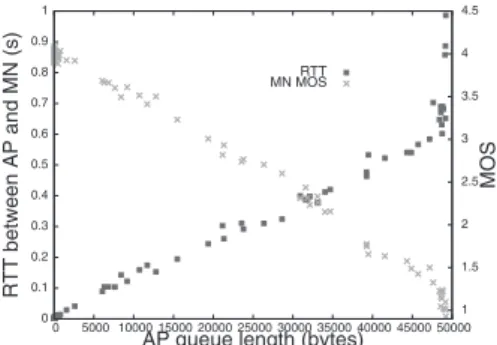
(4) IEICE TRANS. INF. & SYST., VOL.E92–D, NO.10 OCTOBER 2009. 1850. Fig. 3. Relationship among # of MNs, AP queue length, and MOS.. Fig. 4. Fig. 5. Fig. 6. RTT between AP and MN (W-RTT).. AP queue length, and MOS. From Fig. 3, we can see that although VoIP quality of CNs (CN MOS value) is kept adequate even if VoIP calls increase, the MN MOS value adversely degrades. From Fig. 3, we found the significance of the AP queue length. However, how can MNs detect AP queue length without modifying an AP? Therefore, we propose a method to estimate AP queue length based on RTT between MN and AP. Note that in this paper, the RTT between MN and AP is called Wireless RTT (W-RTT). As illustrated in Fig. 4, the MN periodically sends a probe packet (ICMP message) to an AP and then calculates W-RTT. The W-RTT increases in response to the increase of AP queuing delay because a probe response packet experiences queuing delay in the AP buffer. Therefore, the W-RTT can be used to derive information about AP queuing delay. We then investigate the relationship among MOS, AP queue length and the W-RTT using the simulation model in Fig. 1 (b). From Fig. 5, we can see that the W-RTT increases with the increase of AP queue length and the AP queue length of less than 7,500 bytes satisfies an adequate VoIP call. The graph also shows that the W-RTT should be kept under 200 ms to satisfy adequate VoIP quality. Therefore, in our proposed method, we employ W-RTT to estimate AP queue length and set the W-RTT threshold (W-RT T thr) of 200 ms to maintain the adequate VoIP quality.. Relationship among AP queue length, W-RTT, and MOS.. 3.3. Proposed HO architecture.. Transmission Rate. IEEE 802.11 supports a rate adaptation function that can dynamically and automatically change the transmission rate based on wireless link condition. In the case where wireless link quality degrades, as the transmission rate decreases caused by the change of the modulation type, the wireless resource is more occupied because of the long transmission delay. As a result, the lower transmission rate is likely to cause congestion of an AP. Therefore, to alleviate congestion of an AP, the transmission rate can also be treated as a potential HO decision metric. 4.. Proposed Handover Strategy. In our study, we employ RTS frame retry, estimation of AP queue length (W-RTT), and transmission rate as HO decision metrics. We then propose an HO strategy method based on [10]. In [10], an MN has two WLAN interfaces (IFs), and an HO Manager (HM) implemented on transport layer controls HO based on the HO decision metrics obtained through cross layer approach (see Fig. 6). 4.1. Single-Path and Multi-Path Transmission. Our proposed HO method employs multi-homing similar to.
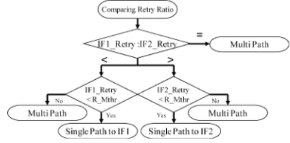
(5) NISWAR et al.: HANDOVER MANAGEMENT FOR VOWLAN BASED ON ESTIMATION OF AP QUEUE LENGTH AND FRAME RETRIES. 1851. Fig. 7. Switching to single/multi-path transmission.. [10] in order to support soft-HO. HM properly switches between single-path and multi-path transmission modes in response to wireless network condition. Single-path transmission mode means that an MN communicates with a CN using only one IF. Multi-path transmission, on the other hand, means that an MN sends duplicated packets to a CN through two IFs for supporting soft-HO. Figure 7 shows an algorithm of switching to single/multi-path transmission when an MN moves into an overlap area of two APs (AP1 and AP2). An MN associated with two APs transmits a probe packet to both APs at 500 ms intervals to estimate AP queue length of each AP. If both WRTT values are below an W-RTT threshold (W-RT T thr), an MN detects that both APs are not congested. Then, the MN investigates the RTS frame retry rate of the current (single) active IF since its movement also affects wireless link condition. If the RTS frame retry ratio reaches a retry ratio threshold of single-path (R S thr), an HM switches to multipath mode to investigate the wireless link condition of both IFs as well as supporting soft-HO. On the other hand, if the W-RTT of AP1 reaches W-RT T thr, i.e., detection of congestion at AP1, an MN switches to the AP2 directly without switching to multi-path mode because multi-path mode may cause more serious congestion in WLANs. Finally, if both measured W-RTTs reach W-RT T thr, an MN then investigates the wireless link condition by using the RTS frame retry ratio of the active single IF. In multi-path transmission, to maintain VoIP quality, an MN sends the same data packets to both IFs. Hence, the MN needs to switch back to single-path transmission as soon to prevent redundant network overload. As shown in Fig. 8, an algorithm of switching to single-path transmission works as follows. An MN measures W-RTTs of both APs at all times. If either of the W-RTTs is below the W-RT T thr, the MN switches to an IF with the smaller W-RTT. If both W-RTTs are simultaneously below the W-RT T thr, the MN then compares the RTS frame retry rate of both IFs. Figure 9 shows an algorithm to compare RTS frame retry ratios of both IFs. If both frame retry ratios of the IFs are equal, the MN continues multi-path mode. On the other hand, if either of the frame retries is below the ratio threshold of multi-path (R Mthr), the MN switches to single-path mode. Fig. 8 sion.. Switching from multi-path transmission to single-path transmis-. Fig. 9. HO based on RTS retry ratio.. through the IF with the smaller frame retry ratio. Note that, this proposed method is further called the basic method. 4.2. Dealing with Ping-Pong Effect (Extension Method 1). If all MNs send probe packets to measure the W-RTT in the basic method, the MNs may unfortunately detect congestion of the serving AP (e.g., AP1) at nearly the same time. Then, all MNs may switch the communication to a neighbor AP (e.g., AP2) and leave AP1. As a result, the neighboring AP2’s queue length is drastically increased, and then, all MNs switch back to AP1 again. This phenomenon is typically known as the ping-pong effect and leads to degradation of all VoIP quality due to fluctuation of both APs queue length. To avoid the ping-pong effect, we extend the basic method. In extension method 1, to avoid the simultaneous HO among all MNs, they first examine their own current transmission rate before executing HO. Figure 10 shows an HO algorithm based on transmission rate. A WLAN provides a multi-rate function that can change the transmission rate dynamically based on wireless link condition. As mentioned earlier, since an MN with lower transmission rate occupies a large amount of wireless resources, the MN is liable to lead to congestion of an AP. Moreover, as MNs with the lowest transmission rate typically are far away from the connected AP, that is, near the edge of its coverage, they must execute handover as soon as possible to maintain their communication quality. Therefore, in extension method 1, MNs with the lowest transmission rate (6 Mb/s) first execute HO. Then, if the AP queue length is still high even.
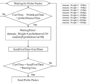
(6) IEICE TRANS. INF. & SYST., VOL.E92–D, NO.10 OCTOBER 2009. 1852. Fig. 10. HO based on transmission rate.. after T ime thr, MNs with the next lowest transmission rate (12 Mb/s) start to execute HOs. The extension method 1 actually works as follow. When the serving AP is congested, all MNs detect the congested AP through RTT measurement (W-RT T > W-RT T thr). First, all MNs with transmission rate of 6 Mb/s (the lowest rate) execute the HO since ARF thr is set to 0 by default. Note that ARF thr of 0 indicates 6 Mb/s. After that, if the AP is still congested in T ime thr, the all remaining MNs increase the ARF thr by one, i.e., the ARF thr of one indicates 9 Mb/s. Then, MNs with transmission rate under 9 Mb/s execute HO. This handover process is repeated until congestion of the AP is alleviated. If the congestion is alleviated, ARF thr of all MNs set back to default value of 0. Thus, an MN does not need to know whether another MN with lower transmission rate has executed the HO or not. Therefore, to execute HO, all MNs only monitor their own transmission rate and compare the rate with the current ARF thr. 4.3 Elimination of Redundant Probe Packets (Extension Method 2) If every MN measures W-RTT by using probe packets according to extension method 1, these probe packets may aggravate congestion in a WLAN. To eliminate the redundant probe packet, we further extend the extension method 1. In extension method 2, only one representative MN sends a probe packet to the AP, and then other MNs measure WRTT by capturing the probe and probe ACK packets that the representative MN sends and receives, respectively. This method works as follows (see Fig. 11). Each MN first monitors all packets over a wireless link before sending a probe packet by itself. If it receives a probe packet sent by another MN, it cancels the transmission of a probe packet and measures W-RTT by using the probe and probe ACK packets, which another MN exchanges. Each MN can then identify whether a captured packet is a probe packet or not, by observing the ICMP message frame length (64 bytes). Furthermore, an MN can also identify whether a probe packet is for request (ICMP Request) or for reply (ICMP Response) by observing the MAC address of the captured ICMP packet because all MNs connected to an AP can. Fig. 11. Fig. 12. Calculate W-RTT from existing probe packet.. Obtaining a right to send the probe packet.. identify the MAC address of the AP. If the destination MAC address of the captured packet is that of the AP, each MN can judge the packet as a probe request packet. On the other hand, if the source MAC address is an AP’s, then each MN judges the packet as a probe reply packet. In Fig. 11, probeReq T ime and probeReply T ime are the receiving time of the probe request transmitted from another MN and that of the probe reply transmitted from the AP, respectively. As every MN can identify whether a captured packet is a probe request or probe reply, it can calculate the W-RTT (probeReply T ime− probeReq T ime) properly. In this way, this method can eliminate the redundant probe packets because MNs calculate the W-RTT by capturing the probe packets that one representative MN sends. If the representative MN leaves a WLAN, one of the remaining MNs needs to start periodically sending a probe packet as a representative MN. Here, we describe how an MN obtains the right to send probe packets in Fig. 12. First, all MNs always examine the difference between the last receiving time of a probe packet (ProbeLastT ime) and the current time (CurrT ime). If the difference is greater than probeAbsenceT ime, that is, a probe packet can not be cap-.
(7) NISWAR et al.: HANDOVER MANAGEMENT FOR VOWLAN BASED ON ESTIMATION OF AP QUEUE LENGTH AND FRAME RETRIES. 1853. tured for a while, first, MNs with the lowest transmission rate in a WLAN try to send a probe packet. This is because a probe packet sent at the lowest transmission rate can be captured by almost all MNs in a WLAN due to its inherently longer transmission range. The timing to send a probe packet among MNs is determined based on WaitingT ime. Basically, an MN with the smallest WaitingT ime, will be a representative MN because WaitingT ime is calculated based on datarate Weight, which indicates its weight of transmission rate (see Fig. 12). Thus, if the datarate Weight is lower, then WaitingT ime gets small. If several MNs with the same transmission rate are existed, then random value in WaitingT ime helps to distinguish who will be the representative MN among them. 5.. Performance Evaluation. We evaluate our proposed HO schemes through simulation experiments. We implement our proposed methods in Qualnet simulator 4.0.1 [14]. Tables 1 and 2 show the simulation parameters and system parameters, respectively. In our study, we employ MOS to assess the VoIP quality.. in the AP2 coverage area. That is, each MN may have a different transmission data rate according to its location. We employ a G.711 VoIP codec that sends a 160-byte packet at 20-ms intervals. We execute 200 simulations with different seeds, and each simulation time is 100 seconds. Thus, our simulation results indicate the average value of the simulations. To show the effectiveness of estimation of AP queue length, we compare our basic method with our previous method based on only the number of data frame retries [10]. Figures 14 and 15 show MOS variation of MN and use rate of AP1 over the distance between the MN and the AP1. In the basic method, we can see that the MN can maintain VoIP quality because it detects congestion in the AP2 adequately and avoids HO to the AP2. On the other hand, although our previous method executes HO to AP2 when the MN reaches about 40 m, the quality after the HO degrades because of the congestion of AP2. That is, our previous method cannot detect the congestion in a WLAN. Therefore, our basic method can execute HOs considering the wireless network condition of both AP1 and AP2. 5.2. Evaluation of Extension Method 1. 5.1 Evaluation of Basic Methods Figure 13 (a) shows a simulation model to evaluate effectiveness of our basic method based on AP queue length and RTS retry ratio. In this simulation, an MN with two WLAN IFs moves from AP1 to AP2 at the speed of 1 m/s. AP2 is assumed to be congested due to existence of fixed 15 MNs establishing VoIP calls. The 15 MNs are randomly located Table 2. In the next evaluation, we show that our extension method 1 can avoid the ping-pong effect problem. Figure 13 (b) shows a simulation model where 20 MNs are randomly located within an overlap area between AP1 and AP2. Here, we compare three methods, i.e., the previous method, the basic method, and the extension method 1. At the start of simulation, every MN establishes a VoIP call with its peer. System parameters.. WRT T thr R S thr R Mthr probeAbsenceT ime T ime thr. 200 ms 0.6 0.4 1 second 2 second. Fig. 14. Fig. 13. Simulation models 2.. Fig. 15. MN’s MOS over distance.. Use rate of AP1 over distance..
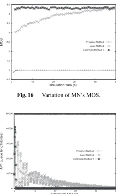
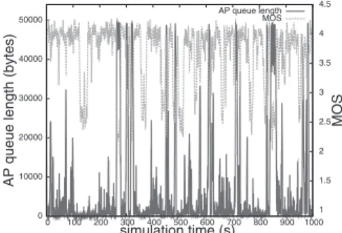
(8) IEICE TRANS. INF. & SYST., VOL.E92–D, NO.10 OCTOBER 2009. 1854. Fig. 16. Fig. 17. Variation of MN’s MOS.. Fig. 18. Variation of MN’s MOS.. Variation of AP1 queue length. Fig. 19. CN through AP1. Figures 16 and 17 show variation of MN’s MOS and AP1 queue length, respectively. As can be seen from Fig. 17, the previous method cannot detect the congestion of AP1 and it continues to utilize the AP1 without executing HO to AP2, hence, AP queue length keeps high as well as adequate VoIP quality cannot be maintained during simulation time. Moreover, the basic method causes a significant fluctuation of AP queue length at initial duration due to simultaneous HOs of all MNs. The basic method can get adequate VoIP quality after gradually decreasing AP queue length. On the other hand, our extension method 1 can maintain VoIP call quality throughout the simulation time because MNs with extension method 1 execute HO in order of the transmission rate. Hence, extension method 1 can avoid the degradation due to the ping-pong effect. 5.3 Evaluation of Extension Method 2 We evaluate the effectiveness for the reduction of the redundant probe packets in extension method 2. We employ two simulation scenarios in Fig. 13 (b). In the first scenario, 42 MNs are randomly located within the overlap area. On the other hand, the second scenario has 48 MNs located randomly within the overlap area. Then, at first, all MNs establish VoIP calls with their CNs through AP1. Figures 18 and 19 show variation of MN’s MOS and AP1 queue length, respectively. From Fig. 18, we can see that, in the extension method 2, although the MOSs in both cases, 42 and 48 MNs, are degrading at the beginning of the simulation, the MOSs are recovered soon. On the other hand, in extension method 1, although the MOS of 42 MNs. Variation of AP1 queue length.. is recovered at one point, after that the MOS is gradually degraded again. In the 48 MNs, the MOS can not be maintained at all. From Fig. 19, we can see that in AP1 queue length, although both results of extension method 1 maintain higher queue length, that of extension method 2 gradually degrades. That is, in the extension method 2, as only one representative MN sends probe packets, the reduction of redundant probe packets brings an increase of acceptable VoIP calls. Therefore, extension method 2 can promptly and reliably execute HO considering the congestion of an AP, while avoiding the ping-pong effect and reducing redundant probe packets. 5.4. Random Movement Environment. Finally, we evaluate the performance of extension method 2 and our previous method in a random movement environment. As shown in Fig. 13 (c), the 15 MNs randomly move between two AP coverage areas at a speed of 1 m/s. Figures 20 and 21 show the MOS and AP1 queue length for the previous method and extension method 2, respectively. From Fig. 20, the average of AP queue length of the previous method is extremely high and the MOS of MNs does not satisfy adequate VoIP quality at all. On the other hand, in Fig. 21, extension method 2 can almost maintain adequate VoIP quality. Also, though some degradation points exists, the MOS can be recovered very quickly. Therefore, MNs can promptly and reliably execute HO considering congestion of an AP by estimating the AP queue length using probe packets..
(9) NISWAR et al.: HANDOVER MANAGEMENT FOR VOWLAN BASED ON ESTIMATION OF AP QUEUE LENGTH AND FRAME RETRIES. 1855. References. Fig. 20. Fig. 21. 6.. Variation of AP1 queue length of our previous method.. Variation of AP1 queue length of the extension method 2.. Conclusion. In a WLAN based on IEEE 802.11 specifications, MNs cannot detect the congestion of an AP. The congestion also contributes the degradation of VoIP quality during movement. In this paper, we thus proposed an HO strategy considering the congestion of an AP. Our proposed method employed probe packets to estimate an AP queue length from RTT between an MN and an AP. However, our proposed method leads to the degradation of VoIP quality due to (1) the ping-pong effect and (2) increase of redundant probe packets. To improve the degradation, we extended the basic method by adding two extension methods. In the first extension, to avoid the simultaneous HOs by many MNs (pingpong effect), we provide a function to execute HO based on the transmission rate. In the second extension, only one representative MN sends probe packets and the other MNs estimate the AP queue length by capturing the probe packets. To show the effectiveness of the proposed methods, we evaluated them through simulation experiments. From the results, compared with the previous method, we showed the proposed methods can promptly and reliable execute HO considering the congestion of an AP while avoiding the ping-pong effect and reducing redundant probe packets. Acknowledgements This work was supported by the Kinki Mobile Radio Center Inc., the Telecommunications Advancement Foundation, and the Japan Society for the Promotion of Science, Grantin-Aid for Young Scientists (B).. [1] C. Perkins, ed., “IP mobility support for IPv4,” IETF RFC3344, Aug. 2002. [2] A. Mishra, M.H. Shin, and W. Arbaugh, “An empirical analysis of the IEEE802.11 MAC layer handoff process,” ACM SIGCOMM Computer Communication Review, vol.33, no.2, pp.93–102, April 2003. [3] R. Koodli, “Fast handovers for mobile IPv6,” IETF RFC4068, July 2005. [4] H. Soliman, C. Castelluccia, K. El Malki, and I. Bellier, “Hierarchical mobile IPv6 mobility management (HMIPv6),” IETF RFC4140, Aug. 2005. [5] S.J. Koh, M.J. Lee, and M. Reigel, “Mobile SCTP for transport layer mobility,” draft-reigel-sjkoh-sctp-mobility-05.txt, Internet draft, IETF, July 2005. [6] J. Fitzpatrick, S. Murphy, and J. Murphy, “An approach to transport layer handover of VoIP over WLAN,” Proc. IEEE CCNC, Jan. 2006. [7] ITU-T: “G.107,” http://www.itu.int/rec/T-REC-G.107/en [8] K. Tsukamoto, T. Yamaguchi, S. Kashihara, and Y. Oie, “Experimental evaluation of decision criteria for WLAN handover: Signal strength and frame retransmission,” IEICE Trans. Commun., vol.E90-B, no.12, pp.3579–3590, Dec. 2007. [9] H. Velayos and G. Karlsson, “Techniques to reduce the IEEE802.11b handoff time,” Proc. IEEE ICC, vol.7, pp.3844–3848, June 2004. [10] S. Kashihara and Y. Oie, “Handover management based on the number of data frame retransmissions for VoWLAN,” Elsevier Computer Communications, vol.30, no.17, pp.3257–3269, Nov. 2007. [11] S. Kashihara, K. Tsukamoto, and Y. Oie, “Service-oriented mobility management architecture for seamless handover in ubiquitous networks,” IEEE Wireless Communications, vol.14, no.2, pp.28–34, April 2007. [12] Y. Taenaka, S. Kashihara, K. Tsukamoto, Y. Kadobayashi, and Y. Oie, “Design and Implementation of cross-layer architecture for seamless VoIP handover,” Proc. IEEE MHWMN, Oct. 2007. [13] Y. Fukuda and Y. Oie, “Decentralized access point selection architecture for wireless LANs —Deployability and robustness,” Proc. IEEE VTC2004-Fall, Sept. 2004. [14] Scalable Network Technologies, http://www.scalable-networks.com/. Muhammad Niswar received the B.E degeree in electrical engineering and M.InfoTech in computer engineering from University of Hasanuddin, Indonesia and University of Newcastle, Australia, respectively. He is currently a Ph.D student in the the Graduate School of Information Science, NAIST, Japan. His research interests include mobile and wireless network..
(10) IEICE TRANS. INF. & SYST., VOL.E92–D, NO.10 OCTOBER 2009. 1856. Shigeru Kashihara received the D.E. degree in information science from Nara Institute of Science and Technology (NAIST), Japan, in 2003. From January 2004 to February 2005 he was a postdoctoral researcher at KIT. He is currently an assistant professor in the Graduate School of Information Science, NAIST. His research interests include mobile and wireless networks. He is a member of the ACM and the IEEE.. Kazuya Tsukamoto received his D.E. degree in computer science from Kyushu Institute of Technology (KIT), Japan, in 2006. From April 2006 to March 2007, he was a Japan Society for the Promotion of Science (JSPS) Research Fellow at KIT. Beginning in July 2006 and ending in January 2007, he spent six months at the Department of Information and Computer Science, University of California, Irvine, on leave of absence from KIT. As of April 2007, he is an assistant professor with the Department of Computer Science and Electronics, KIT. His research interests include performance evaluation of computer networks and wireless networks. He is a member of the IEEE.. Youki Kadobayashi received his Ph.D. degree in computer science from Osaka University in 1997. He is currently an associate professor in the Graduate School of Information Science, Nara Institute of Science and Technology, Japan. His research interests include overlay networks, quality of services in the applicationlayer, and middleware security.. Suguru Yamaguchi was born in Shizuoka, Japan in 1964. He received the M.E. and D.E. degrees in computer science from Osaka Unviersity, Osaka, Japan, in 1988 and 1991, respectively. From 1990 to 1992 he was an Assistant Professor in Education Center for Information Processing, Osaka University. From 1992 to 1993, he was with Information Technology Center, Nara Institute of Science and Technology, Nara, Japan, as an Associate Professor. From 1993 to 2000, he was with Graduate School of Information Science, Nara Institute of Science nad Technology, Nara, Japan, as an Associate Professor. Currently, he is a Professor with the Graduate School of Information Science, Nara Institute of Science and Technology, Nara, Japan. He has been also a member of WIDE Project, since its creation in 1988, where he has been conducting research on network security system for wide area distirbuted computing environment. Since 2004, he was also appoinded to Advisor on information security to the cabinet of Government of Japan. His research interests include technologies for information sharing, multimedia communication over high speed communication channels, network security and network management for the Internet..
(11)
図
+4

関連したドキュメント
In 2003, Agiza and Elsadany 7 studied the duopoly game model based on heterogeneous expectations, that is, one player applied naive expectation rule and the other used
We develop the anholonomic geometry of a Randers space using Holland’s frame and determine two Finsler connections, one of them the crystallographic connection, the other just
Our approach is based on special growth lemmas, and it works for both divergence and nondivergence, elliptic and parabolic equations, in domains satisfying a general “exterior
The study of nonlinear elliptic equations involving quasilinear homogeneous type operators is based on the theory of Sobolev spaces W m,p (Ω) in order to find weak solu- tions.. In
In this paper we develop and analyze new local convex ap- proximation methods with explicit solutions of non-linear problems for unconstrained op- timization for large-scale systems
So far as we know, there were no results on random attractors for stochastic p-Laplacian equation with multiplicative noise on unbounded domains.. The second aim of this paper is
Our main theorem suggests a sharp distinction between λla and the polytime functional systems based on safe recursion [13, 11, 7], because normalization in the latter systems is at
A new numerical method based on Bernstein polynomials expansion is proposed for solving one- dimensional elliptic interface problems.. Both Galerkin formulation and
