Evaluation of image processing algorithms on vehicle safety system based on free-viewpoint image rendering
6
0
0
全文
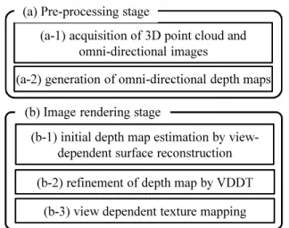
(2) Fig. 1. Example of generated images for virtual camera path that simulates lane change. These images were generated by data captured from the vehicle running on the left lane.. generated based on CG models. Although the use of a virtual environment or a virtualized real environment is expected to drastically reduce the time and cost for developing image processing algorithms for vehicle safety systems, existing techniques for generating images do not reach a sufficient quality of images for evaluation. B. Virtualization of real world by surface reconstruction One alternative to the CG-based systems is to use a virtualized 3D world based on real world data. With the development of 3D scanning systems for outdoor environments, e.g., Topcon IP-S2 [6] and Velodyne HDL-64E [7], it becomes much easier to acquire a 3D point cloud and textures for large outdoor environments. In order to generate textured 3D models of road environments, 3D surfaces should be first generated from the 3D point cloud. Schnabel et al. [8] proposed a method that fits 3D primitives to the 3D point cloud. It successfully works when the geometry of a target 3D point cloud is sufficiently simple to be approximated by the primitives. Yang et al. [9] proposed a method called surface splatting that allocates a local plane for each point to reconstruct 3D surfaces. In order to generate smoother surfaces than a combination of planes or primitives, Liang et al. [5] proposed a surface reconstruction method that estimates surfaces as the boundaries of interior and exterior regions in a 3D point cloud. Although this surface reconstruction technique can fill small gaps in the 3D point cloud by finding local minima of an energy function that is based on the mixture of Gaussian, the problem of the artifacts called fattened-silhouettes, where an object looks fatter than the actual geometry, often appears in generated 3D surfaces. In this paper, we reduce the fattenedsilhouettes using a view-dependent depth test technique with multiple depth maps estimated from images. One remaining problem of surface reconstruction is missing surfaces for the region where no 3D point data is acquired. These unrecovered surfaces will be a severe problem in evaluation of an image-based vehicle safety system because the objects that should exist will disappear from the image. In this paper, we call such artifacts cut-silhouettes and we tackle with this problem by using a free-viewpoint image rendering technique with view-dependent geometry and view-dependent texture mapping. C. Free-viewpoint image rendering Free-viewpoint image rendering is a technique that generates an image whose viewpoint is freely determined. Modelbased rendering (MBR) directly renders the image from. a virtual viewpoint using view-independent 3D geometry (3D model) and view-independent (fixed) textures. Although reconstructed 3D surfaces by the methods introduced in the previous section can be rendered by MBR, errors of the reconstructed 3D model appear as distortion in the rendered textures in this simple renderer. In order to reduce such distortion, view-dependent texture is known as an effective solution [10]. In addition to the use of view-dependent texture mapping, a view-dependent geometry generation technique [11] is also proposed to remove the problem of the missing surfaces in generated images. In this paper, although we employ the combination of view-dependent texture mapping and view-dependent geometry, we extend the existing freeviewpoint image rendering techniques for reducing fattened/cut-silhouettes in order to generate photo-realistic images for evaluation of vehicle safety systems. III. Free-viewpoint Image Rendering from 3D Point Cloud and Images A. Overview Figure 2 shows the pipeline of free-viewpoint image rendering in the proposed framework. The pipeline is consists of two stages: (a) the pre-processing stage and (b) the image rendering stage. In the pre-processing stage, a 3D point cloud and omni-directional images of a road environment are acquired using a scanning vehicle such as IP-S2 [6]. From these data, an omni-directional dense depth map is generated for each frame of the omni-directional image considering both the 3D point cloud and the image data. In the rendering stage (b), after setting a virtual camera position, we estimate a view-dependent depth map for the virtual camera position. The estimated depth map is then refined to reduce fattened/cut-silhouettes using view-dependent depth test (VDDT) with multiple dense depth maps prepared in the stage (a). Using the refined depth map for the virtual camera position, a free-viewpoint image is rendered using a view-dependent texture mapping technique. Each stage in our pipeline is described in the following sections. B. Pre-processing stage (a-1) Acquisition of 3D point cloud and omni-directional images In the proposed framework, a 3D point could and omnidirectional images that are taken along a road are required with the accurate positions of a scanning vehicle. In order to collect these data, we employed Topcon IP-S2 [6]. In this system, three SICK LiDARs, Point Grey Ladybug 3, Topcon.
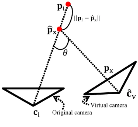
(3) (a) Pre-processing stage (a-1) acquisition of 3D point cloud and omni-directional images (a-2) generation of omni-directional depth maps. (a) original image. (b) re-projected 3D point cloud. (b) Image rendering stage (b-1) initial depth map estimation by viewdependent surface reconstruction (c) segmented image. (b-2) refinement of depth map by VDDT (b-3) view dependent texture mapping Fig. 2.. Fig. 3.. (d) dense omni-directional depth map. Dense depth map estimation using both 3D point cloud and image. A pixel colored in pink indicates an infinity depth value.. Pipeline of proposed free-viewpoint image rendering framework.. fattened-silhouette. RTK-GPS, and an odometry sensor are mounted on a vehicle, and the 3D point cloud of a surrounding environment with absolute position and omni-directional images can be easily collected by driving the vehicle. (a-2) Generation of omni-directional depth maps In order to remove fattened-/cut-silhouettes in generated images, we estimate an omni-directional dense depth map for each omni-directional image using both the 3D point cloud and the omni-directional image (Figure 3). Here, for each viewpoint, we first select the visible 3D points out of the 3D point cloud by comparing the distances from the viewpoint to the 3D point and estimate the surface by using the surface reconstruction technique by Liang et al. [5]. After removing the hidden points that exist on the far side of the reconstructed surface, sparse depth data generated by projecting selected 3D points (Fig. 3 (b)) are converted to a dense depth map (Figure 3 (d)) using the image data. For compensating infinite depth region including the sky region, we first divide the omni-directional image into the sky region and the ground region based on the intensity of the pixels. After that, as shown in Figure 3 (c), the ground region of the omni-directional image is segmented by the watershed segmentation algorithm [12] using the projected point as a seed of each segment, and the depth value for every pixel is filled based on the segments with the depth of the seed. C. Image rendering stage (b-1) Initial depth map estimation by view-dependent surface reconstruction In the image rendering stage, we first estimate an initial depth map by applying Liang’s surface reconstruction technique [5] with a view-dependent manner. More concretely, for each pixel on an image of a virtual camera, 3D points that exist around the ray from a viewpoint cˆ v of the virtual camera to the direction of the pixel on the image plane are selected first. Using selected 3D points, the closest depth, for which the score function defined in the paper [5] gives a local maximum, is selected. Figure 4 shows an example of the estimated initial depth map and the generated image. As shown in this figure, generated image with the initial depth. cut-silhouette (a) depth map Fig. 4.. (b) free-viewpoint image. Depth map and free-viewpoint image with fattened/cut-silhouette.. map has fattened-/cut-silhouettes. (b-2) Refinement of depth map by VDDT In order to reduce the fattened-/cut-silhouettes, we employ view-dependent depth test (VDDT). The idea is inspired by Yang’s method [9], but we extend the test scheme to handle both two problems with a noisy input. VDDT consists of fattened-silhouette removal and cut-silhouette compensation as follows. (i) Fattened-silhouette removal: Fattened-silhouette is detected for each pixel by checking the consistency of the depths prepared in the pre-processing stage. As shown in Figure 5, 3D position pˆ x for target pixel p x is recovered using the initial depth. This 3D position pˆ x is then projected onto the original images of the top N-nearest camera positions ci (i = 1 . . . N) and 3D position pi which is recovered using the projection result for pˆ x to ci is acquired. Using these recovered 3D points, the consistency of estimated depths for the 3D position p x is evaluated as the sum of weighted errors as follows: ∑ wi ||pi − pˆ x || Err(p x ) = i ∑ , i wi (1) 1 θ+λ||pˆ x −ci || ; ||pˆ x − ci || ≤ ||pi − ci || wi = , 0 ; otherwise where θ in [0, π] is defined by θ = ∠ˆcv pˆ x ci as in Figure 5 and λ is a pre-defined parameter. Using this error function, an initial depth that is inconsistent with the depths on original images is detected. For the pixels for which Err exceeds a.
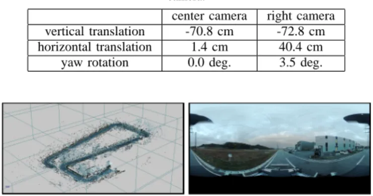
(4) 3000> 2500 2000 1500 1000 500 0. map (a) considering fattened-silhouette. Fig. 6.. (b) depth map without fattened-silhouette. Fattened-silhouette removal result.. Virtual camera Original camera 3000> 2500. Fig. 5.. Parameters in VDDT. 2000. given threshold, we find another depth value that greater than ||pˆ x − cˆ v || using the method [5]. Figure 6 shows an example of function Err and a depth map after refinement. From this figure, we can see that fattened-silhouettes of objects are successfully removed. (ii) Cut-silhouette compensation: After removing fattenedsilhouettes, missing surfaces in the estimated depth map are compensated. For detection of cut-silhouettes, we use the same function Err defined in Eq. (1) with different weight wˆ i : 1 θ+λ||pˆ x −ci || ; ||pˆ x − ci || > ||pi − ci || wˆ i = . (2) 0 ; otherwise We judge the pixels, where Err with weight wˆ i exceeds a given threshold, as cut-silhouettes and for these pixels, we find an alternative depth value using the image-based freeviewpoint rendering technique proposed by Sato et al. [11]. Figure 7 shows an example of the function Err with wˆ i and a compensated depth map where cut-silhouettes of objects are compensated. (b-3) View-dependent texture mapping For each pixel in the image for a virtual camera, its color is determined from omni-directional images which are acquired in the pre-processing stage (a-1). Here we employ the viewdependent texture mapping technique by Sato et al. [11] to determine the pixel color. IV. Experiments In this section, we verify the applicability of the proposed framework for evaluation of image processing algorithms on vehicle safety systems. For this purpose, we have compared the outputs of the white line detection algorithm [13] for real images and virtual images generated by the proposed framework. Figure 8 shows a 3D point cloud and an example frame of the omni-directional image sequence for the road and the surroundings acquired by Topcon IP-S2 [6] for this experiment. While capturing these data, real images for the comparison were also taken by two real camera units (Point Grey Research: Flea3) mounted on the vehicle at the positions shown in Figure 9. Table 1 shows parameters of the real cameras used in this experiment.. 1500 1000 500 0. map (a) considering cut-silhouette. Fig. 7.. (b) depth map with compensated region of cut-silhouette. Result for compensating region of cut-silhouette.. From acquired data, we have generated two image sequences (31 frames for each sequence) for two virtual cameras that simulate a 60 m drive with the speed of 36 km/h. The camera parameters and camera paths of two virtual cameras were manually set to be the same as those of the external cameras. Table 2 shows the translation and rotation of the virtual cameras from the omni-directional camera. As shown in Figure 10 (a), a generated virtual image had some differences from a corresponding real image in the tone of color and the bottom part of the image where the vehicle was framed-in in the real image, and disappeared in the generated image. For reducing undesired effects due to these differences, we manually adjusted the tone of color of generated images and cropped the bottom parts (8% for the center camera and 10% for the right camera) of both real and generated images (Figure 10 (b)). Figure 11 shows comparison between real images and virtual images generated by the proposed framework. As we can see in this figure, very similar images to the real images were successfully generated except for tiny artifacts. Figure 12 shows white lines detected by the existing method [13] in the images shown in Figure 11. Offset positions of white lines detected from the center and the right camera positions are shown in Figure 13. For the center camera, the average absolute differences between pairs of offset positions for the real and virtual cameras were 37 mm and 24 mm for the right and left white lines, respectively. For the right camera, they were 35 mm and 25 mm. The difference is reasonable considering the stability and the accuracy of the white line detection algorithm. This evaluation was done for a very short video sequence as the first step of the development. We recognize the neces-.
(5) Table 1. Specifications of the camera units.. resolution field of view. 640 × 512 px. 67 × 56 deg.. Table 2. Translation and rotation of virtual cameras from omni-directional camera.. vertical translation horizontal translation yaw rotation. center camera -70.8 cm 1.4 cm 0.0 deg.. right camera -72.8 cm 40.4 cm 3.5 deg.. (a) original real image (left) and generated image (right). (b) edited real image (left) and generated image (right) Fig. 10.. Adjustment of a tone of color and cropping of bottom part of images.. Fig. 8. Acquired 3D point cloud (left) and omni-directional image (right).. omni-directional camera. Acknowledgement. external right camera external center camera Fig. 9.. Positions of the camera units.. sity for doing a large scale evaluation with various algorithms using the proposed framework. One remaining problem of such a large scale evaluation is computational cost for generating images. Currently, using Intel(R) Core(TM) i73970X (and nVidia GTX680 in the processes (a-2), (b1)), generating one omni-directional depth map in the preprocessing stage took 58 minutes and generating one freeviewpoint image in the rendering stage took 72 minutes, on average. V. Conclusion In this paper, we have proposed a free-viewpoint image rendering technique and outputs of the white line detection algorithm have been compared using real images and virtual images generated by the proposed framework. From the results, the errors of detected positions of white lines were very small. This indicates the applicability of our freeviewpoint image rendering framework as an alternative to the real images to evaluate image processing algorithms on vehicle safety systems. In the future, we will improve the efficiency of the proposed framework and its implementation, and we will conduct a large scale evaluation with various image processing algorithms on vehicle safety systems and various driving situations.. This research was supported in part by Toyota Central R&D Lab., Inc., the Japan Society for the Promotion of Science (JSPS) Grants-in-Aid for Scientific Research, Nos. 23240024 and 25540086. References [1] TASS prescan https://www.tassinternational.com/prescan-overview [2] G. Weinberg, and B. Harsham, “Developing a Low-Cost Driving Simulator for the Evaluation of In-Vehicle Technologies,” Proc. Int. Conf. Automotive User Interfaces and Interactive Vehicular Applications, pp.51-54, 2009. [3] R. Sato, S. Ono, H. Kawasaki, and K. Ikeuchi, “Real-time Image Based Rendering Technique and Efficient Data Compression Method for Virtual City Modeling,” Proc. Meeting on Image Recognition and Understanding, IS-3-28, pp.1087-1092, 2007. (in Japanese) [4] H. Yasuda, N. Yamada and E. Teramoto, “An Evaluation Measure of Virtual Camera Images for Developing Pedestrian Detection Systems,” Proc. 2011 IEICE General Conference, D-11-80, p.80, 2011. (in Japanese) [5] J. Liang, F. Park, and H. Zhao, “Robust and Efficient Implicit Surface Reconstruction for Point Clouds Based on Convexified Image Segmentation,” Journal of Scientific Computing, Vol.54, No.2-3, pp.577-602, 2013. [6] IP-S2 http://www.topcon.co.jp/en/positioning/products/product/3dscan ner/ip s2.html [7] HDL-64E http://velodynelidar.com/lidar/hdlproducts/hdl64e.aspx [8] R. Schnabel, P. Degener, and K. Reinhard, “Completion and Reconstruction with Primitive Shapes,” Proc. Eurographics, Vol.28, No.2, pp.503-512, 2009. [9] R. Yang, D. Guinnip, and L. Wang, “View-dependent Textured Splatting,” The Visual Computer, Vol.22, No.7, pp.456-467, 2006. [10] P. Debevec, Y. Yu, and G. Borshkov, “Efficient View-dependent Imagebased Rendering with Projective Texture-mapping,” Proc. Eurographics Rendering Workshop, pp.105-116, 1998. [11] T. Sato, H. Koshizawa, and N. Yokoya, “Omnidirectional Freeviewpoint Rendering Using a Deformable 3-D Mesh Model,” Int. Journal of Virtual Reality, Vol.9, No.1, pp.37-44, 2010. [12] S. Beucher, and F. Meyer, “The Morphological Approach to Segmentation: The Watershed Transformation,” Mathematical Morphology in Image Processing, Marcel Dekker Press, pp.433-481, 1992. [13] A. Watanabe, and M. Nishida, “Lane Detection for a Steering Assistance System,” Proc. IEEE Intelligent Vehicles Symp., pp.159-164, 2005..
(6) frame #1. frame #1. frame #11 (b) right camera. frame #11 (a) center camera Fig. 11.. Comparison of real images (left column) and virtual images (right column) for corresponding positions.. frame #1. frame #1. frame #11 (b) right camera. frame #11 (a) center camera Fig. 12.. Result of white line detection for real images (right column) and virtual images (left column).. 31. 31. 25. 25. frame number. frame number. 20 15 10 5. 20 15 10 5. 1. 1. -1.5. -1.0. -0.5. 0.0 0.5 1.0 offset distance. 1.5. 2.0 [m]. -2.0. -1.5. -1.0 -0.5 0.0 0.5 offset distance. 1.0. 1.5. distance to left white line from center real images. distance to right white line from center real images. distance to left white line from right real images. distance to right white line from right real images. distance to left white line from center virtual images. distance to right white line from center virtual images. distance to left white line from right virtual images. distance to right white line from right virtual images. (a) center camera Fig. 13.. (b) right camera. Offset positions of detected white lines for real and virtual images.. [m].
(7)
図

+2

関連したドキュメント
In this paper, we propose the column-parallel LoS detection architecture for the integrated image sensor, which has a capability to track the saccade, as well as its implementation
Abstract The purpose of our study was to investigate the validity of a spatial resolution measuring method that uses a combination of a bar-pattern phantom and an image-
In the present paper, the criterial images for GIF- compression attack are selected by the proposed criterial image preparation method, and the obtained criterial images are added
We compared CT image qualities of iNoir with FBP and ASIR using phantom tests corresponding to pediatric abdominal CT and a human observer test using clinical images..
Nevertheless, as demonstrated by our evaluation, quasicrystal sampling is shown to be proficient at supporting a uniform sampling density, centroidal Voronoi regions, accurate
The denoising results for pixels near singularities are obtained by nonlocal means in spatial domain to preserve singularities while the denoising results for pixels in smooth
A class of nonlinear fourth-order telegraph-di ff usion equations TDE for image restoration are proposed based on fourth-order TDE and bilateral filtering.. The proposed model
At the same time, a new multiplicative noise removal algorithm based on fourth-order PDE model is proposed for the restoration of noisy image.. To apply the proposed model for
