Title
インパルスモデルに基づくパワー半導体デバイスの損失計算手法
Author(s)
白濱 秀文
Citation
福岡工業大学エレクトロニクス研究所所報 第34巻 P41-P43
Issue Date
2017-10
URI
http://hdl.handle.net/11478/778
Right
Type
Departmental Bulletin Paper
Textversion publisher
福岡工業大学 機関リポジトリ
FITREPO
福岡工業大学研究所所報(2017)
インパルスモデルに基づくパワー半導体デバイスの損失計算手法
白濱 秀文(工学部電気工学科)
武藤
司
(工学部電気工学科)
Power Loss Calculation Method based on Impulse Model for Power Semiconductor Devices
Hidefumi SHIRAHAMA (Department of Electrical Engineering, Faculty of Engineering) Tsukasa MUTOU (Department of Electrical Engineering, Faculty of Engineering)
Abstract: When designing a power electronics equipment such as rectifiers and inverters, it is indispensable to calculate power loss of power semiconductors for estimation of power conversion efficiency, which influences mounting and cooling design of the equipment. In this paper, new approach for power loss calculation of power semiconductors based on Impulse Model is proposed. Proposed method is achieved by MATLAB-Simulink, and then the precision of the method is compared with that of a conventional loss calculation way. As a result, it is proved that the proposed method is practical.
Keywords: Power loss calculation, Impulse model, Power semiconductor
1. はじめに 整流器,インバータなどのパワーエレクトロニクス応用 機器を設計する場合,実装・冷却方式を左右する電力変換 効率の把握は重要であり,その基礎となるのがパワー半導 体デバイスの損失計算である。一般に,回路構成に応じた 近似的な計算式により損失計算を行なっているが,回路変 更が生じると,新たに計算式を導出することになるので, 汎用性がない。また,シミュレーションで損失を求める場 合,半導体デバイスの詳細な動特性モデルが必要となる。 本論文では,データシートなどで公開されているデバイ ス特性データに基づきスイッチング損失をインパルス波形 化することにより,デバイスの過渡特性に立ち入ることな く電力損失をシミュレーションで求める手法を提案する。 また,提案手法を MATLAB-Simulink で実現し,従来の損失 計算式による結果と比較し,その有用性を検証する。 2. 損失計算手法 〈2・1〉 概略構成 図1に,提案手法をブロック図で示す。図は,IGBT モジ ュールを対象とした一例であり,損失関数,サンプラ,サ ンプラ操作信号作成系,および加算器から成っており,加 算器の出力波形をフーリエ解析することにより損失を計算 することができる。損失関数は,スイッチング損失関数と 導通損失関数を含み,スイッチング損失関数は,IGBT モジ ュールのターンオン損失,ターンオフ損失,およびリカバ リー損失を算出する関数である。また,導通損失関数は, IGBT および還流ダイオードの導通損失を算出する。サンプ ラは,IGBT モジュールのコレクタ電流とコレクタ・エミッ タ間電圧の瞬時値に対応したスイッチング損失関数の出力 をインパルス波形化し,インパルス波形と導通損失関数の 出力を加算器で合成し,フーリエ解析のための損失波形を 得る。 図1 提案手法のブロック図 Fig.1 Block diagram of proposed method
図2 損失波形に含まれる成分
Fig.2 Components included in power loss waveform
𝒗𝒈 𝒊𝒄 𝒗𝒄𝒆 𝑷 𝒍𝒐𝒔𝒔 スイッチング 損失関数 導通損失関数 サンプラ操作 信号作成系 + フーリエ解析 デバイスモジュール 𝑷𝒔𝒘 𝑷𝒄𝒐𝒏 𝑷𝒔𝒘∗ 𝑻 損失関数 (サンプラ) ターンオン損失波形 ターンオフ損失波形 IGBT導通損失波形 リカバリー損失波形 ダイオード導通損失波形 スイッチング 損失波形 IGBTモジュールの 損失波形 導通損失波形
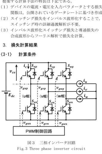
白濱 秀文,武藤 司 フーリエ解析の対象であるIGBT モジュールの損失波形 は,図2に示すように,インパルス波形化されたスイッチ ング損失波形と導通損失波形を合成したものであり,スイ ッチング損失波形には,モジュール内IGBT のターンオン およびターンオフ損失をインパルス波形化した成分と還流 ダイオードのリカバリー損失成分をインパルス波形化した 成分を含んでいる。また,導通損失波形は,IGBT および還 流ダイオードの導通損失波形の合成である。 〈2・2〉 提案手法の特長 提案する計算手法の特長は下記である。 (1)デバイスの電流・電圧を入力パラメータとする損失 関数は,公開されているデータシートに基づき作成。 (2)スイッチング損失をインパルス波形化することで, スイッチング時の詳細過渡解析が不要。 (3)インパルス波形化スイッチング損失と導通損失の 合成波形からフーリエ解析で損失を計算。 3. 損失計算結果 〈3・1〉 計算条件 図3 三相インバータ回路 Fig.3 Three phase inverter circuit
表1 計算条件
Table 1. Conditions of loss calculation
MATLAB-Simulink によるシミュレーションで,提案手法の 有用性を評価した。シミュレーション回路は図3に示す基 本的な三相インバータとし,データシートは,IGBT モジュ ール MBN1200E25C の公開資料を利用した。また,運転条件 は表1とした。 〈3・2〉 計算結果 上記計算条件に従い,シミュレーションを実施した。図 4に損失波形例を示す。図は,図3のインバータ回路にお けるU 相上アームの IGBT モジュールに関する損失波形で あり,図中の波形(1)(2)は,IGBT モジュールのコレ クタ・エミッタ間電圧,およびコレクタ電流である。また, (3),(4),(5)および(6)は,それぞれIGBT ター ンオン・ターンオフ損失波形,還流ダイオードのリカバリ ー損失波形,IGBT の導通損失,および還流ダイオードの導 通損失波形を示している。これらの損失波形をフーリエ解 析することにより各損失成分の値が求まる。
𝒗
𝒄 𝒆V
𝒊
𝒄A
𝑷
𝒔V
A
𝑷
𝒓V
A
𝑷
𝒄 𝒊V
A
𝑷
𝒄 𝒅V
A
s
1
2
3
5
6
4
図4 電力損失のシミュレーション波形 Fig.4 Simulation waveforms of power lossPWM制御回路 𝑬𝒅𝒄 𝒊𝒖 𝒊𝒗 𝒊𝒘 𝒊𝒄 𝒗𝒄𝒆 (U相) (V相) (W相) 𝒗𝒈𝒖𝒑 𝒗𝒈𝒗𝒑 𝒗𝒈𝒘𝒑 𝒗𝒈𝒖𝒏 𝒗𝒈𝒗𝒏 𝒗𝒈𝒘𝒏 𝑺𝒖𝒑 𝑺𝒗𝒑 𝑺𝒘𝒑 𝑺𝒖𝒏 𝑺𝒗𝒏 𝑺𝒘𝒏 項 目 記 号 条 件 直流電源電圧 𝑬𝒅𝒄 1.0 [kV] インバータ出力電流 𝒊𝒖,𝒗,𝒘 353 [Arms] (ピーク:500 A) スイッチング周波数 𝒇𝒔𝒘 1.0 [kHz] 出力周波数 𝒇𝒐 50 [Hz] 変調率 𝑲 0.8 力率 𝐜𝐨𝐬 𝝓 0.9
インパルスモデルに基づくパワー半導体デバイスの損失計算手法 〈3・3〉 従来計算式との比較 表1は従来の近似的な計算との比較である。開発した手 法は,従来の方法に対して IGBT モジュール損失(総合損 失)で0.2%程度の差があるが,実用上,十分な精度が得ら れていると考える。 表2 計算結果 Table 2. Calculation results
4. まとめ 公開データのみでデバイスの損失を計算できる汎用計算 手法を開発し,シミュレーションにより,その有用性を確 認した。今後は,実験による検証を行い,熱モデルとの連 成解析につなげていく予定である。 (平成29年7月20日受付) 文 献 (1) IGBTモジュールの損失・温度シミュレータ、富士時報 Vol.81 No.6 2008 項 目 従来損失 計算式 [W] 提案計算 手法 [W] IGBTターンオン損失 209.0 204.1 IGBTターンオフ損失 253.5 259.5 FWDリカバリー損失 120.8 117.7 IGBT導通損失 215.7 216.0 FWD導通損失 42.5 42.5 IGBT部損失 678.2 679.6 FWD部損失 163.3 160.2 IGBTモジュール損失 841.5 839.8